

Categories
Design, Cost & Sourcing

Master CAD for CNC: 5 Essential Prep Steps for Perfect Cuts

Getting your CAD model ready for CNC machining is a crucial step that bridges design and physical part. This guide walks you through five essential preparation steps to ensure your digital designs translate into flawless, machined components, saving you time and material.

Embrace Design for Manufacturing (DFM)

Think of preparing a CAD file for CNC like giving a chef a perfect recipe. If the instructions are unclear or the ingredients don’t exist, the final dish won’t turn out right. The first and most important step is to design with manufacturing in mind from the very beginning. This concept, often called Design for Manufacturability (DFM), means creating your 3D model not just for looks, but for how it will actually be made on a CNC milling machine or lathe.

Understanding Tool Access and Geometry

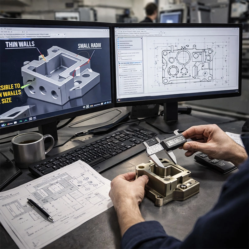
You need to consider the cutting tools. They are cylindrical and have a limited reach. A classic pitfall is designing an internal pocket with sharp, square corners—a standard end mill can’t cut those! You’ll need to either specify a smaller tool (which takes more time) or design filleted corners. Similarly, avoid excessively deep, narrow cavities or features with undercuts that a tool simply cannot physically reach. Asking yourself, “How will a tool get here?” during the CAD modeling for CNC phase saves countless headaches later.

Ensure Model Accuracy and Integrity

Before you even think about exporting, your 3D model needs a thorough health check. A model with tiny gaps, overlapping surfaces, or stray “orphaned” geometry can cause the CAM (Computer-Aided Manufacturing) software to fail or produce incorrect toolpaths. It’s like trying to build a house with warped lumber—the foundation is off. Ensuring a “watertight” or “manifold” solid model is non-negotiable for successful CNC programming from CAD.

Checking for Gaps and Overlaps

Most CAD software has built-in analysis tools to find these issues. Run a check for interferences, zero-thickness geometry, and open edges. Fixing these problems in CAD is almost always easier than trying to decipher cryptic error messages in your CAM system. A clean, robust model is the best starting point for generating reliable G-code, the language that drives your CNC machine.

Set Realistic Tolerances and Finishes

Not every surface of your part needs to be mirror-smooth, and not every dimension needs to be held to a thousandth of an inch. Unnecessarily tight tolerances and fine surface finishes dramatically increase machining time and cost. In your CAD model or accompanying drawing, clearly define critical dimensions and their tolerances. For non-critical features, leave standard machining tolerances. Also, specify surface finish requirements (like a machined finish vs. a polished one) only where needed for function. This clarity is a key part of creating CNC-ready CAD files that are efficient to produce.

Choose the Right CAD File Format

This is where the digital handoff happens. While your native CAD file (like a .SLDPRT or .F3D) is great for editing, the manufacturing world often relies on neutral, universal formats. The most common and reliable format for 3D CAD to CNC conversion is STEP (.step or .stp). It preserves solid body geometry and is widely supported. IGES is an older alternative but can be less reliable with complex surfaces. For simple 2.5D parts, even a DXF of your profiles can work. When in doubt, STEP is usually the safest bet to ensure your design intent is communicated without errors.

Include Technical Drawings & Notes

Even with a perfect 3D model, a 2D drawing is an indispensable communication tool. Think of it as the instruction manual for your part. It should include orthographic views, all critical dimensions with tolerances, key geometric tolerances (like flatness or perpendicularity), surface finish symbols, and material callouts. Also, use notes to specify thread types, deburring requirements, or any post-processing like anodizing. Providing a clear drawing alongside your CAD file is the final, professional touch in the CAD to CAM workflow. It eliminates guesswork for the machinist and is considered a best practice by leading authorities like Engineering.com.
Categories
Design, Cost & Sourcing

Master CNC Machining Design Rules: 7 Essential Tips for Success

Getting your part design right for CNC machining is crucial for success. This guide walks you through seven fundamental design for manufacturability principles to make your parts easier, faster, and more cost-effective to produce. We’ll cover everything from wall thickness to tool access.

Key Design Principles for Effective CNC Machining

Think of CNC machining design rules as a friendly conversation between you and the machine shop. By following these design for manufacturability guidelines, you’re essentially giving clear, easy-to-follow instructions. This leads to fewer headaches, lower costs, and parts that come out exactly as you envisioned. The core idea is to design with the cutting tool in mind—understanding its shape, size, and how it moves can prevent a lot of common issues.

Mind Your Internal Corners and Radii

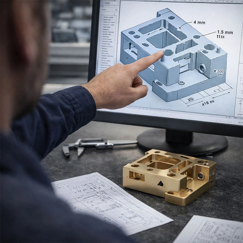
Here’s a simple but powerful tip: avoid sharp internal corners. Cutting tools are round, so they can’t create a perfect 90-degree inside corner. Instead, they leave a rounded fillet. The rule of thumb is to specify an internal radius slightly larger than the tool that will be used. For instance, if you’re using a standard 0.25-inch end mill, design your corners with at least a 0.125-inch radius. This is a fundamental CNC design guideline that prevents tool stress and ensures cleaner cuts.

Why Radii Matter

Specifying proper corner radii allows the tool to follow a smooth path, which improves surface finish and extends tool life. It also avoids the need for expensive, specialized tooling just to reach a sharp corner. When you’re drafting your part, always ask yourself, “Could a round tool make this cut easily?

Maintain Adequate Wall Thickness

Thin walls are a common pitfall in machining part design. During the milling process, tools exert significant force. If a wall is too thin, it can vibrate, warp, or even break, ruining the part. We generally recommend a minimum wall thickness of 1/32 inch (about 0.8 mm) for metals and 1/16 inch (about 1.5 mm) for plastics. Sturdier walls mean a more reliable machining process and a stronger final component.

Design Smartly for Deep Pockets and Cavities

Designing deep pockets or cavities? Remember that longer tools are less rigid and can deflect, causing inaccuracies. A great design for manufacturing tip is to limit the depth of any pocket to four times its width. If you need something deeper, consider designing it as a through-pocket or adding large relief holes in the bottom for the tool to pass through. This makes chip removal much easier and improves the overall machining strategy.

Follow Best Practices for Hole Design

Holes are everywhere in machined parts, and a few simple CNC milling design tips can make them perfect. First, standardize hole sizes to common drill bit diameters to avoid custom tools. Second, for threaded holes, ensure there is enough material around the hole for the threads to hold securely. Lastly, specify a flat bottom for holes that are blind (not going all the way through) to give the drill bit a proper surface to start on. You can find excellent reference charts for standard drill sizes and thread depths on engineering resource sites like Engineers Edge.

Keep Text and Engraving Legible

Adding part numbers or logos? Engraving text with a V-bit is common, but the details matter. Use sans-serif fonts like Arial or Verdana, and keep the font size large enough—typically 20 points or more. Also, make the engraving at least 0.5 mm deep. Shallow engraving can look faint and wear off easily. This attention to detail in your design for CNC machining ensures markings are clear and durable.

Choose the Right Material for the Job

Your material choice is a key part of DFM for CNC machining. Aluminum 6061 is a fantastic all-rounder—easy to machine, strong, and readily available. For higher strength, consider 7075 aluminum or steel. Plastics like Delrin (POM) and Nylon are great for insulators and wear parts. Always consider the part’s function, required tolerances, and budget when selecting. The material directly affects machining time, tool wear, and cost.

The Power of a Final Design Review

Before you send your files off, take a moment for a final review. Look at your model from the perspective of the cutting tool. Can all features be reached? Are there any unnecessary complexities that could be simplified? Running a quick design for manufacturability check often catches small issues that make a big difference. When in doubt, don’t hesitate to consult with your machine shop early in the process—they’re your partners in turning a great design into a perfect part.

Request A Quote

We'll Send You Back with Price Immediately!

DEC 1-31

XMAS SPECEIL

Up to

40% off

Master CNC Machining Design Rules: 7 Essential Tips for Success

We'll Send You Back with Price Immediately!