

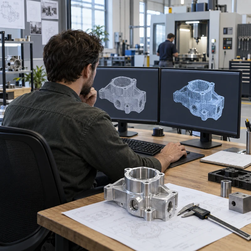
Image-to-3D tools can reconstruct a mesh from one or more photographs in minutes. That speed is useful for visualization and concept exploration, but the output should not be confused with an engineering CAD model. A mesh can look convincing on screen while containing incorrect dimensions, broken surfaces, impossible internal geometry, or topology that fails during slicing and CAM preparation.
Instead of choosing software by render quality alone, manufacturers should evaluate view consistency, mesh validity, scale, editability, export formats, privacy, commercial rights, and the effort required to reach a controlled CAD model.
Quick Answer
Use image-to-3D generation for concept form, reference geometry, and fast visual models. Repair the mesh before printing, and rebuild critical products in parametric CAD before CNC machining, tooling, tolerance analysis, or production release.
Comparison at a Glance
| Criterion | Good result | Manufacturing warning |
|---|---|---|
| Shape reconstruction | Consistent form across all views | Invented back-side or hidden features |
| Topology | Closed manifold mesh with rational density | Holes, self-intersections, floating shells |
| Scale | Known reference dimension | Arbitrary units or distorted proportions |
| Editability | Local repair and controlled export | One-click regeneration changes the whole model |
| Rights and privacy | Clear commercial license and data policy | Restricted use or confidential uploads retained |
What a Single Image Cannot Tell the Model
A photograph does not reveal hidden faces, true depth, wall thickness, internal channels, thread geometry, material, or tolerance. The system estimates those details from learned visual patterns. A plausible estimate may be acceptable for a character or decorative asset, but it is not evidence of mechanical correctness.
Use several controlled views when the tool supports them. Keep focal length, lighting, and orientation consistent, and include a scale reference. Even then, verify all interfaces independently.
Mesh Quality Comes Before Visual Quality
Inspect the exported mesh rather than judging only the preview render. Common failures include non-manifold edges, inverted normals, intersecting surfaces, duplicate shells, holes, thin regions, irregular triangles, and unnecessary polygon counts.
A watertight mesh is necessary for many printing workflows, but watertight does not mean manufacturable. A repaired file can still have weak walls, inaccessible cavities, unrealistic clearances, or geometry that cannot be inspected.
- Run manifold and self-intersection checks
- Remove floating components
- Confirm wall thickness and clearances
- Reduce polygons without destroying edges
- Test the final export, not only the cloud preview
Scale and Dimensional Control
Generated meshes often have no trustworthy units. Establish at least one known dimension, then measure several independent features to detect non-uniform distortion. Scaling the whole object cannot correct a housing whose width, height, and hole pattern were reconstructed at different proportions.
For reverse engineering, measured data from calipers, CMM, structured-light scanning, or drawings should control the final model. Photographs can support shape interpretation but should not replace measurement.
From AI Mesh to 3D Printing
Concept models can often be printed after mesh repair, orientation, hollowing, support design, and minimum-wall checks. Choose the print process based on what the model must prove: inexpensive FDM for size and handling, resin for visual detail, or nylon powder for functional geometry.
Print a reduced-risk test first when the model has thin sections or uncertain surfaces. Record any manual repairs so later regeneration does not silently remove them.
From AI Mesh to CNC-Ready CAD
CNC manufacturing needs explicit planes, cylinders, hole sizes, datums, corner radii, tool access, workholding surfaces, material, tolerances, threads, and finish notes. Triangle meshes do not naturally provide these controls.
Use the mesh as an underlay and rebuild critical geometry with sketches and parametric features. Direct mesh-to-solid conversion may work for simple low-density objects, but dense organic meshes often create heavy files and fragile surfaces that are difficult to revise.
- Rebuild mating interfaces first
- Create machinable internal radii
- Define standard holes and threads
- Add stock and fixture access
- Export STEP and issue a controlled drawing
How to Compare Two Image-to-3D Platforms
Run the same input set through both tools and score the downloadable output. Do not rely on vendor showcase examples. Measure reconstruction consistency, hidden-side behavior, topology, texture quality, processing time, export access, edit controls, credit cost, and licensing.
A tool that produces a slightly less attractive preview but a cleaner, editable mesh may save more engineering time. For manufacturing, downstream repair effort matters more than the first render.
Security, Licensing, and Traceability
Before uploading customer products, drawings, or unreleased designs, review retention, training use, ownership, regional storage, deletion, and commercial licensing terms. Public AI services may not be suitable for controlled technical data.
Keep the source images, prompt, model version, exported mesh, repair history, and final CAD revision together. This creates traceability when the geometry changes or a license question arises.
Manufacturing Acceptance Checklist
The model is ready for quotation only when its purpose and remaining uncertainty are visible to the supplier.
- Units and overall scale confirmed
- Mesh validity checked
- Critical dimensions rebuilt or documented
- Material and process selected
- Tolerances and datums identified
- Threads and inserts specified
- Commercial rights and confidentiality approved
Frequently Asked Questions
Can a single product photo create an accurate 3D model?
It can create an approximate visible form, but hidden geometry and depth are inferred. Accurate mechanical work needs multiple views plus measured dimensions or scan data.
Can an AI-generated mesh go directly to a CNC machine?
CAM may import some meshes, but reliable CNC production normally requires repaired surfaces or rebuilt CAD, defined tolerances, material, setup planning, and drawings.
Which export format is best?
OBJ, STL, or GLB are common for meshes and visualization. STEP is generally preferred for controlled mechanical CAD and CNC quotation after the geometry has been rebuilt.