Categories
Blog Design, Cost & Sourcing

Sheet Metal Bracket Design: Bends, Loads, Holes, and Assembly Fit

Good sheet metal bracket design begins with the load path, mounting interfaces, material condition, and bend process. Hole placement, flange length, internal radius, fastener access, finish, and inspection must work together. A bracket that is easy to unfold in CAD can still be difficult to bend or impossible to assemble.

Use the following process to release a bracket that can be quoted, manufactured, measured, and installed consistently. Numerical bend rules should come from the chosen supplier’s material and tooling capability rather than being copied from an unrelated process.

Define Loads and Interfaces Before Choosing a Shape

Identify what the bracket supports, where loads enter and leave, and whether those loads are static, cyclic, impact-driven, or caused by vibration. Include cable pull, installation force, equipment movement, and fastener preload where relevant. A short flange supporting a sensor has different requirements from a cantilever carrying a motor.

Specify the critical mounting planes and hole locations relative to the assembly. Decide which direction may accommodate adjustment and which must locate accurately. A slot can simplify installation, but it also changes how the joint transfers load and resists movement after tightening.

Select the Form Around Stiffness and Assembly

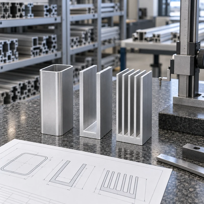
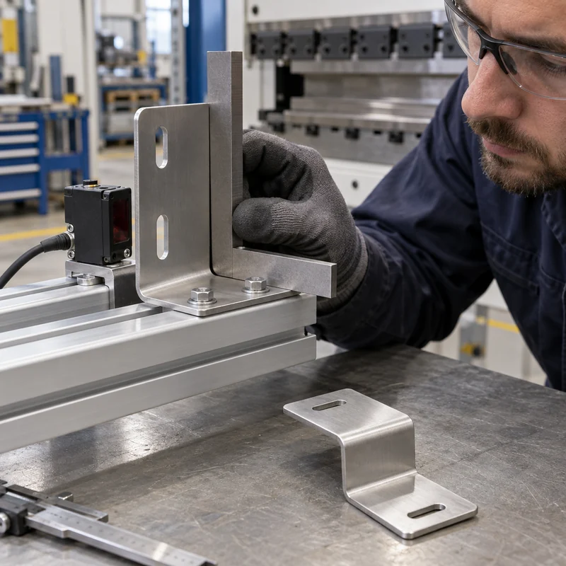
An L bracket offers two perpendicular mounting faces. A U form can support a component between two legs. A Z form creates an offset, while a hat or channel section can increase bending stiffness compared with a flat strip. These names describe geometry rather than a guaranteed load capacity.

Consider bends, returns, ribs, or separate supports before simply increasing thickness. Additional geometry can improve stiffness, but may introduce tooling restrictions or obstruct installation. Check the complete assembly, including the space required to insert and tighten each fastener.

Choose Material Grade and Condition

Material family Reason to consider it Design question
Carbon steel Useful strength and economical fabrication What corrosion protection and finish are required?
Stainless steel Corrosion resistance in suitable environments Which grade and condition suit bending and service?
Aluminum Low mass and suitable corrosion performance Is the selected alloy and temper appropriate for the bend radius?

State thickness and tolerance, alloy or grade, temper or condition, and finish. Different aluminum tempers and stainless grades can behave differently during forming. Check material availability before designing around an unusual thickness that complicates sourcing.

Agree Bend Radius and Minimum Flange With the Shop

The achievable bend depends on material, thickness, grain direction, tooling, and forming method. A flange must be long enough to engage the tooling and allow the operation. A tight return or closely spaced bend can create a tool collision even when each bend is individually feasible.

Protolabs’ published guidance illustrates that bend geometry and feature placement are process-dependent. Use the actual fabricator’s rules for production. Define whether inside radius is a controlled functional requirement or may follow approved standard tooling, and keep equivalent bends consistent where practical.

Move Holes Away From the Bend-Deformation Zone

A hole or slot close to a bend can stretch, shift, or become distorted. Review feature distance using the selected radius, thickness, and tooling. If a critical hole must sit close to a bend, discuss a relief feature, a changed sequence, or post-forming machining.

Bend reliefs can reduce tearing and control the transition where a bend ends. Their geometry should allow the tooling and material to form cleanly without leaving a sharp, unsafe projection or an unacceptable stress concentration. Treat reliefs as part of the functional design.

Plan Fasteners and Tool Access in Three Dimensions

Model screw heads, nuts, washers, captive hardware, mating parts, and installation tools. Check the path for bringing components together, not just the final position. A fastener may fit in the completed model while remaining inaccessible to a socket or driver.

For self-clinching hardware, use the hardware manufacturer’s requirements for sheet thickness, hole size, edge distance, material hardness, and installation. For tapped features, verify available thread engagement. A separate nut or a machined insert may be more suitable than a short thread in thin sheet.

Control Functional Dimensions Without Overconstraining the Drawing

Choose datums that match how the bracket mounts. Focus tolerances on the interfaces that matter: locating holes, mounting planes, offset, angle, or a clearance envelope. Do not apply a tight general tolerance to every formed edge when only one interface requires precision.

Bend-angle variation accumulates over distance, so a small angular difference can produce a larger displacement at a long flange tip. If the application requires a precise final relationship, agree an inspection setup and consider a finishing operation or an adjustable interface.

Where a bracket needs critical bores or datum surfaces beyond the forming route, discuss secondary machining of mounting features. Provide the formed blank and finished requirements together so clamping and stock can be reviewed.

Include Finish and Edge Condition in Fit Checks

Paint, powder coating, plating, and anodizing can affect holes, slots, electrical contact areas, and cosmetic expectations. Define masking where needed and specify whether dimensions apply before or after finish. Coating buildup can interfere with a close slot even when the unfinished bracket passes inspection.

Remove hazardous burrs and define acceptable edge treatment. Where electrical bonding matters, coordinate contact surfaces and corrosion protection with the responsible designer. The surface treatment overview helps compare mechanical finish requirements before release.

Validate the Bracket in Its Real Assembly

Inspect first articles using the mounting condition defined on the drawing. Confirm holes, angles, clearances, fastener access, and the order of assembly. Avoid forcing a flexible part flat during inspection unless that restraint represents the specified mounting condition.

Test representative loading and vibration where the application requires it. If a prototype is made by a different process, verify that it still represents the production material, bend condition, and joint behavior. Keep approved deviations visible rather than relying on a successful hand-fit sample.

Frequently Asked Questions

What bend radius should I use?

Use a radius supported by the selected material, condition, thickness, tooling, and application. Obtain the fabricator’s recommendation before final release.

Can I place a hole directly beside a bend?

Sometimes, but deformation and tooling access must be reviewed. Moving the hole, adding a relief, or machining afterward may be necessary.

Is thicker sheet always the best way to stiffen a bracket?

No. A suitable section shape or shorter load path may improve stiffness more efficiently, subject to strength and manufacturing validation.

What belongs in the quotation package?

Supply the formed model, drawing, material, finish, quantity, functional datums, loads, and acceptance requirements. Confirm the appropriate manufacturing scope through the engineering enquiry page.
Categories
Blog Manufacturing Process Comparisons

3D Printed Tooling: Choosing Printed, Machined, or Hybrid Fixtures

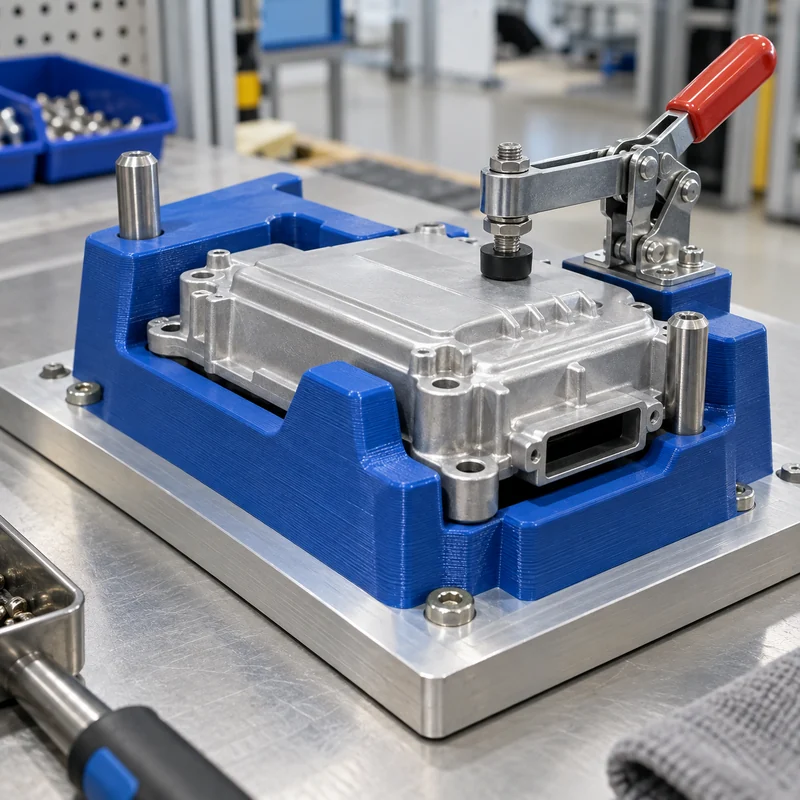
3D printed tooling is useful when a manufacturing aid needs complex contact geometry, quick revision, or low weight. CNC machined tooling is often the stronger candidate when sustained load, wear, heat, or a demanding locating interface controls the design. A hybrid fixture can combine a printed nest with machined datums, steel bushings, and replaceable wear components.

The selection should begin with the operation and its acceptance criteria. A tray for arranging components, a drill jig, and a machining fixture can look similar while having very different failure consequences. Compare complete tools that perform the same job rather than comparing material prices alone.

Start With the Operation and the Forces

Document the workpiece, locating sequence, applied forces, operator actions, and expected cycle count. Include the weight of the part, clamp forces, cutting or drilling loads where relevant, and any loads created during unloading. A tool that holds a component securely on a bench may behave differently when mounted vertically or accelerated by automation.

Define the failure modes worth preventing: movement, excessive deflection, crushed contact pads, worn locating holes, loose inserts, or heat distortion. Identify where a displaced component could damage equipment or expose an operator to harm. Select the tool architecture and validation effort to match those consequences.

Distinguish a Jig From a Fixture

A fixture locates and supports a workpiece during an operation. A jig also guides a tool, for example through a drill bushing. This distinction matters because the guide interface may encounter concentrated wear, friction, and forces that an assembly nest never experiences.

Formlabs’ manufacturing guidance describes both as customized production aids. The practical design lesson is to map each interface separately. A comfortable printed handle can be appropriate even when the drill guide, locating pin, and base plate require metal. Select a construction by function rather than requiring every feature to use one manufacturing process.

Compare the Three Tooling Routes

Route Useful characteristics Items to validate
Printed polymer tool Complex nests, low weight, rapid geometry changes Orientation, creep, heat, chemical exposure, surface wear
Machined metal tool Rigid bases, durable datums, accessible precision interfaces Clamping distortion, mass, corrosion, machining access
Hybrid assembly Printed geometry combined with durable locating and guiding elements Insert retention, tolerance accumulation, replaceability, joint stability

No row guarantees a particular tolerance or service life. Those outcomes depend on material, geometry, processing, inspection, and use. Compare the actual proposed constructions, including post-processing and any machining, rather than a generic label such as engineering resin or aluminum.

Design Datums and Support Before Adding Clamps

Choose repeatable locating features that constrain the intended motion without unnecessarily overconstraining the workpiece. Place supports under locations that carry clamp or process loads. A clamp acting between distant supports can bend the part and create a false inspection result.

Provide clearance for burrs, debris, and nonfunctional surfaces. Do not let a large cosmetic surface accidentally become the locating datum unless the drawing permits that approach. Where the operation needs accurate reference features, discuss machined base plates and locating surfaces early enough to coordinate them with the nest.

Treat Printed Orientation as a Design Variable

Printed properties and surface quality can depend on build orientation, layer bonding, support placement, and post-curing or conditioning. Avoid assuming that a material datasheet represents every direction in the finished tool. Ask the supplier which surfaces need supports and how their removal affects the workpiece contact.

Allow for the processing sequence. An insert installed into a thin boss can split or distort it; a threaded connection repeatedly tightened into polymer can lose retention. Provide sufficient surrounding material and validate the selected insert installation method using representative samples. There is no universal wall thickness that qualifies every tool.

Put Metal Where Wear and Contact Demand It

Steel drill bushings, locating pins, threaded inserts, and replaceable pads can protect a printed body from repeated contact. The interface holding those components matters as much as the components themselves. Define whether the fit is pressed, bonded, mechanically retained, or assembled through a separate metal structure.

Keep the load path understandable. For a hypothetical assembly nest, a printed shell might position a cosmetic housing while a metal stop reacts the clamp force. That arrangement needs a review of the housing support and stop position; adding a steel pin alone does not make the entire fixture rigid.

Check Heat, Coolant, Cleaning, and Time Under Load

Service conditions can overturn an otherwise attractive tooling choice. Exposure to cleaning agents, oils, humidity, ultraviolet light, soldering heat, or hot components should be considered using the actual material and exposure duration. A brief temperature rating cannot establish long-term dimensional stability.

Also review creep under sustained clamping and the temperature reached during repeated cycles. A fixture left loaded overnight may behave differently from a tool released after each short operation. Record the intended cleaning method and storage condition alongside the operating instructions.

Validate the Tool Against a Measurable Acceptance Plan

Inspect the locating features before loading a part, then verify the part position under the intended clamp condition. Run representative cycles and inspect again for movement, wear, loose hardware, and permanent deformation. Compare repeated load and unload measurements where repeatability controls the process.

For inspection fixtures, assess the contribution of the tool and operator to measurement variation. For production aids, agree the permissible workpiece movement and part quality results. The inspection planning resources provide context for defining critical features and reports with MTSPi.

Compare Lifetime Cost and Revision Risk

Include design, printing or machining, hardware, finishing, inspection, validation, downtime, repairs, and replacement in the comparison. A low initial cost may be attractive for a frequently revised prototype, while a stable production line may justify durable replaceable wear surfaces.

Freeze the approved CAD revision and material specification after validation. Mark tools so operators can distinguish old and new versions. Maintain spare wear components when replacement time affects production, and revalidate meaningful changes in build orientation, material, or supplier.

Frequently Asked Questions

Can a printed fixture replace an aluminum fixture?

Sometimes. Compare stiffness, load, temperature, wear, repeatability, and lifetime requirements using a representative tool and operation.

Can drill bushings be installed in printed tooling?

Yes, with a suitable retention design. Validate alignment, local support, retention, and wear under the intended drilling conditions.

What should I send for a tooling quote?

Send the workpiece model and drawing, operation description, datums, loads, environment, cycle expectations, and acceptance requirements. Confirm the proposed mechanical scope through the project contact page.

Categories
Blog Design, Cost & Sourcing

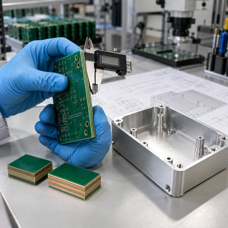
FR4 PCB Material: Specifications, Grades, and Enclosure Design

FR4 PCB material is a family of glass-reinforced epoxy laminates, not one interchangeable specification. A useful purchasing package names the laminate or performance class, finished thickness, copper weights, stackup, surface finish, impedance requirements, compliance requirements, and the tests used for acceptance.

This guide explains how to turn “FR4” into a quote-ready material requirement and how that choice affects a machined enclosure. MTSPi manufactures mechanical parts; it does not claim PCB fabrication capability. Confirm laminate, fabrication, and electrical-test requirements with the selected board supplier.

What FR4 Means and What It Does Not

FR4 describes a flame-retardant grade family commonly based on woven glass reinforcement and epoxy resin. It does not identify one resin system, one glass-transition temperature, one dielectric constant, or one approved operating temperature. Two materials described as FR4 can have materially different thermal and electrical properties.

A flame-retardant grade is also not a substitute for a product-level compliance decision. When a flame classification matters, request the laminate manufacturer, exact product designation, relevant UL file, minimum thickness covered, and the board fabricator’s applicable recognition. Do not infer approval from the green color of a finished board.

Use the Datasheet, Not a Generic FR4 Number

Published laminate data show why a generic callout is incomplete. For example, an Isola low-Tg FR4 product lists a 135 C Tg, while a high-Tg FR4 product lists a 180 C Tg. Their decomposition temperature, Z-axis expansion, moisture absorption, dielectric properties, and copper options also differ. These values belong to the named products and test methods; they are not universal FR4 constants.

Property What it describes Why a buyer cares
Tg Transition in the resin system’s mechanical behavior Useful for thermal-process and dimensional-stability review, but not a maximum service-temperature rating
Td Decomposition temperature under a stated test method Helps compare resistance to thermal degradation; it does not replace reflow qualification
Z-axis CTE Expansion through the board thickness Relevant to plated-through-hole and multilayer reliability during thermal cycling
Dk Relative permittivity at a stated frequency and method Affects transmission-line geometry and propagation; use the fabricator’s design value
Df Dielectric loss at a stated frequency and method Matters when insertion loss and high-frequency performance are design constraints
CTI Comparative tracking index under a defined test May influence insulation coordination, but required creepage still depends on the applicable safety standard
Water absorption Moisture uptake under a stated conditioning method Can affect processing, dimensional behavior, and electrical performance

Do not compare isolated values measured by different methods as if they were directly equivalent. Record the test method, frequency, conditioning, and whether a value is typical or guaranteed.

Specify the Thermal Requirement as a Process Window

“High Tg” is useful shorthand only after the assembly process is known. Document the soldering profile, number of expected thermal excursions, board thickness, copper distribution, via construction, and reliability requirement. Tg, Td, time-to-delamination data, and expansion behavior answer different questions.

For lead-free assembly, ask the fabricator to propose a laminate qualified for the agreed stackup and reflow exposure. A high Tg alone does not guarantee low Z-axis expansion, adequate time to delamination, or a robust plated-through-hole construction. If the board will operate hot after assembly, treat continuous operating temperature as a separate application requirement.

Define the Electrical Requirement Before Naming a Substitute

Standard FR4 may be suitable for many digital and low-frequency products, but there is no defensible universal frequency at which it suddenly stops working. Trace length, loss budget, edge rate, impedance tolerance, copper roughness, weave effects, temperature, and moisture all influence the result.

For controlled impedance, provide the target, tolerance, layer reference, and test-coupon requirement. Let the PCB fabricator close the stackup using the actual laminate and copper system, then return the proposed geometry for electrical approval. The HDI stackup and mechanical-integration guide shows how to coordinate that proposal with the enclosure revision.

Move to a characterized low-loss or RF laminate when analysis shows that FR4’s loss or property variation consumes the available margin. Use a metal-core construction when heat spreading dominates and the electrical design supports it. Use a flex construction when the circuit must bend. These are requirement-driven changes, not automatic upgrades.

Make Thickness and Copper Unambiguous

A nominal finished thickness such as 1.6 mm does not define the dielectric structure. State the finished-thickness tolerance, layer count, copper weight by layer, plating assumptions, and approved stackup. If connector fit, card guides, edge contacts, or a compression interface depend on thickness, identify that dimension as a mechanical interface.

Copper should be stated as starting and/or finished copper where relevant. A plated outer layer does not necessarily finish at its starting foil thickness. Heavy copper changes etching, spacing, thermal behavior, and stackup balance, so it belongs in the first quotation package rather than a later note.

Choose Surface Finish From Assembly and Storage Needs

Surface finish affects solderability, pad flatness, storage, rework, and cost. Lead-free HASL, ENIG, OSP, immersion silver, and other options are not interchangeable defaults. Fine-pitch components may need a flatter finish, while storage duration and handling conditions can rule out an otherwise economical option.

Ask the assembly supplier to approve the finish together with the component package and soldering process. If edge contacts, wire bonding, repeated mating, or a specific shelf-life requirement applies, state it explicitly and request the appropriate thickness and inspection evidence.

Coordinate the PCB With the Machined Enclosure

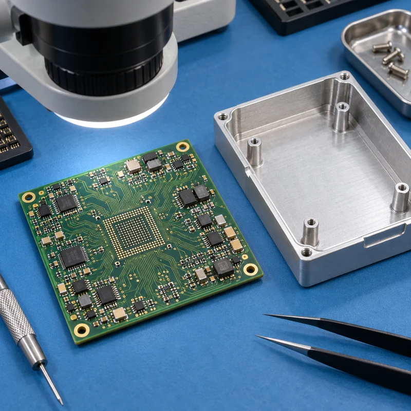
The laminate choice reaches the enclosure through finished thickness, bow and twist, mounting-hole location, connector position, thermal-interface compression, and electrical clearance. A CAD model containing only the bare board outline is not enough for a reliable fit review.

  • Use shared datums for the board holes, enclosure standoffs, and connector openings.
  • Model maximum component height, keep-out zones, screw heads, washers, and cable bend space.
  • Define the acceptable board-thickness range where card guides or edge slots locate the assembly.
  • Review thermal-pad compression without forcing the PCB to become a spring.
  • Keep conductive hardware and machined bosses outside the electrical team’s required clearances.
  • Inspect first-article board-to-housing fit with the populated assembly or a controlled representative fixture.

Send the approved board envelope and interface drawing when discussing machined enclosure features. MTSPi can review the mechanical component, tolerances, material, and inspection scope without representing the PCB fabrication itself.

A Quote-Ready FR4 PCB Specification Checklist

RFQ field Minimum useful content Evidence to request
Laminate Manufacturer/product or approved performance class; Tg/Td/CTE and compliance requirements Datasheet, certificate of conformance, UL file where applicable
Construction Layer count, proposed stackup, finished thickness and tolerance Approved stackup drawing and revision
Copper Per-layer starting/finished requirement as applicable Stackup and cross-section plan
Electrical Impedance targets and tolerances, test coupons, net test requirement Impedance report and electrical-test record
Thermal process Assembly profile, expected cycles, and special operating environment Material suitability confirmation and agreed qualification
Finish Named finish, thickness where relevant, storage/assembly constraints Process certificate or inspection result as required
Mechanical Outline, hole tolerances, bow/twist limit, connector and enclosure interfaces First-article dimensional report
Compliance Applicable IPC class, RoHS/REACH or product-specific requirements Agreed certificates and traceability documents

Include Gerber or ODB++ data, drill files, fabrication drawing, stackup, netlist where required, assembly constraints, and revision identifiers. Ask suppliers to list every proposed deviation instead of silently substituting an available laminate.

When to Stay With FR4 and When to Switch

Stay with a qualified FR4 product when its documented electrical, thermal, mechanical, regulatory, and supply requirements fit the application. Consider a higher-performance laminate when repeated thermal processing or reliability requirements exceed the proposed standard material. Consider low-loss/RF material when simulation and test budgets require tighter and lower dielectric loss. Consider metal-core material for a heat-spreading architecture, polyimide-based flex for controlled bending, or another substrate when the product requirement clearly demands it.

The correct decision is the least exotic material system that passes the complete requirement set with manufacturing margin. A premium laminate cannot repair an incomplete stackup, poor thermal design, or an enclosure that loads the board incorrectly.

Frequently Asked Questions

Is all FR4 the same?

No. FR4 is a grade family. Resin systems, Tg, Td, expansion, moisture absorption, Dk, Df, approvals, and available constructions vary by product.

Does a higher Tg automatically mean a better PCB?

No. It can support certain thermal requirements, but reliability also depends on expansion, decomposition behavior, stackup, via construction, process control, and the actual thermal cycle.

Can I specify only 1.6 mm FR4 and 1 oz copper?

That is enough for a rough budgetary discussion, not a controlled build. Add the exact or approved laminate class, stackup, finished-thickness tolerance, copper definition, surface finish, electrical requirements, and acceptance tests.

At what frequency must FR4 be replaced?

There is no universal cutoff. Use the channel loss budget, trace length, material data at the relevant frequency, impedance tolerance, environment, and validation results to decide.

What should the enclosure supplier receive?

Provide the approved board outline, thickness range, hole and datum scheme, populated height envelope, connector locations, keep-outs, thermal interfaces, and assembly sequence. Use the engineering contact page to submit the mechanical package for review.

Technical reference basis: IPC technical resources on laminate thermal behavior and moisture; published Isola FR4 laminate data; UL material-recognition records; Rogers guidance on high-frequency laminate selection. Values in this article are explanatory only. Use the named product’s current datasheet and the applicable design standard for procurement.

Categories
Blog Manufacturing Process Comparisons

Large Format 3D Printing: Design, Joining, and CNC Finishing

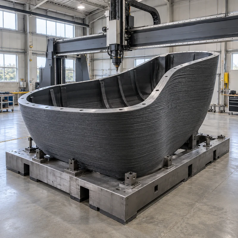
Large format 3D printing produces oversized components using a suitable additive process, sometimes followed by joining and CNC finishing. The useful question is not simply whether a model fits inside a printer. It is whether the complete manufacturing route can deliver the required interfaces, stability, surface condition, and inspection evidence.

This guide focuses on polymer components and tooling. Metal additive manufacturing has different equipment, support, thermal-processing, and qualification requirements. Neither route should be selected from a machine’s advertised build volume alone.

Define the Finished Part Before Choosing a Machine

Separate the overall shape from the functional interfaces. A full-size appearance model may accept visible layer lines. A fixture may need accurate locating pads. A mold may require a qualified working surface and temperature capability. These are different acceptance problems even when the outer dimensions are similar.

List the supplied dimensions, transport envelope, service environment, assembly loads, and surfaces requiring measurement. Identify the part’s inspection condition: unsupported, located on datums, or held in an assembly fixture. A large compliant shell can produce different measurements under different restraints.

Match the Process to the Entire Manufacturing Route

Route Reason to consider it Question before quotation
Large filament extrusion Full-scale polymer prototypes and suitable functional parts Can the selected material and geometry be produced without unacceptable distortion?
Pellet-fed extrusion Large near-net shapes with substantial material deposition What machining and finishing steps are included?
Large resin printing Detailed models or patterns where the chosen resin is suitable How are supports, curing, and dimensional acceptance controlled?
Sectioned assembly Parts exceeding a practical build or handling envelope How will the joints be located, inspected, and qualified?

Manufacturer specifications must be checked for the particular machine and material. There is no single build-size limit or tolerance that applies to an entire process family. Large-printing equipment also differs in its thermal controls and processing workflow.

For context on the broader alternatives, see the requirement-based process comparison. An attractive process name cannot replace a review of the actual part.

One Piece or Several Sections?

A one-piece build avoids assembly joints but can create a long, expensive job with demanding handling and finishing requirements. Dividing the part can improve access and allow smaller sections to be replaced, but adds alignment work and another source of variation. Neither choice is automatically cheaper.

Compare both routes against the same finished specification. Include the time required for adhesive preparation and cure, fastening, surface blending, alignment fixtures, and final inspection. Consider where the completed component will be installed: a part that fits the printer but not the building access route creates a separate logistics problem.

For a hypothetical equipment cover, a split near a removable service panel might be acceptable while a seam across a prominent cosmetic face is not. For a loaded tool, joint placement needs an engineering review of the load and temperature conditions. Appearance alone is not a sound basis for locating that joint.

Design Joints as Functional Features

Provide a defined locating method rather than relying on a long butt joint to align itself. Depending on the application, mating steps, dowels, fixtures, or designed fastening features may help establish position. Agree which features carry load and which only locate the assembly.

  • For bonded joints, validate material compatibility, preparation, bond geometry, and cure conditions.
  • For fastened joints, check local wall support, access, preload effects, and repeated assembly requirements.
  • For thermoplastic welding, confirm material and process compatibility with a qualified supplier.
  • For every joint, define the acceptance method and permissible mismatch.

There is no universal strength ranking between adhesives, fasteners, and welded joints. Geometry, material condition, temperature, and loading direction all matter. Use representative testing where the failure consequences justify it.

Reserve CNC Finishing for the Surfaces That Need It

Thermwood describes a near-net-shape workflow in which a part is printed oversize and then CNC trimmed to its final geometry. This is a useful manufacturing strategy, not a promise that any print can achieve any tolerance through machining.

Identify the mounting pads, sealing faces, locating holes, or other interfaces that require finishing. Define machining allowance with the manufacturing team, allowing for the selected print route and anticipated variation. Avoid removing so much stock that a cutter exposes an unsuitable internal structure or leaves a wall below its functional thickness.

Plan how the blank will be held. Clamping against a flexible printed wall can alter its shape, so the measured result in the fixture may differ from the released part. Datums, supports, cutter access, and tool travel need to be reviewed together. A part fitting the printer does not guarantee it fits the subsequent machining setup.

Discuss the critical interfaces and blank condition when requesting secondary milling of functional surfaces. Confirm material suitability and machine capacity with MTSPi before committing to a production route.

Validate Behavior at the Intended Scale

A small sample can help compare surfaces or basic material behavior, but it does not demonstrate the dimensional stability of a much larger geometry. Long spans, uneven section thickness, handling supports, and the sequence of processing operations deserve specific attention.

Record build orientation and post-processing conditions for the approved sample. Define the environment and support condition for dimensional inspection. Where elevated temperature or sustained loading matters, qualify the finished construction, including any coating, joint, or insert, rather than assuming that a resin name establishes performance.

Request a Delivered-Part Quote

Compare proposals that include the same scope: printing, material conditioning, support removal where applicable, joining, machining, finishing, inspection, packaging, and transport. Ask which requirements are guaranteed, which depend on a trial, and which require a design change.

A low print-only price can be misleading if another proposal includes the fixture and finished interface measurements. For interim production planning, the bridge-production acceptance checklist adds useful controls for revision and lot traceability.

Frequently Asked Questions

Does large format have a fixed size definition?

Not one universal threshold across suppliers. Specify actual part dimensions and the complete production route instead of relying on the label.

Must a large print be machined afterward?

No. Some as-printed parts meet their requirements. Machining is useful when selected interfaces need a condition the printing route cannot reliably provide.

Is printing in one piece always stronger?

No. Performance depends on material, build direction, geometry, and loads. A designed and qualified assembly may be suitable; a poorly positioned joint may not be.

Can a printed mold be used at any temperature?

No. Validate the complete tool against its thermal and mechanical duty. Material choice, construction, working surface, and operating conditions must be compatible.

Technical reference basis: Thermwood LSAM near-net-shape documentation and BigRep large-format equipment and design guidance. Examples are illustrative, not claims about MTSPi equipment ownership or documented customer test results.

Categories
Blog Design, Cost & Sourcing

HDI PCB Design: Stackup Decisions and Mechanical Integration

An HDI PCB uses high-density interconnect construction, including microvias and fine routing features, to connect components where conventional routing becomes difficult. It is not defined solely by having many layers. A useful design review connects the electrical stackup to fabrication capability and then checks the assembled board against the enclosure.

This guide addresses engineering handoffs. It does not imply that MTSPi fabricates PCBs or provides a particular electronic assembly certification. Confirm electronic fabrication requirements with the chosen board manufacturer and mechanical component requirements with the machining supplier.

Establish Whether HDI Solves a Real Routing Constraint

Start with the component package, pin map, board outline, routing density, and electrical requirements. A fine-pitch BGA may need a different escape strategy from a larger package with the same logical function. Moving a connector or increasing the board outline may sometimes avoid a costly construction, but those decisions affect the product enclosure and assembly.

Ask the layout engineer to identify the actual bottleneck: insufficient escape channels, excessive layer transitions, limited routing area, or a package geometry that the current via pattern cannot accommodate. “Make it HDI” is not a complete design instruction.

Read the Via Map Alongside the Stackup

Feature Basic role Question to settle
Through via Connects through the board thickness Where does its occupied area restrict routing?
Blind via Connects an outer layer to an internal layer Which layer pair is connected?
Buried via Connects internal layers without reaching an outer surface How is it incorporated into the manufacturing sequence?
Microvia Provides a small, shallow interlayer connection What geometry, filling, and reliability requirements apply?

Do not treat every blind via as a microvia. Supply a layer-pair drawing and define the intended structure. Staggered microvias use offset positions between successive connections; stacked microvias align vertically. They are not interchangeable layout shortcuts. Discuss the specific construction, process capability, and qualification evidence with the fabricator.

Industry HDI design guidance, including Altium’s manufacturing guide, emphasizes that the via structure and manufacturing sequence belong in the design discussion. A visually complete CAD layout does not by itself establish that a shop can manufacture and inspect the intended interconnect reliably.

Select a Manufacturable Build-Up Before Detailed Routing

A notation such as 1+N+1 generally describes one build-up layer on each side of an N-layer core structure. It is a shorthand, not a complete procurement specification. Copper weights, dielectric materials and thicknesses, layer functions, via connections, finished thickness, and impedance requirements still need definition.

Eurocircuits’ published HDI guidance illustrates an important approach: begin with an available build-up and its design rules. Its partial-HDI examples also show that fine routing can be concentrated in part of a construction rather than assumed to require the most complex stack everywhere. Those are supplier-specific offerings, not universal dimensions to copy into an unrelated purchase order.

Agree impedance targets with the actual material and layer structure. Track width alone is insufficient: reference-plane spacing, dielectric properties, copper thickness, and differential-pair spacing all contribute. The board fabricator’s stackup proposal and the designer’s electrical constraints must refer to the same revision.

Check the Mechanical Envelope in Three Dimensions

A smaller board is not automatically a smaller finished product. Connectors, cable bends, component height, thermal hardware, fastening access, and assembly order may control the envelope. A dense board can fit its outline perfectly and still interfere with the enclosure lid.

  • Define a common coordinate origin and mounting-hole datums.
  • Check maximum component height on both sides of the PCB.
  • Include connector mating travel and cable exit space.
  • Keep fasteners and standoffs clear of copper and components as required by the electrical design.
  • Review thermal-pad contact without bending the board through excessive compression.
  • Check access for assembly tools and any required rework.

For an illustrative fit study, export the populated board into the mechanical assembly, add the intended screw heads, and sweep the connector’s mating motion. This can expose a conflict that a bare-board outline check misses. Measure the critical physical interface on first articles instead of relying only on nominal CAD alignment.

Programs using flexible interconnects should also review bend-zone and enclosure-fit considerations. These are separate mechanical constraints, not benefits automatically provided by HDI construction.

Prepare Two Coordinated Manufacturing Packages

The PCB package should contain the agreed fabrication data, layer map, drill and via definitions, stackup, material requirements, finish, impedance targets where applicable, and inspection or test requirements. The mechanical package should contain the enclosure model, drawing, datums, finish, mounting geometry, and approved board envelope.

Use a release table linking both packages to the same assembly revision. If the board thickness changes after quotation, notify the mechanical team: connector height or a retaining feature may depend on that value. Likewise, an enclosure standoff change should not be implemented without checking the populated board.

Discuss machined housing features with MTSPi using the board envelope and interface drawing. Use the project contact page to confirm mechanical scope and required evidence.

Compare Supplier Proposals on Evidence

Request explicit confirmation of the proposed via construction and any departures from the submitted stackup. Compare inspection, electrical testing, documentation, change control, and lot identification rather than accepting “HDI capable” as the complete answer. Acceptance standards and their applicable editions should be agreed in the purchase specification.

Keep electrical continuity, structural reliability, and assembly fit as separate verification questions. A board that passes one check has not necessarily passed the other two.

Frequently Asked Questions

Is every multilayer PCB an HDI board?

No. Layer count alone does not establish HDI construction. Interconnect technology and routing requirements matter.

Can I select microvia sizes after routing?

That risks significant rework. Select the fabricator’s supported stackup and rules before detailed routing.

Does HDI guarantee better signal integrity?

No. Layout, reference planes, materials, transitions, and manufacturing tolerances still require electrical analysis.

Why involve the enclosure supplier early?

The mounting interfaces, component heights, connector positions, and thermal contacts must work together in the finished assembly.

Technical reference basis: Eurocircuits HDI build-up and design guidance; Altium HDI PCB Design and Manufacturing Guide. Mechanical handoff examples are illustrative, not reported customer projects.

Categories
Blog Design, Cost & Sourcing

Aluminum Extrusion Design: A DFM Checklist Before Die Release

A manufacturable aluminum extrusion design balances section geometry, alloy, tolerance, and downstream operations before the die is released. The goal is not merely to push a profile through a die. It is to produce stock that can be cut, held, machined, finished, inspected, and assembled without repeated correction.

If the cross-section type is still undecided, begin with the comparison of extrusion profile shapes. This guide focuses on the next decision: whether a specific custom section is ready for tooling.

Start With the Assembly Interface, Not a Minimum Wall Number

Identify the surfaces that locate the component, carry load, seal against another part, or remain visible. Mark the assembly datums on the drawing. An external envelope may tolerate more variation than a sliding channel or a machined bearing seat, so applying one tight tolerance to the whole section is usually an unhelpful starting point.

There is no universal minimum wall thickness that is suitable for every alloy, press, profile width, or hollow feature. Ask the extruder to review the actual section. Document the intended alloy and temper, supplied length, annual demand, cut length, finishing route, and any restrictions on profile changes.

Review the Section for Balanced Flow and Robust Tooling

The Aluminum Extruders Council recommends balanced wall thickness and provides design guidance on section geometry. In practice, review abrupt transitions between thick and thin regions, sharp corners, and slender unsupported die features. Smooth transitions and sensible radii can improve feasibility, but the final dimensions must be agreed with the toolmaker.

Design feature Question for review Possible direction
Thick base with very thin fins Can the section be produced consistently? Rebalance section geometry with thermal and structural analysis
Deep narrow channel Does the opening require a fragile die feature? Widen access or reconsider the channel arrangement
Abrupt section change Can the transition be softened? Introduce a compatible radius or gradual change
Critical close-fitting slot Is extrusion tolerance sufficient after finishing? Reserve a controlled machining operation if necessary
Thin clamping wall Will machining restraint distort it? Provide supported locating and clamping surfaces

Each change has a functional tradeoff. A thicker fin may improve manufacturability while changing heat transfer or mass. Do not approve a die-driven geometry change without checking the original design requirement.

Separate As-Extruded and Machined Requirements

Extrusion standards address more than width and height. Straightness, twist, wall thickness, and other geometric characteristics can matter across a supplied length. The AEC tolerance resources direct designers to relevant industry standards; the drawing and purchase agreement should identify the applicable requirements rather than simply asking for “precision extrusion.”

Create two explicit states when appropriate: the purchased profile and the finished component. A bolt pattern machined after cutting should be controlled from finished-part datums. A long as-extruded surface may need a different inspection setup than the local interface machined into it.

For example, a housing rail might use its bottom face as the finished assembly datum. If the blank is held from an uncontrolled side wall, the hole pattern may be repeatable in the fixture but misplaced relative to the mating base. That is a datum-planning problem, not a reason to tighten every extrusion dimension.

Design the Machining Setup Before Approving the Die

Check tool access, available clamping area, cut-off allowance, burr removal, and access for inspection. A profile that looks efficient in cross-section may require multiple setups to drill inaccessible features. A small geometry change can sometimes simplify the entire route.

  • Identify which surfaces will locate the blank during each operation.
  • Confirm whether thin walls need support under clamping loads.
  • Specify machining allowance where cleanup is required.
  • Review access for cutters, drills, taps, and deburring tools.
  • Define which dimensions are accepted before and after finishing.

Submit the profile model and finished-part drawing together when discussing secondary milling and drilling. The unmachined stock definition alone is not enough to quote the finished part reliably.

Include Finish and Cosmetic Requirements in the Review

Anodizing, coatings, and mechanical finishing affect the acceptance plan. Mark visible faces and agree the reference sample, permitted marks, masking requirements, and inspection condition. Where fit is sensitive, evaluate the selected finish’s dimensional effect with the finishing supplier instead of assuming a universal coating allowance.

Keep engineering finish requirements separate from aesthetic descriptions. “Silver finish” does not specify an anodizing process, thickness requirement, sealing requirement, or color tolerance. The surface-treatment overview can help structure the finishing discussion.

A Practical Die-Release Gate

Before authorizing tooling, ask the responsible parties to sign off the same drawing revision. Record open issues with an owner and disposition rather than relying on comments spread across email attachments.

  1. Function: critical interfaces and loads are identified.
  2. Feasibility: the extruder has reviewed the complete section, alloy, and tolerances.
  3. Operations: cutting, machining, finishing, and inspection routes are defined.
  4. Acceptance: first-article scope, sample requirements, and change approval are agreed.
  5. Commercial scope: die ownership, maintenance, minimum order, and revision costs are clarified.

This review does not eliminate trials. It makes the trial meaningful by defining what must be demonstrated and which deviations require approval.

Frequently Asked Questions

Should all profile walls be identical?

Balanced walls are a useful design objective, not an absolute rule. Functional needs may require differences that the extruder must evaluate.

Can extrusion replace every machining operation?

No. Features that vary along the length, cross holes, precision seats, or local pockets commonly require secondary operations.

Can I specify machining tolerances on the full extrusion?

Discuss each functional requirement with the supplier. A finished tolerance may require machining rather than being economical or feasible directly from extrusion.

What files should accompany an RFQ?

Provide the section drawing, 3D model, finished-part drawing, alloy and temper, finish, volumes, and inspection requirements.

Technical reference basis: Aluminum Extruders Council design tips, design considerations, and tolerance resources. Workflow examples are illustrative and require supplier-specific feasibility review.

Categories
Blog Manufacturing Process Comparisons

3D Printing for Low-Volume Production: A Bridge-to-Molding Plan

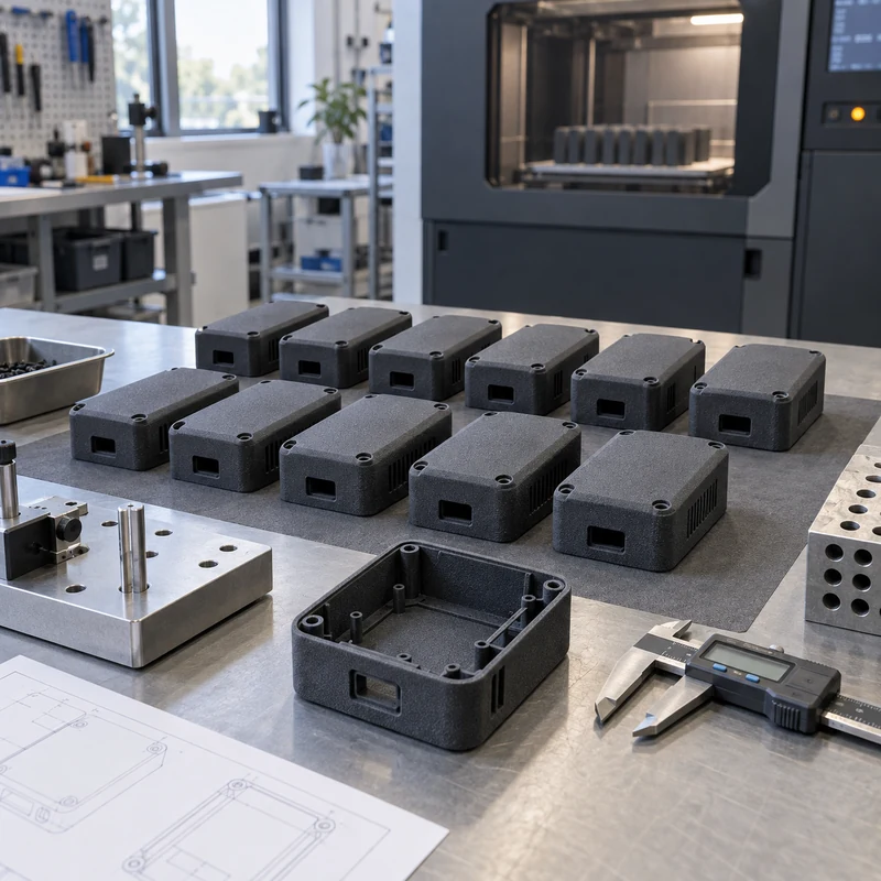
3D printing can supply a low-volume production batch while an injection mold is being developed, provided the printed material, process, and inspection plan are approved for the actual use. A successful bridge-production plan defines what may ship, how each batch will be accepted, and when the program will change to molded parts. It is not simply a larger prototype order.

Decide What the Interim Parts Must Prove

Start with the consequence of failure. A display housing for an internal sales review does not have the same requirements as a customer-delivered enclosure exposed to heat, sunlight, cleaning chemicals, or repeated screw assembly. Write down the operating environment and the release authority before selecting a printer or material.

Intended use Useful acceptance evidence Do not assume
Appearance review Approved color and surface sample Printed texture reproduces molded texture
Assembly trial Mating-part checks and measured interfaces One fit check establishes production capability
Functional pilot Application-specific load and environmental tests A similarly named resin has identical properties
Customer shipment Approved specification, lot records, release inspection A prototype approval covers end-use shipment

Where certification or regulated use applies, confirm which manufacturing changes require additional qualification. A material datasheet alone does not establish compliance of a finished assembly.

Choose the Process Against the Failure Mode

SLA, SLS, MJF, and material-extrusion processes can address different combinations of appearance, geometry, material behavior, and throughput. Compare candidate processes using the same part and inspection criteria rather than a generic claim about the strongest or cheapest technology. The requirement-based printing process comparison provides a starting framework.

Orientation affects printability, support placement, finish, and dimensional results. The printer manufacturer’s validated guidance should inform the build setup. Keep supports away from critical cosmetic or mating surfaces where practical, and include cleaning and post-curing when the selected system requires them. Lock the approved build recipe before interpreting results from multiple deliveries as comparable.

Do not substitute an SLA resin described as ABS-like for molded ABS without checking the properties relevant to the application. Repeated flexing, long-term temperature exposure, creep, and chemical resistance may decide suitability even when both samples initially fit.

Compare Total Accepted-Part Cost

There is no universal quantity at which molding becomes cheaper. Use supplier quotations for the same revision and include tooling, setup, finishing, inspection, expected scrap, and delivery. A simple preliminary model is:

Break-even quantity = (mold tooling and setup cost minus print setup cost) / (accepted printed-part cost minus accepted molded-part cost).

This expression is useful only when the denominator is positive and the compared parts satisfy the same requirements. For an illustrative calculation, a tooling difference of $8,000 and a unit-cost difference of $16 gives 500 accepted parts. Those figures are invented planning inputs, not MTSPi pricing. A design revision that changes the tool, or a finishing operation omitted from one quotation, can invalidate the comparison.

Separate economics from availability. Printing may remain appropriate for a time-critical interim batch even when molding has a lower eventual unit cost. For a broader quotation checklist, review the factors behind printing and scale-up cost.

Make Each Batch Traceable

Printed parts can have effective traceability; it must be specified and maintained. A useful traveler connects the part revision to material lot, machine, build identifier, approved orientation, post-processing records, inspection results, and release date. Decide whether individual serialization or batch identification is needed.

  • Approve a representative sample before the first production release.
  • Identify critical dimensions and how they will be measured.
  • Agree sampling frequency and the response to a failed check.
  • Record build or material changes before shipping affected parts.
  • Retain a reference sample when useful for later comparison.

A hypothetical enclosure program might check mounting-hole location with a fixture, verify lid engagement with a mating part, and inspect the cosmetic face under agreed lighting. These checks answer different questions. Passing the visual inspection does not replace measuring the mounting interface.

Control the Transition to Molded Production

Maintain a revision-controlled comparison between the interim part and the molded design. Draft, ribs, wall thickness, gate locations, ejection marks, and shrinkage behavior require a molding-specific review. A printed prototype that assembles successfully does not prove that the same geometry is ready for tool release.

Close the bridge phase after the production process has passed its agreed qualification and supply can meet the schedule. Keep interim and molded stock identifiable when their material or performance differs. Establish disposition for remaining inventory instead of silently mixing both routes under an uncontrolled label.

When planning the surrounding mechanical parts, share the assembly model, tolerances, and expected production sequence with MTSPi through the project inquiry page. Confirm the proposed scope and process with the team rather than assuming every manufacturing route is available.

Frequently Asked Questions

Can printed bridge parts be sold to customers?

Yes, when the material and finished part are qualified for their intended use and the required approvals and traceability are in place. Prototype acceptance alone is insufficient.

Does bridge production always mean printing?

No. The term describes an interim production role. Machining, casting, or temporary tooling may also be suitable, depending on the part and schedule.

Are printed molds the same as directly printed parts?

No. Direct printing creates the component. A printed mold is tooling used to form a separate component, with its own limits on temperature, pressure, wear, and tool life.

Should every small batch avoid injection molding?

No. Required resin behavior, geometry, repeatability, and available tooling can make molding appropriate even for modest quantities.

Technical reference basis: Formlabs model-orientation guidance and injection-molding application documentation. Cost figures and inspection examples are illustrative planning examples, not production test data.

Categories
Blog Design, Cost & Sourcing

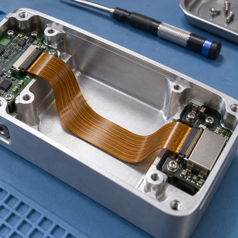
Flexible PCB Design: Bend Zones, Materials, and Enclosure Fit

A flexible PCB places conductive tracks on a thin flexible substrate so an electrical connection can follow a three-dimensional route. Successful flexible PCB design combines electrical requirements with mechanical packaging: a circuit that passes a bench continuity test can still be damaged by a connector, enclosure edge, screw, or repeated movement.

Quick answer: Define the installed route and motion first. Agree the stackup, bend radius, bend zones, stiffeners, and connector interfaces with the circuit manufacturer, then verify the assembled product. Treat the flex circuit and its enclosure as interacting parts throughout the design review.

Choose the Circuit Construction Around Its Job

Construction Why consider it Design question
Single-layer flex Simple interconnections with a thin flexible region Can the routing fit without adding layers?
Double-sided or multilayer flex More routing density and electrical functions Does the complete stack remain suitable for the required bend?
Flex with local stiffeners Supported connectors or component areas Where does the stiffener end relative to the bend?
Rigid-flex assembly Integrated rigid component regions and flexible connections Does integration justify the fabrication and assembly complexity?

Rigid-flex is a distinct construction rather than simply a flexible board with a reinforcing patch. For that option, review the rigid-flex stackup and assembly guide alongside the housing design.

Separate Installation Bends From Repeated Movement

A circuit formed once during installation has a different duty from one moving through thousands of cycles. Vibration or service access can add movement even when the product appears static. Define the movement, expected cycles, temperature, and assembly handling before asking for a minimum radius.

The complete flexible-region thickness includes the copper, dielectric, adhesive where present, and protective layers. Material construction and copper type also affect bending behavior. Obtain a radius recommendation for the actual stackup and duty, rather than applying a universal multiplier to every design.

Make Material Choices With the Fabricator

Polyimide is a common flexible-circuit substrate. Copper construction, coverlay, adhesives, and stiffeners must be selected as a system. Rolled-annealed copper is often considered where flexing performance is important; material selection still needs confirmation for the intended use.

Publish the approved stackup and material requirements with the fabrication data. A part-number change affecting thickness can alter the mechanical fit even if the electrical connectivity remains unchanged. Include the mechanical owner in changes that affect the flexible region or connector thickness.

Reserve Bend Zones in the Layout

Identify bend regions explicitly and coordinate trace routing, vias, components, and stiffener boundaries around them. Avoid forcing the circuit to bend at a sudden rigid transition. Ask the manufacturer to review the combination of routing and mechanical constraints before releasing the files.

A convenient approach is to include both a flat circuit outline and the installed shape in the design package. The flat view defines manufacturing geometry; the installed view communicates where the circuit travels and what occupies the surrounding space. Keep their revision identifiers synchronized.

Design the Enclosure Around the Installed Circuit

Model the circuit’s occupied volume rather than a zero-thickness line. Include the bend, adjacent components, connector access, and the space needed during installation. Provide an intentional route that does not depend on an assembler pressing the loop into an arbitrary corner.

  • Keep the circuit clear of screw tips and closing cover edges.
  • Remove burrs and review edges where contact is possible.
  • Provide access to operate the connector latch.
  • Allow installation without pulling on the conductor region.
  • Check the circuit position with the cover fully closed.

For a machined housing, discuss those details with the CNC milling team. Rounded features, suitable surface treatment, and accessible assembly geometry belong on the controlled housing drawing.

Use a Clearance Budget Instead of a Visual Guess

Consider an illustrative assembly with a nominal 1.5 mm gap between a flex loop and a cover. If housing variation, circuit positioning, and installation variation can each consume 0.3 mm in the unfavorable direction, the simple worst-case remaining gap is 0.6 mm. This example is not a recommended clearance; it demonstrates why nominal CAD separation alone is insufficient.

Add the actual tolerances and motion from your product. Check whether the assembly has a defined locating feature or whether the circuit can wander. When position is uncontrolled, improving the route or retention can be more effective than tightening a machining tolerance.

Prototype the Assembly Sequence

Build a fit model early enough to move the connector or change the housing. Record how the circuit is inserted, latched, formed, inspected, and serviced. A design that fits after difficult manipulation can still fail in repeat production.

Use prototype enclosures and fixtures to evaluate access and routing. Use representative circuit materials for decisions about bending; a paper mock-up can demonstrate route length but cannot validate the mechanical life of the final circuit.

Verify the Complete Product

Electrical testing of the bare circuit and testing of the assembled product answer different questions. Define checks for continuity, shorts, connector engagement, and damage after assembly. Where repeated flexing is part of the duty, agree a representative test with the responsible electronics and reliability engineers.

Photograph the approved routing position for assembly instructions. Record the circuit revision, enclosure revision, connector, and any adhesive or retention method. When a failure occurs, inspect the actual contact point and bend location rather than assuming the board material is the only cause.

Frequently Asked Questions

Can a flexible PCB be folded sharply?

Do not assume it can. The allowable bend depends on the stackup and duty. A sharp crease can damage conductors even if the circuit initially passes an electrical check.

Is the thinnest circuit always best?

No. Electrical, thermal, handling, connector, and fabrication requirements also apply. Choose an approved construction that meets the combined requirements.

Does a prototype housing prove flex life?

No. It can reveal access and clearance problems. Flex life requires suitable testing of representative materials, routing, and operating conditions.

Categories
Blog CNC Materials

Aluminum Extrusion Profiles: Shapes, Tolerances, and CNC Finishing

An aluminum extrusion profile is a continuous section used to build rails, frames, enclosures, heat sinks, and many other components. Selecting one requires more than matching an outline in a catalog. The section must carry the load, accept the intended fasteners, remain practical to manufacture, and leave enough material for any precision machining.

Quick answer: Start with the assembly interfaces and load direction, then choose the section, alloy and temper, extrusion tolerances, and finishing sequence. Extrusion creates the repeated cross section; CNC machining adds local holes, pockets, accurate end faces, and other features that change along the length.

Profile Shapes and Their Practical Tradeoffs

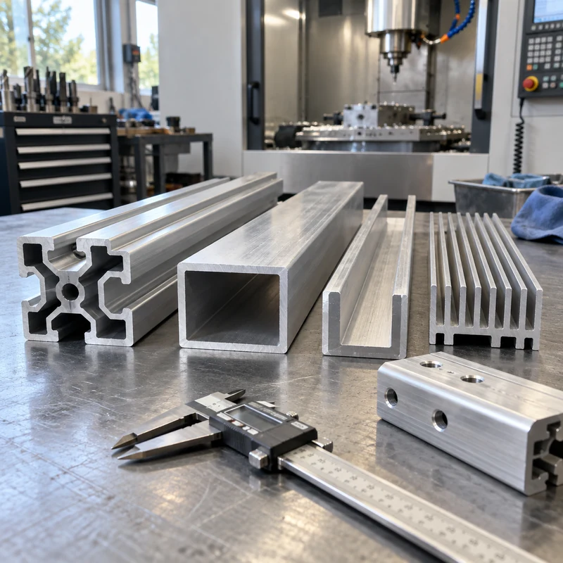
Section Useful function What to check before ordering
T-slot framing Adjustable brackets, guarding, and equipment frames Actual slot dimensions, nut engagement, compatible hardware, joint rigidity
Angle or open channel Edges, guides, supports, and simple brackets Loading direction, twisting, mounting access, exposed edges
Hollow tube Lightweight frames and protected internal space Wall thickness, internal access, joining method, drainage
Finned section Thermal-management components Fin spacing, airflow, base flatness, attachment to the heat source
Custom enclosure Integrated rails, cover interfaces, and mounting features Tooling cost, cover fit, machining stock, finish buildup

Extruders also classify sections as solid, hollow, or semi-hollow. Those classifications concern die geometry, including enclosed or partially enclosed spaces. A narrow opening can make an apparently simple shape difficult to produce. Ask the extruder to confirm the classification and feasibility rather than assigning it solely from appearance.

Use Stiffness and Joint Behavior to Select the Section

Two rails with similar outside dimensions can perform differently because the metal is distributed differently. For a simple beam under the same load and support conditions, bending deflection depends on elastic modulus and the section’s second moment of area. Turning a rectangular section through 90 degrees can therefore change deflection substantially.

For a machine frame, inspect the joints as carefully as the beams. A stiff rail attached through a slipping bracket may still allow poor positioning. Obtain the supplier’s section properties, model the real support conditions, and include the connection details. Do not select a larger rail merely because it looks more substantial.

Specify Alloy and Temper Together

6063 is commonly considered for complex profiles and appearance-sensitive applications; 6061 is often considered when strength and subsequent machining matter. Neither alloy name alone defines the finished performance. Temper, section thickness, manufacturing route, and any later thermal operations also matter.

Request the specified alloy and temper on the purchase order and material documentation. Where a design depends on a minimum mechanical property, use the applicable product specification rather than a generic internet value. Compare the requirements with your broader engineering material options before finalizing the drawing.

Keep Extrusion Tolerances Separate From Machined Tolerances

Profile dimensions, straightness, twist, cut length, and end squareness are separate requirements. A cross section that passes a dimensional check at one end can still cause assembly trouble over a long length. Establish the final assembly datums and identify which characteristics are controlled by extrusion and which require machining.

For example, an enclosure may accept ordinary extrusion variation on its outer walls while requiring an accurately machined connector opening. Dimension that opening from functional mounting datums, not from a decorative surface that varies between extrusion lots. This distinction makes the drawing easier to quote and inspect.

Design the Section for Secondary CNC Work

Relatively balanced walls and smooth transitions help the extrusion process. For downstream machining, also reserve accessible clamping areas and sufficient stock on precision faces. A thin lip may deform under a vise even though it was easy to extrude. Consider a supporting fixture or revised clamping location before increasing cutting pressure.

  • Place local features where drills and milling cutters can reach them.
  • Check that a tapped hole has enough engagement after finishing.
  • Allow an inspection probe or gauge to reach critical features.
  • Identify surfaces that must remain free of clamp marks.
  • Discuss the machining sequence when substantial material removal could release distortion.

The comparison of extrusion and CNC machining is useful when deciding whether to start from a profile or machine the entire part from stock.

Check Hardware Fit After Surface Treatment

A nominal frame series is not a complete hardware specification. Confirm the groove opening, internal seat, nut dimensions, screw length, and access for assembly. Parts from different systems can look compatible without sharing those details.

Specify whether fit requirements apply before or after coating. Anodizing or another finish can change functional clearances, and masked areas may be needed. Agree on visible-surface acceptance and sample approval with the surface finishing requirements, especially where adjacent components must match.

Compare Total Cost With a Simple Break-Even Model

Compare complete delivered components, including the die, material, cutting, machining, finishing, inspection, and scrap. A custom section can save downstream work, but those savings must repay the tooling and qualification effort.

Illustrative calculation, not a quotation: if custom tooling costs $2,400 and the resulting section saves $6 per finished component, the tooling-only break-even quantity is 400 components. Add qualification costs and any minimum-order inventory before making the purchase decision. Obtain both routes against the same drawing revision.

What to Include in an RFQ

Provide the cross-section drawing, finished length, quantity, alloy and temper, critical tolerances, finish, assembly interfaces, and expected annual demand. Separate raw-profile requirements from the finished-part drawing. Include a model for local machined features and clarify ownership of any custom die.

Frequently Asked Questions

Can extrusion create holes at specific positions along a rail?

Discrete cross holes and local pockets generally require secondary operations. Extrusion produces the continuous section; their locations must be defined on the finished-part drawing.

Is a custom profile always cheaper than a standard section?

No. It depends on tooling, order quantity, purchased material, and the operations it removes. A standard section can remain preferable for uncertain demand or frequent revisions.

Should every surface have a tight tolerance?

No. Apply tight controls to functional interfaces and justify them through the assembly. Unnecessary precision increases cost without necessarily improving performance.

Categories
Blog Design, Cost & Sourcing Guides

Image-to-3D Model Tools: How to Evaluate Mesh Quality for Manufacturing

Image-to-3D tools can reconstruct a mesh from one or more photographs in minutes. That speed is useful for visualization and concept exploration, but the output should not be confused with an engineering CAD model. A mesh can look convincing on screen while containing incorrect dimensions, broken surfaces, impossible internal geometry, or topology that fails during slicing and CAM preparation.

Instead of choosing software by render quality alone, manufacturers should evaluate view consistency, mesh validity, scale, editability, export formats, privacy, commercial rights, and the effort required to reach a controlled CAD model.

Quick Answer

Use image-to-3D generation for concept form, reference geometry, and fast visual models. Repair the mesh before printing, and rebuild critical products in parametric CAD before CNC machining, tooling, tolerance analysis, or production release.

Comparison at a Glance

Criterion Good result Manufacturing warning
Shape reconstruction Consistent form across all views Invented back-side or hidden features
Topology Closed manifold mesh with rational density Holes, self-intersections, floating shells
Scale Known reference dimension Arbitrary units or distorted proportions
Editability Local repair and controlled export One-click regeneration changes the whole model
Rights and privacy Clear commercial license and data policy Restricted use or confidential uploads retained

What a Single Image Cannot Tell the Model

A photograph does not reveal hidden faces, true depth, wall thickness, internal channels, thread geometry, material, or tolerance. The system estimates those details from learned visual patterns. A plausible estimate may be acceptable for a character or decorative asset, but it is not evidence of mechanical correctness.

Use several controlled views when the tool supports them. Keep focal length, lighting, and orientation consistent, and include a scale reference. Even then, verify all interfaces independently.

Mesh Quality Comes Before Visual Quality

Inspect the exported mesh rather than judging only the preview render. Common failures include non-manifold edges, inverted normals, intersecting surfaces, duplicate shells, holes, thin regions, irregular triangles, and unnecessary polygon counts.

A watertight mesh is necessary for many printing workflows, but watertight does not mean manufacturable. A repaired file can still have weak walls, inaccessible cavities, unrealistic clearances, or geometry that cannot be inspected.

  • Run manifold and self-intersection checks
  • Remove floating components
  • Confirm wall thickness and clearances
  • Reduce polygons without destroying edges
  • Test the final export, not only the cloud preview

Scale and Dimensional Control

Generated meshes often have no trustworthy units. Establish at least one known dimension, then measure several independent features to detect non-uniform distortion. Scaling the whole object cannot correct a housing whose width, height, and hole pattern were reconstructed at different proportions.

For reverse engineering, measured data from calipers, CMM, structured-light scanning, or drawings should control the final model. Photographs can support shape interpretation but should not replace measurement.

From AI Mesh to 3D Printing

Concept models can often be printed after mesh repair, orientation, hollowing, support design, and minimum-wall checks. Choose the print process based on what the model must prove: inexpensive FDM for size and handling, resin for visual detail, or nylon powder for functional geometry.

Print a reduced-risk test first when the model has thin sections or uncertain surfaces. Record any manual repairs so later regeneration does not silently remove them.

From AI Mesh to CNC-Ready CAD

CNC manufacturing needs explicit planes, cylinders, hole sizes, datums, corner radii, tool access, workholding surfaces, material, tolerances, threads, and finish notes. Triangle meshes do not naturally provide these controls.

Use the mesh as an underlay and rebuild critical geometry with sketches and parametric features. Direct mesh-to-solid conversion may work for simple low-density objects, but dense organic meshes often create heavy files and fragile surfaces that are difficult to revise.

  • Rebuild mating interfaces first
  • Create machinable internal radii
  • Define standard holes and threads
  • Add stock and fixture access
  • Export STEP and issue a controlled drawing

How to Compare Two Image-to-3D Platforms

Run the same input set through both tools and score the downloadable output. Do not rely on vendor showcase examples. Measure reconstruction consistency, hidden-side behavior, topology, texture quality, processing time, export access, edit controls, credit cost, and licensing.

A tool that produces a slightly less attractive preview but a cleaner, editable mesh may save more engineering time. For manufacturing, downstream repair effort matters more than the first render.

Security, Licensing, and Traceability

Before uploading customer products, drawings, or unreleased designs, review retention, training use, ownership, regional storage, deletion, and commercial licensing terms. Public AI services may not be suitable for controlled technical data.

Keep the source images, prompt, model version, exported mesh, repair history, and final CAD revision together. This creates traceability when the geometry changes or a license question arises.

Manufacturing Acceptance Checklist

The model is ready for quotation only when its purpose and remaining uncertainty are visible to the supplier.

  • Units and overall scale confirmed
  • Mesh validity checked
  • Critical dimensions rebuilt or documented
  • Material and process selected
  • Tolerances and datums identified
  • Threads and inserts specified
  • Commercial rights and confidentiality approved

Frequently Asked Questions

Can a single product photo create an accurate 3D model?

It can create an approximate visible form, but hidden geometry and depth are inferred. Accurate mechanical work needs multiple views plus measured dimensions or scan data.

Can an AI-generated mesh go directly to a CNC machine?

CAM may import some meshes, but reliable CNC production normally requires repaired surfaces or rebuilt CAD, defined tolerances, material, setup planning, and drawings.

Which export format is best?

OBJ, STL, or GLB are common for meshes and visualization. STEP is generally preferred for controlled mechanical CAD and CNC quotation after the geometry has been rebuilt.

Related MTSPi Resources

Request A Quote

We'll Send You Back with Price Immediately!

DEC 1-31

XMAS SPECEIL

Up to

40% off

Image-to-3D Model Tools: How to Evaluate Mesh Quality for Manufacturing

We'll Send You Back with Price Immediately!