Categories
Blog Design, Cost & Sourcing Guides

Image-to-3D Model Tools: How to Evaluate Mesh Quality for Manufacturing

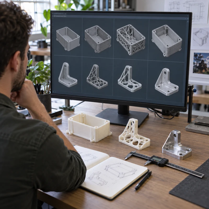
Image-to-3D tools can reconstruct a mesh from one or more photographs in minutes. That speed is useful for visualization and concept exploration, but the output should not be confused with an engineering CAD model. A mesh can look convincing on screen while containing incorrect dimensions, broken surfaces, impossible internal geometry, or topology that fails during slicing and CAM preparation.

Instead of choosing software by render quality alone, manufacturers should evaluate view consistency, mesh validity, scale, editability, export formats, privacy, commercial rights, and the effort required to reach a controlled CAD model.

Quick Answer

Use image-to-3D generation for concept form, reference geometry, and fast visual models. Repair the mesh before printing, and rebuild critical products in parametric CAD before CNC machining, tooling, tolerance analysis, or production release.

Comparison at a Glance

Criterion Good result Manufacturing warning
Shape reconstruction Consistent form across all views Invented back-side or hidden features
Topology Closed manifold mesh with rational density Holes, self-intersections, floating shells
Scale Known reference dimension Arbitrary units or distorted proportions
Editability Local repair and controlled export One-click regeneration changes the whole model
Rights and privacy Clear commercial license and data policy Restricted use or confidential uploads retained

What a Single Image Cannot Tell the Model

A photograph does not reveal hidden faces, true depth, wall thickness, internal channels, thread geometry, material, or tolerance. The system estimates those details from learned visual patterns. A plausible estimate may be acceptable for a character or decorative asset, but it is not evidence of mechanical correctness.

Use several controlled views when the tool supports them. Keep focal length, lighting, and orientation consistent, and include a scale reference. Even then, verify all interfaces independently.

Mesh Quality Comes Before Visual Quality

Inspect the exported mesh rather than judging only the preview render. Common failures include non-manifold edges, inverted normals, intersecting surfaces, duplicate shells, holes, thin regions, irregular triangles, and unnecessary polygon counts.

A watertight mesh is necessary for many printing workflows, but watertight does not mean manufacturable. A repaired file can still have weak walls, inaccessible cavities, unrealistic clearances, or geometry that cannot be inspected.

  • Run manifold and self-intersection checks
  • Remove floating components
  • Confirm wall thickness and clearances
  • Reduce polygons without destroying edges
  • Test the final export, not only the cloud preview

Scale and Dimensional Control

Generated meshes often have no trustworthy units. Establish at least one known dimension, then measure several independent features to detect non-uniform distortion. Scaling the whole object cannot correct a housing whose width, height, and hole pattern were reconstructed at different proportions.

For reverse engineering, measured data from calipers, CMM, structured-light scanning, or drawings should control the final model. Photographs can support shape interpretation but should not replace measurement.

From AI Mesh to 3D Printing

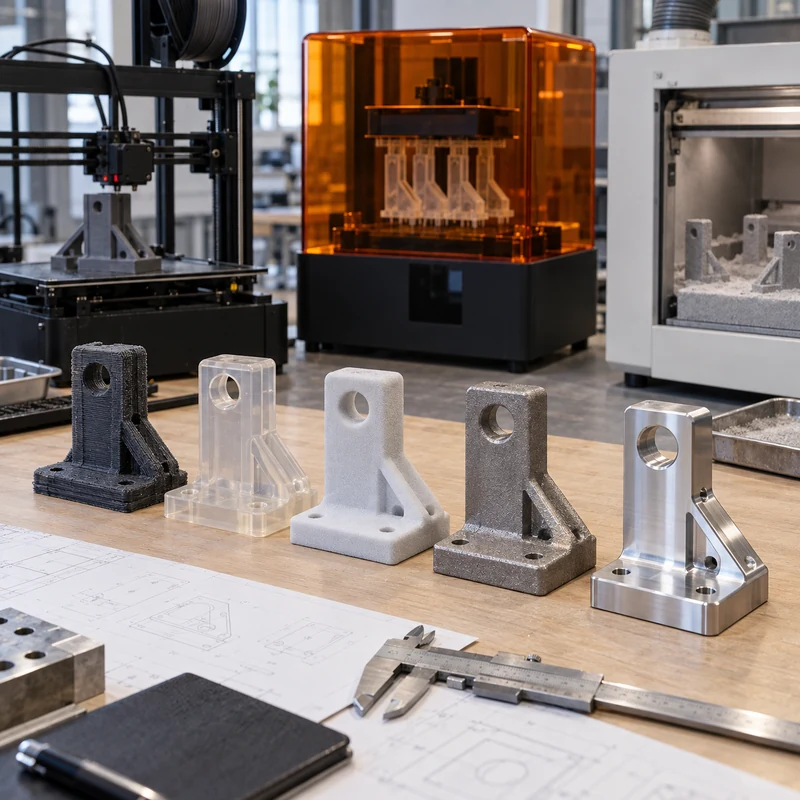
Concept models can often be printed after mesh repair, orientation, hollowing, support design, and minimum-wall checks. Choose the print process based on what the model must prove: inexpensive FDM for size and handling, resin for visual detail, or nylon powder for functional geometry.

Print a reduced-risk test first when the model has thin sections or uncertain surfaces. Record any manual repairs so later regeneration does not silently remove them.

From AI Mesh to CNC-Ready CAD

CNC manufacturing needs explicit planes, cylinders, hole sizes, datums, corner radii, tool access, workholding surfaces, material, tolerances, threads, and finish notes. Triangle meshes do not naturally provide these controls.

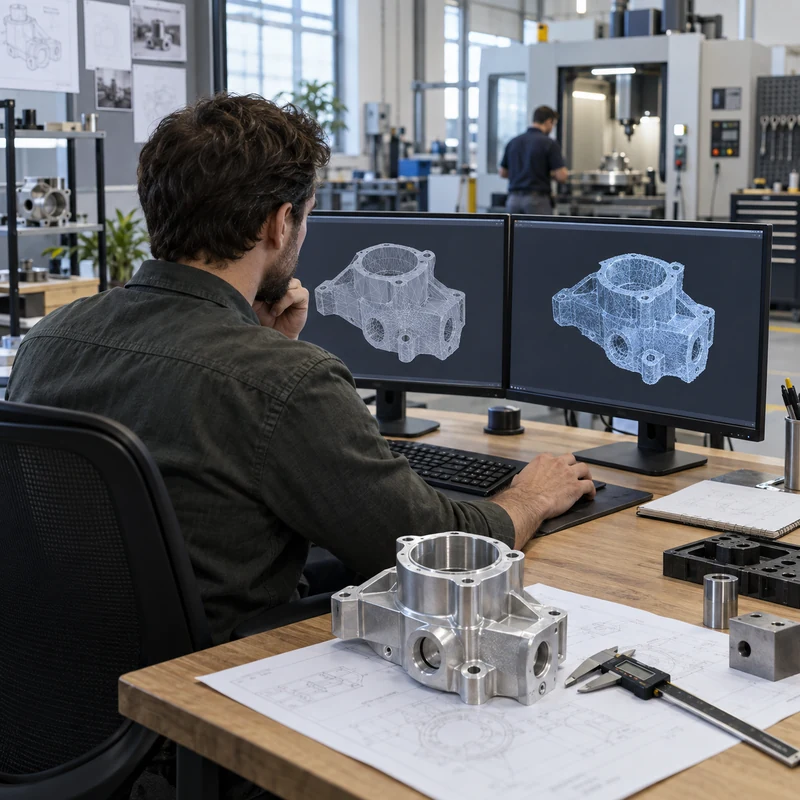
Use the mesh as an underlay and rebuild critical geometry with sketches and parametric features. Direct mesh-to-solid conversion may work for simple low-density objects, but dense organic meshes often create heavy files and fragile surfaces that are difficult to revise.

  • Rebuild mating interfaces first
  • Create machinable internal radii
  • Define standard holes and threads
  • Add stock and fixture access
  • Export STEP and issue a controlled drawing

How to Compare Two Image-to-3D Platforms

Run the same input set through both tools and score the downloadable output. Do not rely on vendor showcase examples. Measure reconstruction consistency, hidden-side behavior, topology, texture quality, processing time, export access, edit controls, credit cost, and licensing.

A tool that produces a slightly less attractive preview but a cleaner, editable mesh may save more engineering time. For manufacturing, downstream repair effort matters more than the first render.

Security, Licensing, and Traceability

Before uploading customer products, drawings, or unreleased designs, review retention, training use, ownership, regional storage, deletion, and commercial licensing terms. Public AI services may not be suitable for controlled technical data.

Keep the source images, prompt, model version, exported mesh, repair history, and final CAD revision together. This creates traceability when the geometry changes or a license question arises.

Manufacturing Acceptance Checklist

The model is ready for quotation only when its purpose and remaining uncertainty are visible to the supplier.

  • Units and overall scale confirmed
  • Mesh validity checked
  • Critical dimensions rebuilt or documented
  • Material and process selected
  • Tolerances and datums identified
  • Threads and inserts specified
  • Commercial rights and confidentiality approved

Frequently Asked Questions

Can a single product photo create an accurate 3D model?

It can create an approximate visible form, but hidden geometry and depth are inferred. Accurate mechanical work needs multiple views plus measured dimensions or scan data.

Can an AI-generated mesh go directly to a CNC machine?

CAM may import some meshes, but reliable CNC production normally requires repaired surfaces or rebuilt CAD, defined tolerances, material, setup planning, and drawings.

Which export format is best?

OBJ, STL, or GLB are common for meshes and visualization. STEP is generally preferred for controlled mechanical CAD and CNC quotation after the geometry has been rebuilt.
Related MTSPi Resources

Categories
Blog Guides Manufacturing Process Comparisons

Industrial 3D Printing Processes: A Requirement-Based Selection Guide

Industrial 3D printing is not one process. Resin vat systems, polymer powder-bed machines, metal powder fusion, filament extrusion, and pellet extrusion produce very different parts even when they start from the same CAD file. The best choice depends on the requirement that cannot be compromised.

A useful selection method filters processes in order: material, build size, feature detail, service conditions, geometry, surface requirements, and quantity. This prevents a visually attractive prototype from being mistaken for a production-capable part.

Quick Answer

Use SLA or DLP for fine visual detail, SLS or MJF for durable nylon geometry without support structures, FDM for economical engineering thermoplastics, FGF for very large parts, and metal powder-bed fusion for high-value metal geometry. Add CNC machining when datums, bores, sealing faces, or tight fits exceed as-printed capability.

Comparison at a Glance

Process family Typical material Best fit Key limitation
SLA / DLP Photopolymer resin Detailed visual and fit models Creep, UV aging, and brittle grades
SLS / MJF Nylon powder Functional parts and complex channels Grainy surface and moderate tolerance
Metal powder fusion Steel, aluminum, titanium, nickel alloy Load-bearing metal geometry Cost, supports, stress relief, finishing
FDM Filament thermoplastics Fixtures, housings, and heat-resistant prototypes Layer anisotropy and visible layer lines
FGF Pellet thermoplastics Large tools, patterns, and structures Coarse detail and machining allowance

1. Start With Material and Service Conditions

Ask whether the part must be metal, a production thermoplastic, an elastomer, transparent, sterilizable, chemically resistant, or stable at temperature. Material requirements remove unsuitable processes faster than comparing nominal resolution.

Resin can reproduce small details but usually does not behave like molded ABS or polycarbonate. Nylon powder processes offer better toughness for functional assemblies. FDM and FGF can use engineering thermoplastics, but orientation affects strength. Metal systems serve demanding thermal and mechanical duties, with post-build heat treatment often required.

  • Define sustained and peak temperature
  • List fluids, cleaners, and UV exposure
  • Separate cosmetic tests from structural tests
  • Identify flame, medical, or aerospace documentation needs

2. Check the Complete Build Envelope

A part must fit along all three machine axes, including supports and orientation. Splitting a large model introduces joints, alignment error, finishing labor, and weaker load paths.

Large-format extrusion is often more practical than joining many small prints. Conversely, a huge machine does not guarantee fine features: nozzle size, layer height, and thermal movement still control detail.

3. Separate Resolution From Tolerance

Layer height and pixel size describe the machine’s smallest increments, not guaranteed dimensional accuracy. Part size, orientation, shrinkage, thermal history, support strategy, and measurement method determine actual results.

For critical interfaces, print near-net geometry and machine the mating faces. This hybrid route is common for metal prints, large FGF tools, and nylon components that need precise bores or sealing surfaces.

  • Mark inspection datums on the drawing
  • Define general and critical tolerances separately
  • Add stock to faces that will be machined
  • Confirm fixture access before printing

4. Let Geometry Decide Support Strategy

Powder-bed nylon surrounds the part with loose powder, enabling internal passages and complex overhangs without attached supports. Resin, filament, pellet, and metal processes require deliberate support and removal access.

Hollow resin parts need drainage. Metal channels may trap powder or support material. Long flat walls can warp. Design reviews should address escape holes, minimum walls, unsupported spans, trapped volumes, and inspection access before the build starts.

5. Plan Surface Finish as an Operation

SLA and DLP can deliver smooth visual surfaces after support removal and light finishing. SLS and MJF have uniform powder texture. FDM and especially FGF retain layer lines. Metal powder fusion normally needs blasting plus machining on critical faces.

Polishing changes texture but cannot create a precision datum. Machining controls dimensions but may not reach every cosmetic surface. Specify appearance zones and functional zones separately so the quote includes the right operations.

6. Match the Process to Quantity and Design Maturity

Printing is valuable while CAD changes frequently because there is no hard tool to remake. Unit cost remains relatively linear, so tooling becomes attractive after geometry stabilizes and demand rises.

A practical development route may use resin for early appearance, nylon for functional testing, CNC machining for production-material validation, and vacuum casting or injection molding for repeated plastic parts.

A Seven-Step RFQ Checklist

A complete request reduces quotation uncertainty and prevents the supplier from choosing a process based only on file format.

  • Material or required properties
  • Overall dimensions and smallest features
  • Critical tolerances and datums
  • Loads, temperature, and chemical exposure
  • Internal channels and support-removal access
  • Surface finish and color
  • Prototype quantity and expected future volume

Frequently Asked Questions

Which industrial 3D printing process is most accurate?

SLA and DLP generally reproduce the finest small details, but accuracy depends on geometry and scale. Tight functional dimensions may still require secondary machining.

When should CNC machining replace 3D printing?

Use CNC machining when the part needs production-grade stock properties, precise datums, threads, sealing surfaces, predictable tolerances, or a finish that is difficult to achieve additively.

Can printed parts be used for production?

Yes, when the material, process control, inspection, traceability, and economics meet the application. Production suitability must be demonstrated rather than assumed.

Related MTSPi Resources

Categories
Blog Design, Cost & Sourcing Guides

AI 3D Model Generators: How to Evaluate Models Before Printing or CNC

AI 3D model generators can turn text or images into meshes quickly, making them useful for concept exploration, visualization, games, and early prototype forms. A downloadable mesh is not automatically a manufacturing-ready model.

Mechanical production requires consistent scale, watertight geometry, controlled surfaces, feature dimensions, tolerances, materials, assembly logic, and revision history. This guide shows how to evaluate generated output before spending money on printing or machining.

Quick Answer

Use AI-generated models as concept geometry. Repair and validate the mesh before 3D printing. Rebuild critical products in parametric CAD before CNC machining, tooling, or tolerance-controlled production.

Comparison at a Glance

Factor Option A Option B
Output Usually polygon mesh Production engineering prefers controlled CAD
Dimensions May be arbitrary or inconsistent Must be explicitly defined
Topology Can contain holes and self-intersections Needs watertight valid geometry
Revisions Prompt changes may alter everything CAD supports controlled feature changes
Manufacturing Good for concept prints after repair Not automatically CNC-ready

What to Test in a Tool

Compare prompt adherence, image-to-3D quality, symmetry, view consistency, mesh density, export formats, commercial rights, privacy, and the ability to edit selected regions. Free access limits can change, so verify current terms directly.

Mesh Quality Checklist

Inspect for non-manifold edges, inverted normals, intersecting shells, thin walls, floating geometry, excessive polygons, and open surfaces. Confirm scale before slicing.

  • Repair watertightness
  • Reduce unnecessary polygons carefully
  • Check minimum wall and clearance
  • Orient and add supports
  • Run a small test print

From Mesh to CAD

Automatic surface conversion can create heavy, fragile models. For functional products, use the generated mesh as a visual reference and rebuild sketches, planes, holes, datums, ribs, and interfaces as controlled features.

3D Printing Use

Concept meshes can work well for appearance models once repaired. Choose FDM for inexpensive form studies, SLA for smooth detail, and powder-bed nylon for functional geometry.

Why CNC Needs More

CNC needs exact surfaces, machinable features, tool access, corner radii, setups, material, tolerances, and drawings. A visually plausible mesh can contain geometry that cannot be held, reached, or inspected.

  • Create STEP geometry
  • Define datums and tolerances
  • Review tool access
  • Select production material
  • Add drawings for threads and finishes

Licensing and Confidentiality

Confirm whether generated assets may be used commercially and whether uploaded product images or CAD data are retained for model training. Do not upload confidential customer geometry without approved terms.

Frequently Asked Questions

Can an AI mesh be CNC machined directly?

Sometimes CAM can import meshes, but product-quality CNC work generally benefits from repaired surfaces or rebuilt CAD plus controlled drawings.

Are free AI 3D tools truly free?

Many use credits, limited exports, watermarks, non-commercial terms, or paid high-resolution output. Verify current conditions.

What file format is best?

STL or OBJ suits mesh workflows; STEP is preferred for controlled mechanical CAD and CNC quoting.

Related MTSPi Resources

Categories
Blog Design, Cost & Sourcing Guides Manufacturing Process Comparisons

3D Printing Prototype Cost Guide: Pricing Factors and Scale-Up Decisions

3D printing prototype cost can range from a small desktop build to an expensive certified metal component. Price is driven by process, material, bounding volume, build height, supports, machine time, nesting, post-processing, inspection, quantity, and failure risk.

A useful estimate begins with what the prototype must prove. A visual model, fit-check part, functional nylon component, transparent flow model, and metal load-bearing prototype should not use the same process or budget.

Quick Answer

Choose the least expensive process that answers the current design question. FDM often suits early form and fit, SLA suits detail and smooth appearance, SLS or MJF suits functional nylon, and metal powder-bed fusion suits valuable complex metal geometry. Use CNC when production material, tight tolerances, or machined surfaces are essential.

Key Engineering Factors

Factor Practical effect Control method
Part size Larger bounding volume consumes capacity Hollow noncritical volumes and split models carefully
Build height More layers increase machine time Orient around function, finish, and risk
Support Adds material and removal labor Place supports on noncritical surfaces
Material Engineering and metal feedstocks cost more Match material to the test purpose
Finishing Sanding, dyeing, machining, and coating add labor Specify only required surfaces

Cost by Prototype Purpose

Appearance models prioritize detail, color, and finish. Fit models prioritize dimensions and interfaces. Functional models add material behavior, load, temperature, and fatigue. Certification or end-use parts add traceability and inspection.

Process Cost Differences

FDM has low material and equipment cost but visible layers and directional strength. SLA provides fine detail but requires washing, curing, and support finishing. SLS and MJF nest parts in powder and suit functional batches. Metal printing adds powder control, supports, heat treatment, and machining.

Geometry That Raises Price

Tall builds, large solid volumes, extensive supports, trapped powder, thin fragile features, difficult cleaning, and tight tolerances raise cost. A complex-looking lattice may be economical if it prints support-free, while a simple tall wall may dominate build time.

  • Separate cosmetic and functional surfaces
  • Avoid unnecessary solid mass
  • Provide drain and powder-removal openings
  • Use realistic minimum walls and holes
  • Add stock for machined critical features

Quantity and Build Utilization

Unit cost can fall when multiple parts share setup and build capacity, especially in powder-bed systems. However, a larger batch also increases exposure if the design is unverified. Order a small validation lot before scaling.

Post-Processing and Inspection

Support removal, blasting, curing, dyeing, smoothing, painting, heat treatment, HIP, CNC finishing, threaded inserts, and CMM inspection can exceed the raw print cost. Quote them explicitly.

When to Move to CNC or Injection Molding

Move to CNC when the design needs production-intent stock, tight bores, flat sealing faces, threads, surface roughness, or predictable isotropic behavior. Consider molding when design and demand stabilize enough to recover tooling cost.

  • Use printing for fast learning
  • Use CNC for material and tolerance validation
  • Use bridge tooling for uncertain early demand
  • Calculate total lifetime cost before production tooling

RFQ Checklist

Send a STEP file, process or material preference, quantity, finish, color, critical tolerances, inspection level, and delivery requirement. Explain what the prototype must prove so the supplier can recommend alternatives.

Frequently Asked Questions

What is the cheapest 3D printing process?

FDM is often cheapest for simple early prototypes, but the best value depends on size, detail, quantity, material, and finishing.

Why is metal 3D printing expensive?

Metal systems require costly equipment, controlled powder, long builds, supports, heat treatment, safety procedures, inspection, and frequent CNC post-processing.

Is 3D printing always cheaper than CNC machining?

No. CNC can be more economical for simple geometry, production material, precise features, and small batches where printed post-processing is extensive.

Related MTSPi CNC Resources

Categories
Blog Design, Cost & Sourcing Guides Industries & Applications

Rigid-Flex PCB Design Guide: Stackup, Bend Rules, Enclosures, and Assembly

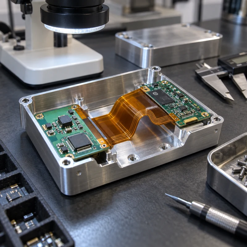
A rigid-flex PCB combines rigid circuit sections with flexible polyimide interconnects in one laminated assembly. It can replace connectors and wire harnesses, save space, reduce assembly steps, and support controlled three-dimensional packaging.

The advantages come with stricter mechanical rules. Bend radius, copper direction, coverlay, layer transitions, stiffeners, enclosure clearances, and assembly sequence must be coordinated early.

Quick Answer

Use rigid-flex when packaging, reliability, weight, or connector reduction justifies the added design and fabrication complexity. Keep bends away from rigid transitions, vias, solder joints, and sharp enclosure edges. Validate the folded state with production-intent stackup and housing geometry.

Key Engineering Factors

Factor Practical effect Control method
Bend radius Too small a radius strains copper and dielectric Set radius from stackup and flex type
Rigid-flex transition Stress concentrates at the boundary Use controlled transition and strain relief
Copper layout Traces across bend can fatigue Route perpendicular to bend and stagger layers
Enclosure clearance Pinching or rubbing damages flex Model dynamic and assembled envelopes
Assembly sequence Fold order can load components Document fixtures and installation steps

How Rigid-Flex Construction Works

Rigid sections commonly use FR4 while flexible sections use polyimide and rolled or electrodeposited copper. Coverlay protects flex conductors. Adhesives, no-flow prepreg, stiffeners, and plated features are selected around stackup and reliability.

Static vs Dynamic Flexing

A static flex bends during assembly and then remains in position. A dynamic flex moves repeatedly in service and needs larger radii, suitable copper, balanced layers, controlled neutral axis, and fatigue validation.

Bend-Area Design Rules

Keep pads, vias, component terminations, abrupt width changes, and rigid edges away from active bends. Curved trace transitions and staggered conductors reduce stress concentration.

  • Route traces perpendicular to bend axis
  • Avoid copper corners and teardrop discontinuities in flex zones
  • Use hatched planes when solid copper makes the section too stiff
  • Define bend direction and final folded angle
  • Confirm minimum radius with the fabricator

Mechanical Enclosure Integration

The housing must support rigid boards while allowing the flex to follow a natural curve. Avoid sharp machined edges, screw interference, compression, and excessive free length. Include assembly access and serviceability.

  • Import the PCB STEP model into enclosure CAD
  • Model the flex in its assembled state
  • Add edge radii and protective clearances
  • Support heavy connectors on rigid sections
  • Check thermal and EMI contact intentionally

Stackup and Fabrication Communication

Provide the controlled stackup, impedance needs, copper weights, materials, surface finish, stiffeners, coverlay openings, controlled-depth features, and test requirements. Ask the fabricator to review the design before layout release.

Assembly and Inspection

Rigid-flex assemblies may require dedicated carriers, fold fixtures, and handling instructions. Inspect conductor continuity, finished outline, plating, coverlay registration, impedance, solder quality, and the final folded assembly.

CNC-Machined Housing Considerations

CNC housings provide strong mounting, shielding, sealing, and thermal paths. Tolerance stacks must include board outline, connector position, standoff height, coating, gasket compression, and flex clearance.

Frequently Asked Questions

How many times can a rigid-flex PCB bend?

Static designs may only bend during assembly; dynamic life depends on stackup, radius, copper, stroke, environment, and testing.

Can vias be placed in the bend area?

They should generally be kept outside active bends because plated holes create stiffness and stress concentration.

Why use rigid-flex instead of cables?

It can reduce connectors, assembly labor, space, weight, and potential connection failures when the program justifies the higher fabrication complexity.

Related MTSPi CNC Resources

Categories
Blog CNC Materials Guides Manufacturing Process Comparisons

PVC Extrusion Guide: Process, Materials, Design Rules, and Quality Control

PVC extrusion produces continuous rigid and flexible profiles for construction, equipment, electrical, fluid-handling, sealing, and industrial applications. PVC is versatile and cost-effective, but it is thermally sensitive and requires controlled compounding and processing.

This guide explains the full route from compound and die to cooling, haul-off, cutting, inspection, and secondary machining.

Quick Answer

Rigid PVC suits structural profiles, channels, pipe, and housings. Flexible PVC suits seals, sleeves, and cable-related products. Stable results require correct formulation, gentle heat history, balanced die flow, controlled cooling, and inspection after conditioning.

Key Engineering Factors

Factor Practical effect Control method
Compound Stabilizers, impact modifiers, pigments, and fillers change behavior Lock the approved formulation
Heat history Excess temperature can degrade PVC Control barrel, die, screw, and residence time
Profile balance Uneven sections distort during cooling Use balanced walls and calibrated surfaces
Cooling Controls final size and residual stress Maintain consistent vacuum and water conditions
Weathering UV and environment change service life Specify outdoor grade and color requirements

Rigid PVC vs Flexible PVC

Rigid PVC has higher stiffness and is common in profiles, pipe, conduit, and frames. Flexible PVC contains plasticizers and is used for seals, tubing, sleeves, and protective components. Their tooling, shrinkage, hardness, and testing requirements differ.

PVC Extrusion Process

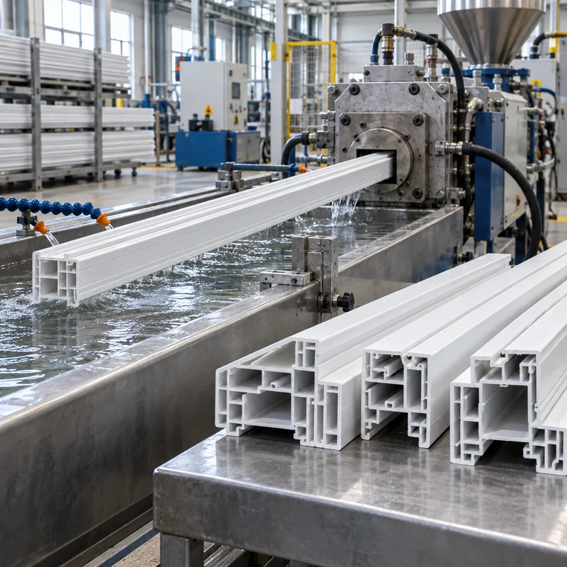
Dry blend or pellets feed the extruder, where the screw conveys, heats, mixes, and pressurizes the compound. The die shapes the melt. Calibration and cooling stabilize it, the haul-off controls speed, and a saw or cutter creates final lengths.

Profile Design Rules

Uniform walls and gradual transitions improve flow. Multi-chamber profiles need webs that remain stable through calibration. Sharp corners, isolated thick masses, and fragile fins increase tooling and process risk.

  • Use radii at internal transitions
  • Balance opposite walls where possible
  • Allow room for calibration tooling
  • Define visible surfaces and texture
  • Identify mating and sealing dimensions

Common PVC Extrusion Defects

Burn marks can indicate degradation or stagnation. Wavy surfaces may reflect unstable output or pull. Bow and twist arise from unbalanced cooling. Die lines, poor gloss, bubbles, and dimensional drift each require process-specific diagnosis.

  • Do not solve every defect by changing line speed
  • Check compound moisture and contamination
  • Inspect die buildup and flow restrictions
  • Confirm cooling and puller alignment

Quality and Testing

Dimensional inspection should include cross-section, wall thickness, bow, twist, cut length, and fit with mating parts. Depending on service, test impact, hardness, color, gloss, weathering, flammability, chemical resistance, or low-temperature behavior.

Secondary Fabrication and CNC Work

PVC profiles can be drilled, routed, milled, punched, welded, bonded, printed, and assembled. Cutting heat and clamping pressure must be controlled to prevent melting, cracking, or deformation.

Sourcing Checklist

Provide a controlled cross-section drawing, CAD data, compound specification, color, surface requirements, expected volume, packaging, cut length, environmental exposure, and test standards. Approve conditioned samples before final tooling release.

Frequently Asked Questions

Does PVC need drying before extrusion?

Requirements depend on the compound and storage. Moisture and contamination should still be controlled even when drying is less demanding than for hygroscopic polymers.

Can recycled PVC be used?

It can be used in suitable products, but formulation consistency, contamination, color, and mechanical requirements must be controlled.

Why does PVC turn yellow or brown?

Discoloration often indicates excessive heat, residence time, shear, or inadequate thermal stabilization.

Related MTSPi CNC Resources

Categories
Blog Design, Cost & Sourcing Guides

AI Product Rendering Tools for Designers: A Practical 2026 Workflow

AI product rendering tools can turn a sketch, text prompt, or rough model into polished visual concepts in minutes. They are valuable for exploring proportion, finish, color, context, and presentation, but a convincing image is not automatically manufacturable geometry.

For mechanical products, the strongest workflow keeps visualization, CAD, engineering analysis, DFM, and physical prototyping as separate but connected stages. This guide explains how designers can use AI images without allowing visual plausibility to replace dimensional truth.

Quick Answer

Use AI rendering for rapid visual exploration and communication. Use parametric CAD for dimensions, interfaces, tolerances, and revision control. Validate important decisions through DFM review and a CNC-machined or printed prototype before production.

Key Differences at a Glance

Factor Option A Option B Engineering note
Primary output Visual concept CAD or physical prototype Do not quote from an image alone
Speed Seconds to minutes Hours to days Use AI early when change is cheap
Dimensional accuracy Not dependable Controlled Critical interfaces require CAD
Material behavior Appearance simulation Engineering data and tests A metallic look does not prove alloy performance
Best use Style, context, presentation Fit, function, manufacturing Combine the two workflows

Where AI Rendering Adds Real Value

AI makes it inexpensive to explore many visual directions before a team commits to detailed CAD. It can test enclosure language, color families, surface finishes, product context, and presentation for stakeholder review.

  • Generate several distinct design directions
  • Keep prompts tied to user and environment
  • Separate cosmetic intent from engineering constraints
  • Record which visual decisions are approved

Where AI Images Become Risky

Generated images may invent fasteners, impossible parting lines, non-uniform wall thickness, inaccessible undercuts, floating internal components, and inconsistent geometry between views. A beautiful render can hide assembly and thermal problems.

  • Never derive final dimensions from pixels
  • Do not assume repeated views represent one consistent model
  • Check vents, seals, connectors, screw bosses, and tool access
  • Treat generated mechanisms as concepts until engineered

A Seven-Step Product Workflow

Begin with a concise requirement brief, generate visual concepts, select a direction, rebuild it in controlled CAD, perform DFM review, produce a prototype, and update both CAD and presentation assets after testing. This keeps visual speed while preserving engineering discipline.

  • Define user, function, environment, and manufacturing volume
  • Generate mood and form alternatives
  • Create production-intent CAD
  • Review tolerances and process constraints
  • Prototype critical interfaces
  • Test assembly and appearance
  • Freeze controlled revision data

Connecting Renders to CNC Manufacturing

For machined products, CAD must define stock access, tool reach, corner radii, wall thickness, thread engagement, tolerances, surface finish, and coating allowance. The render can communicate appearance, while STEP files and drawings control manufacturing.

  • Use realistic internal corner radii
  • Avoid deep narrow pockets without function
  • Specify bead blast, brushing, anodizing, or plating separately
  • Provide 2D drawings for critical dimensions and finishes

How to Evaluate an AI Rendering Tool

The best tool depends on input type, view consistency, editing control, privacy, export options, and team workflow. Product teams should test a small controlled project rather than selecting from promotional images.

  • Can it preserve the same product across views?
  • Can selected areas be edited without changing everything?
  • Can it use sketches or CAD screenshots as guidance?
  • Are commercial use and data terms suitable?
  • Can output fit the review and approval workflow?

SEO and GEO Content Integrity

AI images should not be presented as photographs of factory capability or delivered customer parts. Label conceptual renders when necessary, use accurate alt text, and support technical claims with real engineering information. Trust depends on a clear boundary between visualization and evidence.

Frequently Asked Questions

Can an AI render be converted directly into a CNC program?

No. CNC programming needs valid 3D geometry, material, tolerances, setups, and toolpaths. A render is a visual reference, not a manufacturing model.

Can AI replace industrial designers?

It accelerates exploration, but designers still define requirements, judge concepts, resolve details, and coordinate engineering and production.

What files should be sent for a CNC quote?

Send STEP or STP geometry plus a 2D drawing for tolerances, threads, finishes, and inspection notes. Reference images can clarify appearance but should not control dimensions.

Related MTSPi CNC Resources

Categories
Blog CNC Materials Guides Manufacturing Process Comparisons

MJF vs SLS: Choosing the Right Nylon 3D Printing Process for Functional Parts

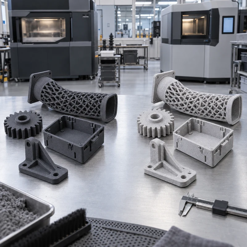
MJF and SLS both build nylon parts inside a powder bed without conventional support structures. That makes both processes useful for complex ducts, housings, clips, brackets, living hinges, lattice features, and low-volume assemblies. The practical differences appear in heat delivery, surface character, dimensional behavior, color, nesting strategy, and supplier workflow.

This MJF vs SLS guide explains those differences for engineers who need functional parts, not just visual models.

Quick Answer

Choose MJF when you want consistent mechanical behavior, fine detail, relatively uniform surfaces, and efficient batches of PA12 parts, especially when dark gray or dyed black is acceptable. Choose SLS when you need broad material availability, flexible build sizes, proven nylon options, or a supplier ecosystem suited to varied quantities and geometries. Test the actual material and orientation when fatigue, snap fits, pressure, or heat matters.

How MJF and SLS Work

SLS scans a laser across each powder layer and sinters the selected cross-section. MJF deposits fusing and detailing agents across the layer, then applies thermal energy. In both methods, surrounding powder supports the part, allowing nested builds and complex shapes without the support marks associated with many resin or filament processes.

MJF vs SLS Comparison

Factor MJF SLS
Energy delivery Fusing agents plus thermal energy Laser scans each cross-section
Typical appearance Graphite gray, often dyed black Natural white or light gray, easily dyed
Surface Fine, relatively uniform powder texture Slightly grainier texture depending on machine
Materials Strong focus on PA12 and selected polymers Broad nylon and specialty-powder ecosystem
Mechanical consistency Often relatively uniform in common PA12 builds Good but orientation and machine still matter
Supports Not normally required Not normally required
Best fit Functional batches and detailed PA12 parts Flexible materials, sizes, and established applications

Material Options

PA12 is the most common comparison material because it balances toughness, stiffness, chemical resistance, and dimensional stability. PA11 offers greater ductility for impact and snap features. Glass-filled nylons increase stiffness but can become less forgiving and more abrasive. TPU-like powders support flexible components, though machine availability and tolerances differ.

Always compare datasheets for the exact machine-material combination. A generic label such as “nylon” is not enough for a load-bearing design.

Accuracy and Dimensional Control

Both processes are suitable for functional prototypes, but neither should be treated like precision CNC machining. Large flat surfaces can warp, thin walls can move, and holes may print undersize. Geometry, orientation, cooling, packing density, and refresh ratio affect results.

  • Add clearance to mating printed parts instead of using nominal CAD fits.
  • Avoid very large unsupported flat panels; use ribs or gentle curvature.
  • Use consistent wall thickness and gradual transitions.
  • Machine or ream critical bores after printing when required.
  • Validate snap fits using the intended material, finish, and orientation.

Surface Finish, Color, and Sealing

Both processes leave a matte powder texture. Bead blasting creates a more uniform appearance. Dyeing is common, especially black. Tumbling or chemical smoothing can improve feel and cleanability but may soften small edges or change dimensions. Unsealed nylon remains somewhat porous, so pressure, fluid, and hygiene applications may need infiltration, coating, or a different process.

Strength and Functional Testing

Printed PA12 can support clips, ducts, covers, fixtures, and many load-bearing prototypes. However, long-term creep, fatigue, temperature, moisture, and chemicals should be considered. Use application loads rather than a single tensile value. Test thin hinges, snap arms, screw bosses, and press fits because these features concentrate strain.

Cost and Lead-Time Drivers

Driver Why it matters
Bounding box Controls how efficiently parts nest in the build
Build height Adds layers and machine time
Part quantity Dense nesting can lower unit cost
Powder refresh Material handling affects operating cost
Cooling Parts may remain in the build for controlled cooling
Finishing Blasting, dyeing, smoothing, and sealing add steps
Inspection Critical dimensions and lot records add labor

Design Recommendations

  • Use ribs and radii to support thin functional structures.
  • Keep escape openings large enough to remove powder from channels.
  • Do not create trapped cavities unless powder retention is acceptable.
  • Use threaded inserts for repeated assembly rather than relying on printed threads.
  • Separate cosmetic and critical dimensional surfaces on the drawing.
  • Mark surfaces that will be machined and provide stock where needed.

When CNC Machining Is the Better Choice

CNC machining is often better when the part needs a specific engineering plastic grade, tight hole or datum tolerances, low surface roughness, transparent material, stable flatness, or traceable stock properties. Printed nylon is excellent for geometry and low-volume function; machined nylon, POM, PEEK, aluminum, or other production materials may be better for final validation.

A Practical Selection Checklist

  • What exact polymer grade is required?
  • Which dimensions control assembly?
  • Will the part see fatigue, heat, moisture, pressure, or chemicals?
  • Does color or surface feel matter?
  • Can all trapped powder be removed?
  • Is the quantity high enough to benefit from dense nesting?
  • Should critical features be CNC finished?

Frequently Asked Questions

Is MJF stronger than SLS?

There is no universal answer. With comparable PA12, MJF often provides consistent properties, but machine settings, orientation, geometry, and finishing matter. Use supplier data and functional testing for critical parts.

Which process gives a smoother surface?

MJF often appears finer and more uniform, while SLS can feel slightly grainier. Both remain matte and benefit from blasting, dyeing, or smoothing when appearance matters.

Can MJF or SLS parts be CNC machined?

Yes. Printed parts can be drilled, tapped, reamed, milled, or fitted with inserts, provided the fixture supports the part and the design includes enough material around the feature.

Related MTSPi CNC Resources

Categories
Blog CNC Materials Guides Manufacturing Process Comparisons

Metal 3D Printing Guide: Processes, Materials, Applications, and CNC Post-Processing

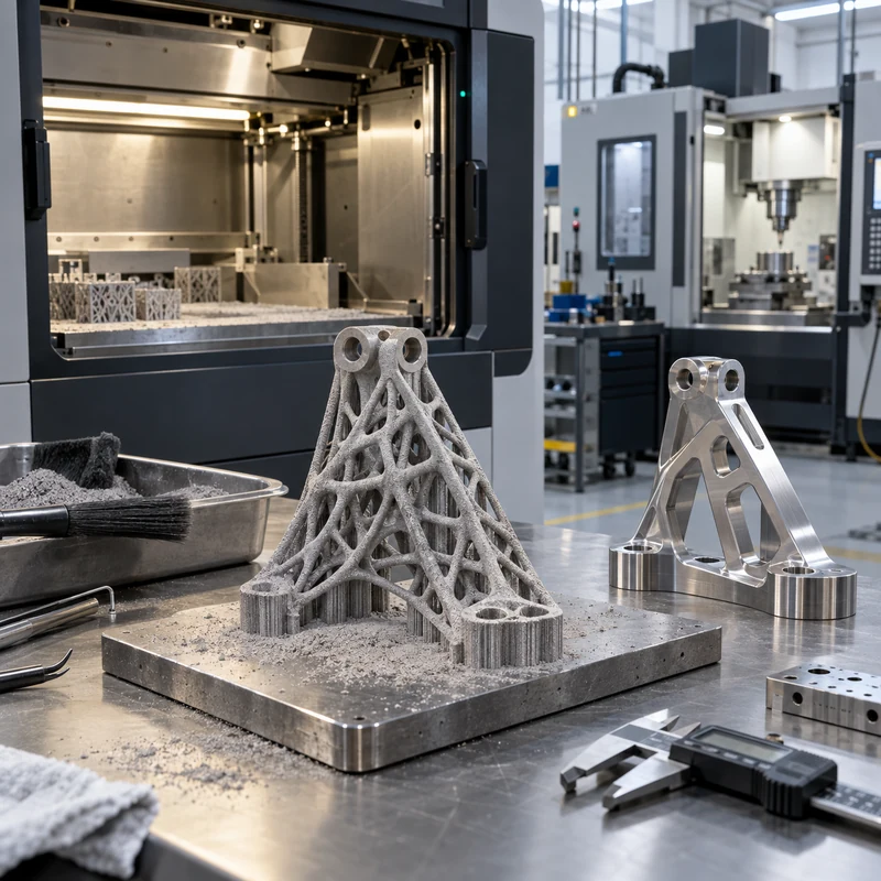
Metal 3D printing creates shapes that are difficult or impossible to machine from solid stock, including internal channels, lattice structures, consolidated assemblies, and topology-optimized parts. It is not a universal replacement for CNC machining. Printed parts commonly require support removal, heat treatment, surface finishing, dimensional inspection, and machining of critical features.

This guide compares the main metal additive processes and explains how to plan a complete production route rather than judging only the printing step.

Metal 3D Printing at a Glance

Process How it works Strength Typical fit
SLM/DMLS Laser fuses metal powder in a bed High after correct processing Complex precision parts and low volumes
EBM Electron beam melts powder in vacuum High Titanium and high-temperature applications
Binder jetting Binder shapes powder before sintering Process-dependent Higher throughput and smaller parts
DED Powder or wire is fed into an energy source High with controlled parameters Repair, cladding, and large near-net shapes

SLM and DMLS

Powder-bed fusion spreads a thin metal powder layer and selectively fuses each cross-section. The method supports complex geometry and fine features, but build orientation, supports, residual stress, powder removal, and scan strategy all affect the result. The terms SLM and DMLS are often used commercially for closely related laser powder-bed processes; the exact machine, material specification, and qualification route matter more than the label.

Electron Beam Melting

EBM uses an electron beam in a vacuum and maintains an elevated build temperature. It is strongly associated with titanium applications. The process can reduce some residual-stress concerns, but surfaces are generally rougher and dimensional finishing may still be required.

Binder Jetting

Binder jetting forms a fragile green part that is later debound and sintered. It can deliver higher throughput because the printhead works across the bed, but sintering shrinkage must be predicted and controlled. Density, distortion, feature size, and material-property requirements determine whether it is appropriate.

Directed Energy Deposition

DED feeds powder or wire into a melt pool. It is useful for adding material to existing components, repairing expensive parts, applying wear-resistant material, and producing large near-net preforms. Resolution is lower than powder-bed fusion, so machining is usually part of the route.

Common Metal Materials

Material Why it is printed Typical post-processing concern
316L stainless steel Corrosion resistance and broad usability Support removal and sealing surfaces
17-4PH stainless steel Strength after heat treatment Heat-treatment condition and final dimensions
AlSi10Mg aluminum Low mass and good printability Porosity, heat treatment, threaded features
Ti-6Al-4V High strength-to-weight ratio Oxygen control, fatigue surface, cost
Inconel alloys High-temperature performance Machining difficulty and residual stress
Cobalt chrome Wear and biomedical applications Qualification and finishing

Design Rules for Printable Metal Parts

  • Use additive geometry only where it creates measurable value.
  • Orient critical surfaces to balance supports, distortion, finish, and build time.
  • Provide escape paths for trapped powder in internal channels.
  • Add machining stock to bores, datums, threads, gasket faces, and bearing seats.
  • Avoid unsupported down-facing surfaces that create roughness or collapse risk.
  • Use gradual transitions to reduce local heat accumulation.
  • Design reference features that can be located during CNC finishing and inspection.

Accuracy, Surface Finish, and Porosity

As-printed accuracy is affected by machine calibration, thermal distortion, orientation, feature size, support strategy, and material. Surface texture varies by upward, vertical, and downward-facing orientation. Internal porosity and lack-of-fusion defects require process control and may require CT scanning or destructive validation for high-consequence parts.

Do not assign CNC-level tolerances to every printed surface. Separate additive surfaces from features that will be machined. This creates a realistic drawing and prevents unnecessary cost.

Why CNC Post-Processing Matters

CNC machining provides repeatable datums and functional interfaces after printing. A typical sequence can include stress relief, separation from the build plate, support removal, rough inspection, heat treatment or hot isostatic pressing, fixture preparation, CNC finishing, deburring, surface treatment, and final inspection.

The fixture plan must account for irregular printed surfaces. Purpose-designed sacrificial pads, cylinders, or tabs can give the machining setup reliable locating and clamping features, then be removed in a later operation.

Cost Drivers

  • Build volume and height, not just part weight.
  • Support material and support-removal labor.
  • Machine occupancy and number of parts nested in a build.
  • Powder type, reuse rules, and traceability.
  • Heat treatment, HIP, testing, and certification.
  • CNC setups, custom fixtures, and inspection.
  • Failed-build risk and qualification samples.

When to Choose Metal Printing, CNC, or a Hybrid Route

Choose metal printing for valuable geometric complexity, internal flow paths, mass reduction, consolidation, or very low-volume shapes. Choose CNC machining for prismatic or rotational parts, predictable tolerances, smooth surfaces, standard materials, and straightforward low-volume production. Use a hybrid route when the printed geometry creates value but interfaces still require precision.

Frequently Asked Questions

Are metal 3D printed parts fully dense?

Qualified powder-bed processes can achieve very high density, but density alone does not prove fatigue performance or absence of critical defects. Process qualification and application-specific testing remain important.

Can threads be printed directly?

Large non-critical threads may be printable, but tapped or CNC-machined threads are generally more predictable for assembly, gauges, sealing, and repeated use.

What should be included on the drawing?

Identify the additive process and material specification, post-processing condition, machined surfaces, datums, critical tolerances, inspection method, surface finish, and any qualification requirements.

Related MTSPi CNC Resources

Categories
Blog Guides Manufacturing Process Comparisons

SLA vs DLP Resin 3D Printing: Accuracy, Surface Finish, and Prototype Selection

SLA vs DLP Resin 3D Printing: Accuracy, Surface Finish, and Prototype Selection is a practical manufacturing question because the answer affects cost, lead time, material behavior, inspection, and the path from prototype to production. For MTSPi CNC customers, the key is not simply naming a process, but understanding how the process connects with machined parts, fixtures, tolerances, surface requirements, and final assembly.

This guide explains SLA vs DLP from an engineering and purchasing point of view. It is written for product developers, mechanical engineers, sourcing teams, and buyers who need clear decisions rather than generic process descriptions.

Quick Answer

Choose SLA or DLP based on part size, detail, surface finish, resin choice, and throughput. For final functional validation, compare printed resin limitations with CNC machined plastics or metals before approving the design.

Key Differences at a Glance

Point Option A Option B
Light method Laser traces each layer Projected image cures a layer
Speed Depends on scan length and geometry Often fast for full-layer exposure
Detail Very fine details possible Pixel size affects edge detail
Surface Smooth resin finish Smooth, sometimes pixel-related texture
Best use High-detail prototypes and appearance models Fast resin prototypes and small batches

How the Process Choice Affects Real Parts

A manufacturing method should be selected around the feature that actually controls function. Cosmetic surfaces, hidden support features, threads, bores, sealing faces, heat-transfer areas, and assembly datums do not carry the same risk. When those requirements are mixed together without priority, quotes become inconsistent and production becomes harder to control.

The safest workflow is to define the part requirement first, then match the process. A printed prototype may answer shape questions, a molded sample may answer appearance questions, and a CNC machined sample may answer tolerance, material, and functional questions. Many successful projects use more than one method before the final design is locked.

Design and Manufacturing Considerations

  • Use resin printing for appearance, fine detail, and early fit review.
  • Avoid assuming printed resin equals production ABS, nylon, aluminum, or steel.
  • Plan supports on non-critical surfaces when appearance matters.
  • Check thin walls and small pins against the printer and resin capability.
  • Use CNC machining for final material and tolerance validation.

Cost, Lead Time, and Risk Factors

Cost is driven by setup, tooling, material, machine time, inspection, finishing, and revision risk. A low unit price is not always the lowest project cost if it creates rework later. For prototypes and low-volume orders, flexibility can be more valuable than a process with a lower theoretical unit cost.

  • Use standard materials and standard feature sizes when they do not weaken the design.
  • Separate critical tolerances from general dimensions so the supplier knows where to focus.
  • Confirm surface finish and cosmetic requirements before production begins.
  • Avoid late changes to mounting holes, connector openings, datum faces, and threaded features.
  • Send CAD files and 2D drawings together when tolerances, threads, or finishes matter.

Quality Checks Before Production

A good quality plan checks the features that influence assembly and performance. Depending on the part, this may include dimensional inspection, thread gauges, surface roughness, flatness, perpendicularity, burr control, coating thickness, visual appearance, and fit with mating parts.

When This Topic Matters for CNC Buyers

SLA vs DLP matters when a team is comparing prototype routes, validating a design, replacing a weak supplier, or trying to reduce manufacturing cost without damaging function. The best choice is usually the process that answers the current engineering question with the least unnecessary risk.

MTSPi CNC Engineering Notes

MTSPi CNC supports precision CNC milling, turning, rapid prototyping, low-volume production, finishing, and inspection for custom parts. If your project uses molding, casting, welding, PCB assemblies, or 3D printing, CNC machining can still be important for datums, holes, threads, sealing faces, fixtures, and production-ready prototypes.

Frequently Asked Questions

Can this process replace CNC machining?

Sometimes it can replace CNC for non-critical geometry, but CNC is often still needed when tight tolerances, real engineering material, threads, flat sealing faces, or precise mating features are required.

What files help MTSPi CNC review a project?

STEP or STP files are useful for geometry. A 2D drawing is important for tolerances, materials, threads, surface finish, inspection requirements, and notes that are not obvious from the CAD model.

How do I reduce manufacturing risk?

Define critical features, avoid unnecessary tight tolerances, confirm material and finish requirements, and use prototypes to validate assembly before committing to higher-volume tooling or production.

Related MTSPi Resources

Request A Quote

We'll Send You Back with Price Immediately!

DEC 1-31

XMAS SPECEIL

Up to

40% off

SLA vs DLP Resin 3D Printing: Accuracy, Surface Finish, and Prototype Selection

We'll Send You Back with Price Immediately!