

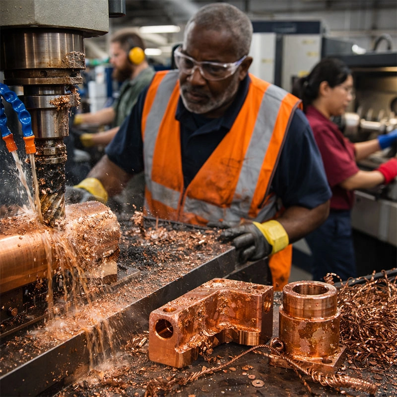
Working with copper on a CNC machine can be tricky. While it’s a fantastic material, its unique properties often lead to specific machining challenges. This guide walks you through the most frequent issues, like tool wear and surface finish problems, and offers practical, friendly advice on how to solve them for smoother, more efficient production runs.
Excessive Tool Wear and Breakage
If you’ve ever felt like you’re going through end mills faster than usual when milling copper, you’re not alone. Copper’s high ductility and softness mean it doesn’t always break away cleanly. Instead, it can sort of “smear” and create a lot of friction and heat against the cutting tool’s edge. This friction is the main culprit behind rapid tool degradation in copper CNC operations. You might notice the flutes of your tool getting worn down quickly, or worse, experiencing sudden tool failure mid-cut.
Choosing the Right Tools and Parameters
The fix here is a two-part strategy: tool selection and machine settings. First, let’s talk tools. For machining pure copper or high-copper alloys, we highly recommend using sharp, polished tools. Uncoated carbide end mills with a high positive rake angle are often a great choice because they slice through the material more easily, reducing cutting forces. Some machinists swear by diamond-coated tools for long production runs, as copper doesn’t react chemically with diamond. You can read more about advanced tool materials on Modern Machine Shop.
Next, dial in your parameters. Running at too high a surface speed can generate excessive heat, accelerating wear. Conversely, too slow a feed rate lets the tool rub instead of cut. Finding that sweet spot with a higher feed per tooth and a moderate spindle speed is key. It encourages a cleaner shear and helps the tool last longer. Think of it like slicing a soft tomato with a dull knife versus a sharp one—the right tool and a confident motion make all the difference.
Poor Surface Finish and Built-Up Edge
Nothing is more frustrating than a part that looks streaky, rough, or has tiny bits of material welded to its surface. This is a classic sign of built-up edge (BUE), a major headache in copper machining. When the heat and pressure get too high, tiny particles of the workpiece material can actually weld themselves to the cutting edge of your tool. This lump then acts as a poor, irregular cutting surface, scratching and tearing the copper instead of shearing it cleanly.
Optimizing for a Clean Cut
To combat BUE and achieve a mirror-like finish on your copper parts, focus on reducing heat and ensuring a sharp cut. Using a generous flow of coolant is non-negotiable. It not only cools the tool and workpiece but also helps wash away chips before they can be re-welded. For finishing passes, increase your cutting speed slightly and take lighter depths of cut. This reduces the contact time and pressure, minimizing the chance for material to adhere. Sometimes, switching to a tool with a different geometry or a sharper cutting edge can instantly solve these surface quality issues.
Material Adhesion and Galling
Closely related to BUE is the broader problem of galling. Copper is famously “sticky.” During the cutting process, under pressure, it can cold-weld to the tool material, especially if both are similar metals. This isn’t just about the tool’s edge; it can happen on the tool’s flutes or even in the workpiece itself, leading to torn surfaces and dimensional inaccuracies. This material sticking is a pervasive issue that requires proactive prevention.
Keeping the Tool and Part Separate
Lubrication is your best friend here. A high-quality, free-cutting fluid designed for non-ferrous metals creates a barrier between the tool and the copper. If you’re dealing with especially gummy copper alloys, consider using tools with specialized coatings. Titanium Aluminum Nitride (TiAlN) or similar coatings can reduce the affinity between the tool and the workpiece. Also, ensure your toolpath strategy avoids letting the tool dwell in the cut, as constant motion helps prevent localized heating and pressure that lead to galling.
Managing Heat and Thermal Expansion
Copper is an excellent conductor of heat, which is great for heat sinks but tricky for machining. The heat generated during cutting doesn’t just stay at the tool-chip interface; it rapidly conducts into the workpiece itself. This can cause the part to expand slightly during machining. When it cools down after the job is done, it contracts, potentially throwing your carefully machined dimensions out of tolerance. This thermal distortion is a subtle but critical problem for precision components.
Cooling Strategies and Speeds
To manage heat in copper CNC milling, a robust cooling system is essential. Flood coolant is ideal as it provides constant temperature control for both the tool and the part. For internal features where flood coolant might not reach, a through-tool coolant system can be a game-changer. On the programming side, use climb milling whenever possible. This technique allows the chip to be at its thickest at the beginning of the cut and thinnest at the end, which typically carries heat away with the chip more effectively than conventional milling. Taking multiple lighter finishing passes instead of one heavy cut also gives the material time to dissipate heat between operations.
Chip Control and Evacuation Issues
Long, stringy, continuous chips are the hallmark of machining ductile materials like copper. These “birds’ nests” are more than just a nuisance; they are a genuine hazard. They can wrap around the toolholder or spindle, scratch finished surfaces, clog coolant lines, and even cause machine crashes if they build up enough. Effective chip management is crucial for safe and efficient copper part production.
Effective Chip Breaking and Removal
The goal is to make chips that are small and easy to evacuate. You can achieve this through tool geometry and cutting parameters. Using an end mill with chip-breaking geometry (often called a “chip breaker”) is highly effective. These tools have small notches or variations in the cutting edge that help curl and break the chip into manageable pieces. Adjusting your feed rate and depth of cut can also promote chip breaking—a higher feed rate often creates a thicker, more brittle chip that breaks more easily. Finally, never underestimate the power of a strong coolant flow or compressed air blast to physically push chips out of the cutting zone and into the conveyor or pan. For in-depth discussions on chip formation, resources like The Engineering Toolbox can provide valuable technical background.