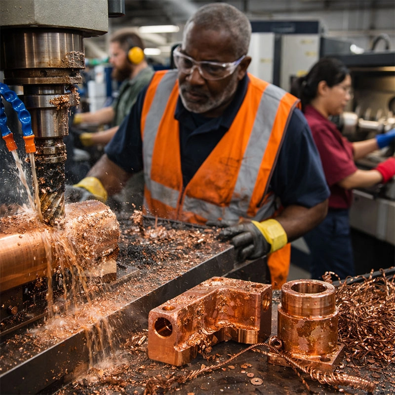
Copper cnc machining decisions should start with function, not with a generic machining label. Buyers get better results when they define how the part will be used, which dimensions control assembly, what material behavior matters, and how the supplier will inspect the finished work. For this topic, the important issues are conductive and thermal parts, burr control, soft material handling, clamping marks, and coolant strategy. A capable supplier should be able to explain the process route, likely risk points, quotation assumptions, and inspection evidence before production begins.
Quick Answer
The practical answer is to match the drawing to a manufacturing route, then confirm material, tolerance, finish, quantity, and inspection before approving the order. If the part has mostly milled faces, pockets, slots, and holes, review CNC milling service capability. If it includes round features, shafts, bushings, or threads, include CNC turning service capability in the discussion. For buyer-side risk control, ask how the shop will hold the part, which features are critical, and whether any finish or secondary process changes final dimensions.
Key Takeaways
- Define the functional dimensions before asking suppliers to quote every feature as critical.
- Send a 2D drawing with tolerance notes and a 3D model for programming reference.
- Confirm material grade, heat condition, surface finish, and inspection report requirements early.
- Ask the supplier to identify difficult features, tool access issues, and possible design changes.
- Use sample approval or first article checks when the part is new, tight, cosmetic, or assembly-critical.
What Buyers Usually Need to Know
Most problems in custom machining come from unclear assumptions. A supplier may quote one setup while the buyer expects multiple controlled operations. A buyer may request a tight tolerance on the full drawing while only one bore or mounting face actually affects the assembly. For copper cnc machining, the conversation should make those assumptions visible before the purchase order is issued.
The RFQ should include units, drawing revision, STEP file, material grade, quantity, surface finish, critical dimensions, and target delivery. When these details are missing, suppliers either pause the quote or make assumptions. A fast answer based on assumptions can look attractive, but it often creates rework later. A better supplier asks clear questions and records the answers.
Capability should be checked against the part shape. A shop with CNC metal machining capability may handle many related jobs, but the buyer still needs to know whether the part will be milled, turned, ground, cut by EDM, drilled, or finished by a partner. Process route clarity is the first sign that the quotation is built on real manufacturing thinking.
| Buyer Question | Why It Matters | Useful Evidence |
|---|---|---|
| Which process will make the main features? | Process choice affects setup count, accuracy, cost, and lead time | Supplier explains milling, turning, EDM, grinding, drilling, or finishing route |
| Which dimensions are functional? | Critical dimensions need better control than clearance or cosmetic areas | Marked drawing, datum notes, inspection plan |
| Which material condition is required? | Grade, temper, hardness, and stress condition change machining behavior | Material certificate or written grade confirmation |
| What happens after machining? | Deburring, anodizing, plating, polishing, or heat treatment can change size and appearance | Finish specification and post-finish inspection method |
Material and Process Considerations
Material changes cutting speed, tool wear, clamping force, burr behavior, and finishing results. Aluminum is usually easier to machine and finish, stainless steel needs more attention to heat and work hardening, brass and copper require careful burr and dent control, and engineering plastics can move under heat or clamping pressure. For copper cnc machining, material selection should support the part’s function rather than only the lowest raw material price.
The process route should match both material and geometry. Deep pockets, small internal radii, long shafts, thin walls, fine threads, and cosmetic faces each require different planning. Buyers should ask whether the supplier sees any design feature that raises risk. If the supplier recommends a larger radius, a different stock size, or a changed tolerance, ask for the reason and the expected effect on cost and quality.
When finishing is required, discuss it before machining starts. Anodizing, plating, passivation, polishing, blasting, coating, and heat treatment may change dimensions, surface appearance, or edge condition. A controlled supplier will connect machining allowance, masking, inspection, and packaging rather than treating finishing as an afterthought. Relevant finishing choices can be checked through quality assurance process.
Tolerance, Surface Finish, and Quality Checks
Tolerance should be tied to function. A general tolerance may be enough for clearance edges, while a bearing diameter, threaded hole, sealing face, or locating surface may require a tighter limit and a clear datum. Buyers should avoid applying strict tolerance across the whole drawing unless the part truly requires it, because unnecessary precision raises cost and may increase rejection risk without improving performance.
Inspection should be planned before production. Calipers may be enough for noncritical outside dimensions, but bores, threads, flatness, profile, runout, and surface roughness often need gauges, micrometers, CMM checks, height gauges, pin gauges, or functional fit tests. For copper cnc machining, ask which tool will verify each critical feature and whether the report covers first article, sampling, or full inspection.
Surface finish needs clear language. Words like smooth, clean, or nice are not enough when mating, sealing, sliding, corrosion, or appearance matters. Use Ra values where function requires them and visual notes where cosmetic faces matter. If finish follows machining, confirm whether dimensions are checked before or after finishing through surface treatment options.
| Factor | Typical Risk | Practical Control |
|---|---|---|
| Tight tolerance | Higher cost, slower machining, more inspection | Apply tight limits only to functional features |
| Thin walls or deep pockets | Vibration, distortion, tool reach limits | Use larger radii, balanced walls, and realistic flatness notes |
| Cosmetic finish | Color variation, handling marks, unclear acceptance | Define visible faces and approve samples when needed |
| Repeat order | Different lot, tool wear, undocumented changes | Keep revision, process, and inspection records |
Cost Factors and Quotation Details
Cost depends on more than part size. Setup time, programming, material stock, tooling, machine time, number of operations, inspection, finishing, packaging, and batch size all affect the final quote. A small part with deep features and tight tolerances can cost more than a larger simple plate. A large batch may justify fixture work that would not make sense for a one-off sample.
Buyers can improve quote accuracy by separating must-have requirements from preferences. State which features control assembly, which surfaces are cosmetic, which dimensions may follow general tolerance, and what report is required. If the supplier has to guess, the quote may change after technical review. Cost-focused topics can also be compared against CNC machine shop capability when drawing changes are possible.
Lead time should be broken down into material purchase, programming, setup, machining, finishing, inspection, packing, and shipment. Finishing and inspection often create delays that buyers do not see in a simple machine-time estimate. Ask for a realistic timeline and identify which step has the highest risk of delay.
Design Tips for Better Machining Results
Good design makes machining predictable. Use accessible features, practical internal radii, balanced wall thickness, clear datums, standard threads, and realistic hole depths. Avoid deep narrow pockets, very thin unsupported walls, tiny corner radii, and tight tolerances on nonfunctional features. These changes often lower cost while improving consistency.
For copper cnc machining, design review should focus on conductive and thermal parts, burr control, soft material handling, clamping marks, and coolant strategy. If a feature is difficult but not functional, simplify it. If a feature is critical, mark it clearly and allow the supplier to plan the correct process. Tool access, clamping surface, burr direction, and finishing allowance should be considered before the drawing is released.
When the part is still being developed, use prototype or low-volume stages to learn from the design. A sample can reveal fit issues, burr problems, coating changes, or tolerance conflicts. It is cheaper to update the drawing after a controlled sample than to repair a full batch after shipment.
Common Buyer Mistakes to Avoid
One common mistake is comparing prices without comparing assumptions. If one supplier includes material certification, surface treatment, inspection report, and protective packaging while another quotes machining only, the prices are not equivalent. Ask each supplier to state what is included and what is excluded.
Another mistake is sending only a 3D model. The model helps programming, but the drawing carries tolerances, threads, material notes, finish requirements, datum references, and revision control. For copper cnc machining, a missing drawing often leads to arguments about what should have been inspected or finished.
Buyers also overlook packaging. Sharp edges, polished faces, threads, thin walls, and precision bores can be damaged after inspection if parts are packed loosely. Packaging method should match the part’s risk and should be confirmed before shipment, especially for export orders.
Supplier Selection Checklist
A useful supplier review is technical and specific. Ask for the process route, material confirmation, fixture concept, inspection method, finishing plan, and lead time breakdown. The supplier does not need to expose every internal detail, but it should be able to explain how risk will be controlled.
| Checklist Item | Good Response | Warning Sign |
|---|---|---|
| Drawing review | Supplier identifies critical dimensions and unclear notes | Supplier quotes with no technical questions |
| Process fit | Supplier explains setups and secondary operations | Supplier only lists machines generally |
| Inspection plan | Supplier names tools and report format | Supplier says quality is checked without details |
| Revision control | Supplier confirms file version and change process | Supplier relies on informal messages |
Specification Sheet to Request
Before production, request a simple specification sheet covering drawing revision, 3D file name, material grade, quantity, finish, tolerance notes, critical dimensions, inspection report, packaging, and delivery terms. This sheet keeps engineering, purchasing, quality, and supplier teams aligned.
For repeat orders, the same sheet prevents silent changes. If material stock, finish partner, inspection method, or packaging changes, the buyer can review the difference before shipment. This is especially important when copper cnc machining parts are used in assemblies or ordered across several batches.
Copper CNC Machining Deep-Dive Notes
The most important judgment for copper cnc machining is knowing which requirement truly drives performance. If the part is a prototype, fast learning may matter more than cosmetic perfection. If it is a repeat production component, stable process control and inspection records may matter more than the fastest quote. If the part is visible to customers, handling and finishing should be planned with the same care as dimensions.
Suppliers should be encouraged to flag manufacturability issues. A larger internal radius, modified thread depth, adjusted wall thickness, or changed finish sequence can reduce cost and risk. The buyer should evaluate each suggestion based on function, assembly, cost, and schedule rather than accepting or rejecting changes automatically.
For higher-risk parts, use a first article approval step. Measure critical dimensions, test fit with mating parts, review burrs, check finish, and document any accepted deviations. Once the sample is approved, update the drawing or specification so production follows the approved standard. That discipline is what turns a one-time sample into a repeatable purchasing process.
Quotation review for copper cnc machining should include a short risk discussion, not only a unit price. Ask the supplier which feature is most likely to drive cycle time, which tolerance is most difficult, whether the material is standard stock, and whether finishing or inspection creates a separate lead time. These answers help the buyer understand why two quotations may differ even when the drawing is the same.
Inspection planning should also separate first-piece approval from batch control. The first piece confirms that the program, fixture, material, and drawing interpretation are correct. Batch inspection confirms that the process stays stable as tools wear, operators change shifts, or material lots vary. For copper cnc machining, both checks can matter when parts must fit an assembly or repeat across several orders.
Communication should be documented in a way that survives staff changes. If the buyer approves a larger corner radius, accepts a minor tool mark, changes a finish, or allows a substitute material, that decision should be written into the drawing, purchase specification, or deviation record. A message buried in a chat thread is easy to miss when the next batch is ordered.
Packaging and handling deserve a line in the purchase requirements. Precision parts can pass inspection and still arrive unusable if threads rub together, cosmetic faces are scratched, thin walls are bent, or moisture reaches bare steel. Ask for trays, separators, oil paper, caps, bags, or carton reinforcement where the part geometry justifies it. The right packaging method is part of the delivered quality, not an optional extra.
If the design is still changing, buyers should avoid locking a large batch too early. A small sample or pilot run can expose burrs, assembly interference, coating thickness issues, tolerance conflicts, or unexpected cost drivers. Once those details are corrected, the production batch becomes less risky. This staged approach is especially useful when copper cnc machining parts combine tight dimensions with visible surfaces or secondary finishing.
Supplier capability should be judged by the questions the supplier asks. A useful supplier will ask about datums, mating parts, finish class, inspection reports, material grade, and delivery constraints. A weak supplier may simply agree to every requirement without explaining how it will be controlled. Buyers should prefer the partner who makes hidden risk visible before production starts.
Finally, keep a record of what worked. After an accepted order, save the final drawing, approved sample notes, inspection report, finish reference, packing photos, and supplier comments. The next order can then start from a known standard instead of repeating the same technical discussion. This habit improves repeatability and makes copper cnc machining purchasing easier over time.
For acceptance, define what happens if only a noncritical feature is outside the drawing while the functional areas pass. Some buyers allow a documented deviation for prototypes or internal fixtures, while production parts may require rework or remake. Agreeing on this decision path before shipment makes copper cnc machining projects easier to manage when small issues appear.
For scheduling, ask the supplier to identify the latest date for drawing freeze, material purchase, machining start, finishing release, inspection, and packing. A clear timeline helps the buyer understand which change requests are still practical and which ones will reset delivery. That clarity is often the difference between a controlled order and a rushed recovery.
Conclusion
Copper cnc machining sourcing works best when buyers define function, material, tolerance, finish, inspection, and delivery expectations before production. The strongest supplier is not simply the one with the fastest quote; it is the one that can explain the manufacturing route, identify risks, and provide evidence that the finished parts match the drawing. Clear RFQ data and practical design decisions reduce cost, delays, and rework.
FAQ
What information should I send for copper cnc machining?
Send a 2D drawing, STEP file, material grade, quantity, finish requirement, tolerance notes, critical dimensions, inspection report needs, and target delivery date.
How can I reduce cost without weakening the part?
Use practical tolerances, larger internal radii, accessible features, standard materials, and clear finish notes. Ask the supplier which design details add the most machine time.
When should I request a first article report?
Request it when the part is new, tight tolerance, cosmetic, assembly-critical, or used for repeat production. The report should focus on the dimensions and features that affect function.