

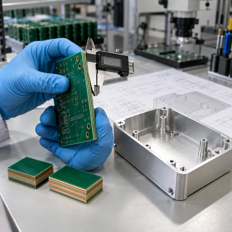
FR4 PCB material is a family of glass-reinforced epoxy laminates, not one interchangeable specification. A useful purchasing package names the laminate or performance class, finished thickness, copper weights, stackup, surface finish, impedance requirements, compliance requirements, and the tests used for acceptance.
This guide explains how to turn “FR4” into a quote-ready material requirement and how that choice affects a machined enclosure. MTSPi manufactures mechanical parts; it does not claim PCB fabrication capability. Confirm laminate, fabrication, and electrical-test requirements with the selected board supplier.
What FR4 Means and What It Does Not
FR4 describes a flame-retardant grade family commonly based on woven glass reinforcement and epoxy resin. It does not identify one resin system, one glass-transition temperature, one dielectric constant, or one approved operating temperature. Two materials described as FR4 can have materially different thermal and electrical properties.
A flame-retardant grade is also not a substitute for a product-level compliance decision. When a flame classification matters, request the laminate manufacturer, exact product designation, relevant UL file, minimum thickness covered, and the board fabricator’s applicable recognition. Do not infer approval from the green color of a finished board.
Use the Datasheet, Not a Generic FR4 Number
Published laminate data show why a generic callout is incomplete. For example, an Isola low-Tg FR4 product lists a 135 C Tg, while a high-Tg FR4 product lists a 180 C Tg. Their decomposition temperature, Z-axis expansion, moisture absorption, dielectric properties, and copper options also differ. These values belong to the named products and test methods; they are not universal FR4 constants.
| Property | What it describes | Why a buyer cares |
|---|---|---|
| Tg | Transition in the resin system’s mechanical behavior | Useful for thermal-process and dimensional-stability review, but not a maximum service-temperature rating |
| Td | Decomposition temperature under a stated test method | Helps compare resistance to thermal degradation; it does not replace reflow qualification |
| Z-axis CTE | Expansion through the board thickness | Relevant to plated-through-hole and multilayer reliability during thermal cycling |
| Dk | Relative permittivity at a stated frequency and method | Affects transmission-line geometry and propagation; use the fabricator’s design value |
| Df | Dielectric loss at a stated frequency and method | Matters when insertion loss and high-frequency performance are design constraints |
| CTI | Comparative tracking index under a defined test | May influence insulation coordination, but required creepage still depends on the applicable safety standard |
| Water absorption | Moisture uptake under a stated conditioning method | Can affect processing, dimensional behavior, and electrical performance |
Do not compare isolated values measured by different methods as if they were directly equivalent. Record the test method, frequency, conditioning, and whether a value is typical or guaranteed.
Specify the Thermal Requirement as a Process Window
“High Tg” is useful shorthand only after the assembly process is known. Document the soldering profile, number of expected thermal excursions, board thickness, copper distribution, via construction, and reliability requirement. Tg, Td, time-to-delamination data, and expansion behavior answer different questions.
For lead-free assembly, ask the fabricator to propose a laminate qualified for the agreed stackup and reflow exposure. A high Tg alone does not guarantee low Z-axis expansion, adequate time to delamination, or a robust plated-through-hole construction. If the board will operate hot after assembly, treat continuous operating temperature as a separate application requirement.
Define the Electrical Requirement Before Naming a Substitute
Standard FR4 may be suitable for many digital and low-frequency products, but there is no defensible universal frequency at which it suddenly stops working. Trace length, loss budget, edge rate, impedance tolerance, copper roughness, weave effects, temperature, and moisture all influence the result.
For controlled impedance, provide the target, tolerance, layer reference, and test-coupon requirement. Let the PCB fabricator close the stackup using the actual laminate and copper system, then return the proposed geometry for electrical approval. The HDI stackup and mechanical-integration guide shows how to coordinate that proposal with the enclosure revision.
Move to a characterized low-loss or RF laminate when analysis shows that FR4’s loss or property variation consumes the available margin. Use a metal-core construction when heat spreading dominates and the electrical design supports it. Use a flex construction when the circuit must bend. These are requirement-driven changes, not automatic upgrades.
Make Thickness and Copper Unambiguous
A nominal finished thickness such as 1.6 mm does not define the dielectric structure. State the finished-thickness tolerance, layer count, copper weight by layer, plating assumptions, and approved stackup. If connector fit, card guides, edge contacts, or a compression interface depend on thickness, identify that dimension as a mechanical interface.
Copper should be stated as starting and/or finished copper where relevant. A plated outer layer does not necessarily finish at its starting foil thickness. Heavy copper changes etching, spacing, thermal behavior, and stackup balance, so it belongs in the first quotation package rather than a later note.
Choose Surface Finish From Assembly and Storage Needs
Surface finish affects solderability, pad flatness, storage, rework, and cost. Lead-free HASL, ENIG, OSP, immersion silver, and other options are not interchangeable defaults. Fine-pitch components may need a flatter finish, while storage duration and handling conditions can rule out an otherwise economical option.
Ask the assembly supplier to approve the finish together with the component package and soldering process. If edge contacts, wire bonding, repeated mating, or a specific shelf-life requirement applies, state it explicitly and request the appropriate thickness and inspection evidence.
Coordinate the PCB With the Machined Enclosure
The laminate choice reaches the enclosure through finished thickness, bow and twist, mounting-hole location, connector position, thermal-interface compression, and electrical clearance. A CAD model containing only the bare board outline is not enough for a reliable fit review.
- Use shared datums for the board holes, enclosure standoffs, and connector openings.
- Model maximum component height, keep-out zones, screw heads, washers, and cable bend space.
- Define the acceptable board-thickness range where card guides or edge slots locate the assembly.
- Review thermal-pad compression without forcing the PCB to become a spring.
- Keep conductive hardware and machined bosses outside the electrical team’s required clearances.
- Inspect first-article board-to-housing fit with the populated assembly or a controlled representative fixture.
Send the approved board envelope and interface drawing when discussing machined enclosure features. MTSPi can review the mechanical component, tolerances, material, and inspection scope without representing the PCB fabrication itself.
A Quote-Ready FR4 PCB Specification Checklist
| RFQ field | Minimum useful content | Evidence to request |
|---|---|---|
| Laminate | Manufacturer/product or approved performance class; Tg/Td/CTE and compliance requirements | Datasheet, certificate of conformance, UL file where applicable |
| Construction | Layer count, proposed stackup, finished thickness and tolerance | Approved stackup drawing and revision |
| Copper | Per-layer starting/finished requirement as applicable | Stackup and cross-section plan |
| Electrical | Impedance targets and tolerances, test coupons, net test requirement | Impedance report and electrical-test record |
| Thermal process | Assembly profile, expected cycles, and special operating environment | Material suitability confirmation and agreed qualification |
| Finish | Named finish, thickness where relevant, storage/assembly constraints | Process certificate or inspection result as required |
| Mechanical | Outline, hole tolerances, bow/twist limit, connector and enclosure interfaces | First-article dimensional report |
| Compliance | Applicable IPC class, RoHS/REACH or product-specific requirements | Agreed certificates and traceability documents |
Include Gerber or ODB++ data, drill files, fabrication drawing, stackup, netlist where required, assembly constraints, and revision identifiers. Ask suppliers to list every proposed deviation instead of silently substituting an available laminate.
When to Stay With FR4 and When to Switch
Stay with a qualified FR4 product when its documented electrical, thermal, mechanical, regulatory, and supply requirements fit the application. Consider a higher-performance laminate when repeated thermal processing or reliability requirements exceed the proposed standard material. Consider low-loss/RF material when simulation and test budgets require tighter and lower dielectric loss. Consider metal-core material for a heat-spreading architecture, polyimide-based flex for controlled bending, or another substrate when the product requirement clearly demands it.
The correct decision is the least exotic material system that passes the complete requirement set with manufacturing margin. A premium laminate cannot repair an incomplete stackup, poor thermal design, or an enclosure that loads the board incorrectly.
Frequently Asked Questions
Is all FR4 the same?
No. FR4 is a grade family. Resin systems, Tg, Td, expansion, moisture absorption, Dk, Df, approvals, and available constructions vary by product.
Does a higher Tg automatically mean a better PCB?
No. It can support certain thermal requirements, but reliability also depends on expansion, decomposition behavior, stackup, via construction, process control, and the actual thermal cycle.
Can I specify only 1.6 mm FR4 and 1 oz copper?
That is enough for a rough budgetary discussion, not a controlled build. Add the exact or approved laminate class, stackup, finished-thickness tolerance, copper definition, surface finish, electrical requirements, and acceptance tests.
At what frequency must FR4 be replaced?
There is no universal cutoff. Use the channel loss budget, trace length, material data at the relevant frequency, impedance tolerance, environment, and validation results to decide.
What should the enclosure supplier receive?
Provide the approved board outline, thickness range, hole and datum scheme, populated height envelope, connector locations, keep-outs, thermal interfaces, and assembly sequence. Use the engineering contact page to submit the mechanical package for review.
Technical reference basis: IPC technical resources on laminate thermal behavior and moisture; published Isola FR4 laminate data; UL material-recognition records; Rogers guidance on high-frequency laminate selection. Values in this article are explanatory only. Use the named product’s current datasheet and the applicable design standard for procurement.