

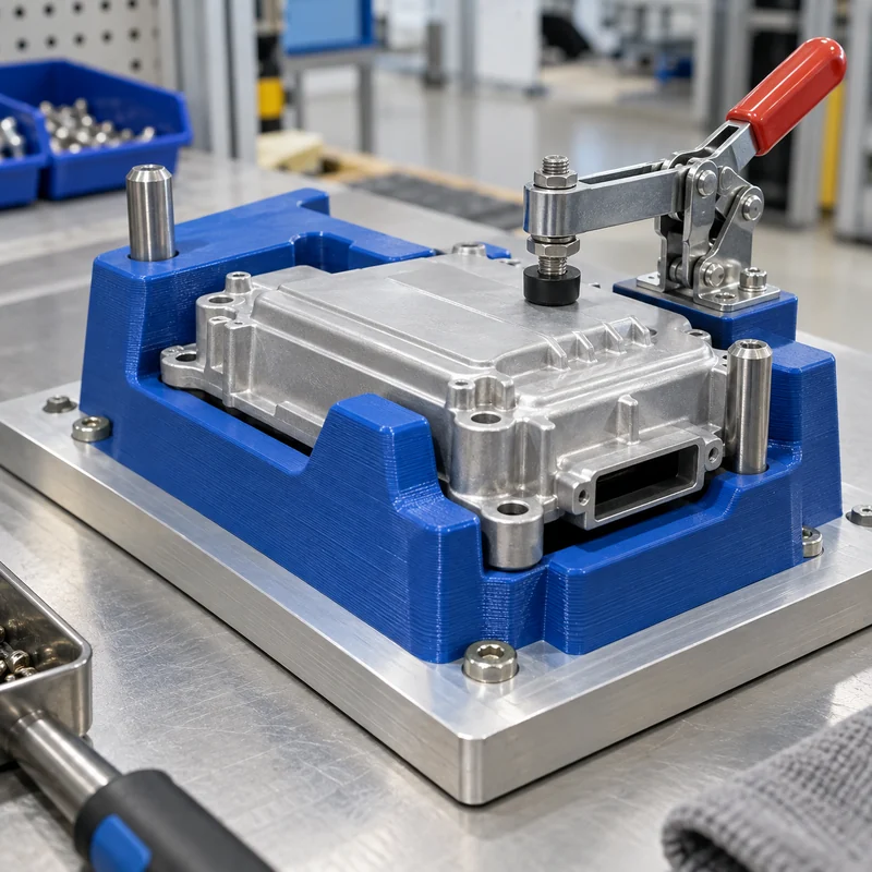
3D printed tooling is useful when a manufacturing aid needs complex contact geometry, quick revision, or low weight. CNC machined tooling is often the stronger candidate when sustained load, wear, heat, or a demanding locating interface controls the design. A hybrid fixture can combine a printed nest with machined datums, steel bushings, and replaceable wear components.
The selection should begin with the operation and its acceptance criteria. A tray for arranging components, a drill jig, and a machining fixture can look similar while having very different failure consequences. Compare complete tools that perform the same job rather than comparing material prices alone.
Start With the Operation and the Forces
Document the workpiece, locating sequence, applied forces, operator actions, and expected cycle count. Include the weight of the part, clamp forces, cutting or drilling loads where relevant, and any loads created during unloading. A tool that holds a component securely on a bench may behave differently when mounted vertically or accelerated by automation.
Define the failure modes worth preventing: movement, excessive deflection, crushed contact pads, worn locating holes, loose inserts, or heat distortion. Identify where a displaced component could damage equipment or expose an operator to harm. Select the tool architecture and validation effort to match those consequences.
Distinguish a Jig From a Fixture
A fixture locates and supports a workpiece during an operation. A jig also guides a tool, for example through a drill bushing. This distinction matters because the guide interface may encounter concentrated wear, friction, and forces that an assembly nest never experiences.
Formlabs’ manufacturing guidance describes both as customized production aids. The practical design lesson is to map each interface separately. A comfortable printed handle can be appropriate even when the drill guide, locating pin, and base plate require metal. Select a construction by function rather than requiring every feature to use one manufacturing process.
Compare the Three Tooling Routes
| Route | Useful characteristics | Items to validate |
|---|---|---|
| Printed polymer tool | Complex nests, low weight, rapid geometry changes | Orientation, creep, heat, chemical exposure, surface wear |
| Machined metal tool | Rigid bases, durable datums, accessible precision interfaces | Clamping distortion, mass, corrosion, machining access |
| Hybrid assembly | Printed geometry combined with durable locating and guiding elements | Insert retention, tolerance accumulation, replaceability, joint stability |
No row guarantees a particular tolerance or service life. Those outcomes depend on material, geometry, processing, inspection, and use. Compare the actual proposed constructions, including post-processing and any machining, rather than a generic label such as engineering resin or aluminum.
Design Datums and Support Before Adding Clamps
Choose repeatable locating features that constrain the intended motion without unnecessarily overconstraining the workpiece. Place supports under locations that carry clamp or process loads. A clamp acting between distant supports can bend the part and create a false inspection result.
Provide clearance for burrs, debris, and nonfunctional surfaces. Do not let a large cosmetic surface accidentally become the locating datum unless the drawing permits that approach. Where the operation needs accurate reference features, discuss machined base plates and locating surfaces early enough to coordinate them with the nest.
Treat Printed Orientation as a Design Variable
Printed properties and surface quality can depend on build orientation, layer bonding, support placement, and post-curing or conditioning. Avoid assuming that a material datasheet represents every direction in the finished tool. Ask the supplier which surfaces need supports and how their removal affects the workpiece contact.
Allow for the processing sequence. An insert installed into a thin boss can split or distort it; a threaded connection repeatedly tightened into polymer can lose retention. Provide sufficient surrounding material and validate the selected insert installation method using representative samples. There is no universal wall thickness that qualifies every tool.
Put Metal Where Wear and Contact Demand It
Steel drill bushings, locating pins, threaded inserts, and replaceable pads can protect a printed body from repeated contact. The interface holding those components matters as much as the components themselves. Define whether the fit is pressed, bonded, mechanically retained, or assembled through a separate metal structure.
Keep the load path understandable. For a hypothetical assembly nest, a printed shell might position a cosmetic housing while a metal stop reacts the clamp force. That arrangement needs a review of the housing support and stop position; adding a steel pin alone does not make the entire fixture rigid.
Check Heat, Coolant, Cleaning, and Time Under Load
Service conditions can overturn an otherwise attractive tooling choice. Exposure to cleaning agents, oils, humidity, ultraviolet light, soldering heat, or hot components should be considered using the actual material and exposure duration. A brief temperature rating cannot establish long-term dimensional stability.
Also review creep under sustained clamping and the temperature reached during repeated cycles. A fixture left loaded overnight may behave differently from a tool released after each short operation. Record the intended cleaning method and storage condition alongside the operating instructions.
Validate the Tool Against a Measurable Acceptance Plan
Inspect the locating features before loading a part, then verify the part position under the intended clamp condition. Run representative cycles and inspect again for movement, wear, loose hardware, and permanent deformation. Compare repeated load and unload measurements where repeatability controls the process.
For inspection fixtures, assess the contribution of the tool and operator to measurement variation. For production aids, agree the permissible workpiece movement and part quality results. The inspection planning resources provide context for defining critical features and reports with MTSPi.
Compare Lifetime Cost and Revision Risk
Include design, printing or machining, hardware, finishing, inspection, validation, downtime, repairs, and replacement in the comparison. A low initial cost may be attractive for a frequently revised prototype, while a stable production line may justify durable replaceable wear surfaces.
Freeze the approved CAD revision and material specification after validation. Mark tools so operators can distinguish old and new versions. Maintain spare wear components when replacement time affects production, and revalidate meaningful changes in build orientation, material, or supplier.
Frequently Asked Questions
Can a printed fixture replace an aluminum fixture?
Sometimes. Compare stiffness, load, temperature, wear, repeatability, and lifetime requirements using a representative tool and operation.
Can drill bushings be installed in printed tooling?
Yes, with a suitable retention design. Validate alignment, local support, retention, and wear under the intended drilling conditions.
What should I send for a tooling quote?
Send the workpiece model and drawing, operation description, datums, loads, environment, cycle expectations, and acceptance requirements. Confirm the proposed mechanical scope through the project contact page.