Good sheet metal bracket design begins with the load path, mounting interfaces, material condition, and bend process. Hole placement, flange length, internal radius, fastener access, finish, and inspection must work together. A bracket that is easy to unfold in CAD can still be difficult to bend or impossible to assemble.
Use the following process to release a bracket that can be quoted, manufactured, measured, and installed consistently. Numerical bend rules should come from the chosen supplier’s material and tooling capability rather than being copied from an unrelated process.
Define Loads and Interfaces Before Choosing a Shape
Identify what the bracket supports, where loads enter and leave, and whether those loads are static, cyclic, impact-driven, or caused by vibration. Include cable pull, installation force, equipment movement, and fastener preload where relevant. A short flange supporting a sensor has different requirements from a cantilever carrying a motor.
Specify the critical mounting planes and hole locations relative to the assembly. Decide which direction may accommodate adjustment and which must locate accurately. A slot can simplify installation, but it also changes how the joint transfers load and resists movement after tightening.
Select the Form Around Stiffness and Assembly
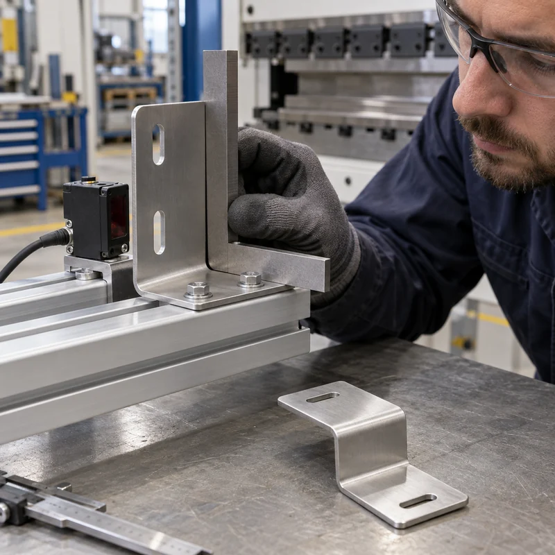
An L bracket offers two perpendicular mounting faces. A U form can support a component between two legs. A Z form creates an offset, while a hat or channel section can increase bending stiffness compared with a flat strip. These names describe geometry rather than a guaranteed load capacity.
Consider bends, returns, ribs, or separate supports before simply increasing thickness. Additional geometry can improve stiffness, but may introduce tooling restrictions or obstruct installation. Check the complete assembly, including the space required to insert and tighten each fastener.
Choose Material Grade and Condition
| Material family | Reason to consider it | Design question |
|---|---|---|
| Carbon steel | Useful strength and economical fabrication | What corrosion protection and finish are required? |
| Stainless steel | Corrosion resistance in suitable environments | Which grade and condition suit bending and service? |
| Aluminum | Low mass and suitable corrosion performance | Is the selected alloy and temper appropriate for the bend radius? |
State thickness and tolerance, alloy or grade, temper or condition, and finish. Different aluminum tempers and stainless grades can behave differently during forming. Check material availability before designing around an unusual thickness that complicates sourcing.
Agree Bend Radius and Minimum Flange With the Shop
The achievable bend depends on material, thickness, grain direction, tooling, and forming method. A flange must be long enough to engage the tooling and allow the operation. A tight return or closely spaced bend can create a tool collision even when each bend is individually feasible.
Protolabs’ published guidance illustrates that bend geometry and feature placement are process-dependent. Use the actual fabricator’s rules for production. Define whether inside radius is a controlled functional requirement or may follow approved standard tooling, and keep equivalent bends consistent where practical.
Move Holes Away From the Bend-Deformation Zone
A hole or slot close to a bend can stretch, shift, or become distorted. Review feature distance using the selected radius, thickness, and tooling. If a critical hole must sit close to a bend, discuss a relief feature, a changed sequence, or post-forming machining.
Bend reliefs can reduce tearing and control the transition where a bend ends. Their geometry should allow the tooling and material to form cleanly without leaving a sharp, unsafe projection or an unacceptable stress concentration. Treat reliefs as part of the functional design.
Plan Fasteners and Tool Access in Three Dimensions
Model screw heads, nuts, washers, captive hardware, mating parts, and installation tools. Check the path for bringing components together, not just the final position. A fastener may fit in the completed model while remaining inaccessible to a socket or driver.
For self-clinching hardware, use the hardware manufacturer’s requirements for sheet thickness, hole size, edge distance, material hardness, and installation. For tapped features, verify available thread engagement. A separate nut or a machined insert may be more suitable than a short thread in thin sheet.
Control Functional Dimensions Without Overconstraining the Drawing
Choose datums that match how the bracket mounts. Focus tolerances on the interfaces that matter: locating holes, mounting planes, offset, angle, or a clearance envelope. Do not apply a tight general tolerance to every formed edge when only one interface requires precision.
Bend-angle variation accumulates over distance, so a small angular difference can produce a larger displacement at a long flange tip. If the application requires a precise final relationship, agree an inspection setup and consider a finishing operation or an adjustable interface.
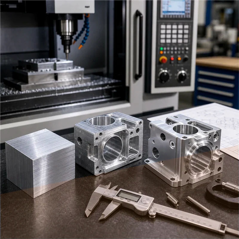
Where a bracket needs critical bores or datum surfaces beyond the forming route, discuss secondary machining of mounting features. Provide the formed blank and finished requirements together so clamping and stock can be reviewed.
Include Finish and Edge Condition in Fit Checks
Paint, powder coating, plating, and anodizing can affect holes, slots, electrical contact areas, and cosmetic expectations. Define masking where needed and specify whether dimensions apply before or after finish. Coating buildup can interfere with a close slot even when the unfinished bracket passes inspection.
Remove hazardous burrs and define acceptable edge treatment. Where electrical bonding matters, coordinate contact surfaces and corrosion protection with the responsible designer. The surface treatment overview helps compare mechanical finish requirements before release.
Validate the Bracket in Its Real Assembly
Inspect first articles using the mounting condition defined on the drawing. Confirm holes, angles, clearances, fastener access, and the order of assembly. Avoid forcing a flexible part flat during inspection unless that restraint represents the specified mounting condition.
Test representative loading and vibration where the application requires it. If a prototype is made by a different process, verify that it still represents the production material, bend condition, and joint behavior. Keep approved deviations visible rather than relying on a successful hand-fit sample.
Frequently Asked Questions
What bend radius should I use?
Use a radius supported by the selected material, condition, thickness, tooling, and application. Obtain the fabricator’s recommendation before final release.
Can I place a hole directly beside a bend?
Sometimes, but deformation and tooling access must be reviewed. Moving the hole, adding a relief, or machining afterward may be necessary.
Is thicker sheet always the best way to stiffen a bracket?
No. A suitable section shape or shorter load path may improve stiffness more efficiently, subject to strength and manufacturing validation.
What belongs in the quotation package?
Supply the formed model, drawing, material, finish, quantity, functional datums, loads, and acceptance requirements. Confirm the appropriate manufacturing scope through the engineering enquiry page.