

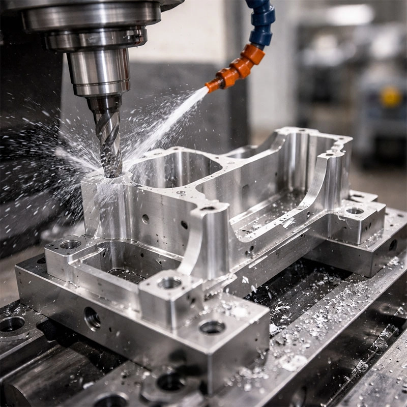
Machining thin-walled aluminum parts is a common yet challenging task in CNC workshops. This guide breaks down the process into five actionable expert tips, focusing on practical strategies to prevent chatter, distortion, and tool failure, helping you achieve precise, high-quality results every time.
Understanding the Challenge
So, you’ve got a job for machining thin wall aluminum components. It might be a lightweight aerospace bracket or a complex electronic enclosure. I get it—these parts look simple on the drawing but can be a real headache on the shop floor. The core issue is rigidity, or rather, the lack of it. When you’re dealing with thin-wall aluminum machining, the material is prone to flexing, vibrating (that awful chatter sound!), and distorting from cutting forces and heat. It’s like trying to slice a ripe tomato with a dull knife; you end up crushing it instead of getting a clean cut. Successfully machining thin walled aluminum parts isn’t about brute force; it’s a finesse game. Let’s walk through five key areas where a little expert knowledge makes all the difference.
Tip 1: Master Tool Selection and Geometry
Your first line of defense is choosing the right cutter. This isn’t the time for that old, slightly worn end mill. For aluminum thin wall machining, you need tools designed to cut smoothly and efficiently.
Sharp, High-Helix End Mills
Opt for end mills with a high helix angle (around 45° or more) and sharp, polished flutes. A high helix creates a shearing action that lifts chips up and out of the cut cleanly, reducing the force pushing against the thin wall. Tools specifically designed for aluminum milling, often with three flutes, offer an excellent balance of material removal and finish. Remember, a sharper tool requires less cutting pressure, which is exactly what our delicate part needs.
The Climb Milling Strategy
Always use climb milling (also called down milling). In this direction, the cutter teeth engage with the maximum chip thickness at the start of the cut and taper off to zero. This pulls the workpiece into the cutter, minimizing deflection and providing a cleaner surface finish on the thin wall. Conventional milling pushes the workpiece away, which can cause the wall to vibrate and chatter.
Tip 2: Optimize Feeds and Speeds for Stability
Finding the sweet spot in your CNC parameters is crucial. The goal is to maintain a consistent, light chip load. Running too slow can cause the tool to rub and generate excessive heat, softening the aluminum and leading to built-up edge. Running too aggressively will simply bend or break the wall.
We suggest you start with a higher spindle speed and a moderate-to-high feed rate. This might sound counterintuitive, but a faster feed per tooth ensures the cutter is *cutting* more than it’s *rubbing*. It creates thinner, cooler chips that carry heat away. A great resource for dialing in these numbers is the HSMAdvisor software, which specializes in calculating optimal parameters for challenging materials and geometries. The key takeaway for thin wall part machining is to prioritize a stable, continuous cut over maximum material removal rate.
Tip 3: Rethink Workholding and Fixturing
How you hold the part is just as important as how you cut it. Standard vises clamping directly on a thin feature are a recipe for distortion. You need to support the wall directly opposite the cutting forces.
Strategic Support is Key
For internal pockets, use custom soft jaws or fixture plates that match the part’s contour, providing full backing to the thin floor or side wall during machining aluminum thin walls. For external walls, consider strategic clamping away from the cut area and using removable support tabs or “bridges” in your CAD model that are machined away in the final operation. This extra material provides crucial rigidity during the bulk of the CNC milling process.
Consider Vacuum Fixturing
For large, plate-like thin parts, vacuum chucks are a game-changer. They distribute holding force evenly across the entire back surface, virtually eliminating clamping distortion and allowing you to machine most features in a single setup. It’s one of the most effective methods for precision thin wall machining.
Tip 4: Employ Smart Toolpath Strategies
Modern CAM software is your best friend here. Ditch the traditional constant-stepover toolpaths for more intelligent options. Trochoidal or adaptive clearing paths maintain a constant tool engagement angle, preventing the cutter from getting overloaded in corners—a common failure point. For finishing the final wall, use a spring pass. This is a second, identical finishing pass that removes any material that may have sprung back after the first cut due to residual stress or deflection, ensuring true dimensional accuracy for your thin-walled aluminum components.
Tip 5: Proactively Manage Heat and Chip Evacuation
Heat is the enemy of dimensional stability. Aluminum expands when heated, and if the part gets too hot during machining thin sections, it will be out of spec when it cools. Use plenty of coolant, preferably flood coolant, to both control temperature and flush chips away. Re-cutting chips (recutting) is a major source of heat and poor surface finish. For deep pockets, consider peck milling or using an air blast to ensure chips are cleared from the cutting zone. Keeping everything cool and clean is a simple but non-negotiable rule.
Putting It All Together
Mastering thin wall aluminum fabrication is about a holistic approach. It’s the synergy of a sharp, correct tool; stable, calculated cutting parameters; intelligent workholding; smart CAM programming; and diligent thermal management. Start by analyzing your part to identify the most fragile features, then build your process around supporting and cutting them gently. Don’t be afraid to make test cuts on scrap material. With these five expert tips, you’ll transform a daunting job into a routine success, producing strong, precise, and chatter-free thin wall parts that meet the tightest tolerances. Happy machining!