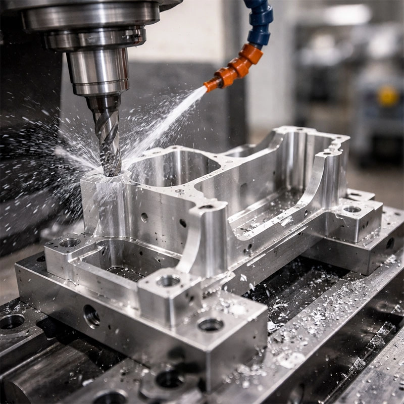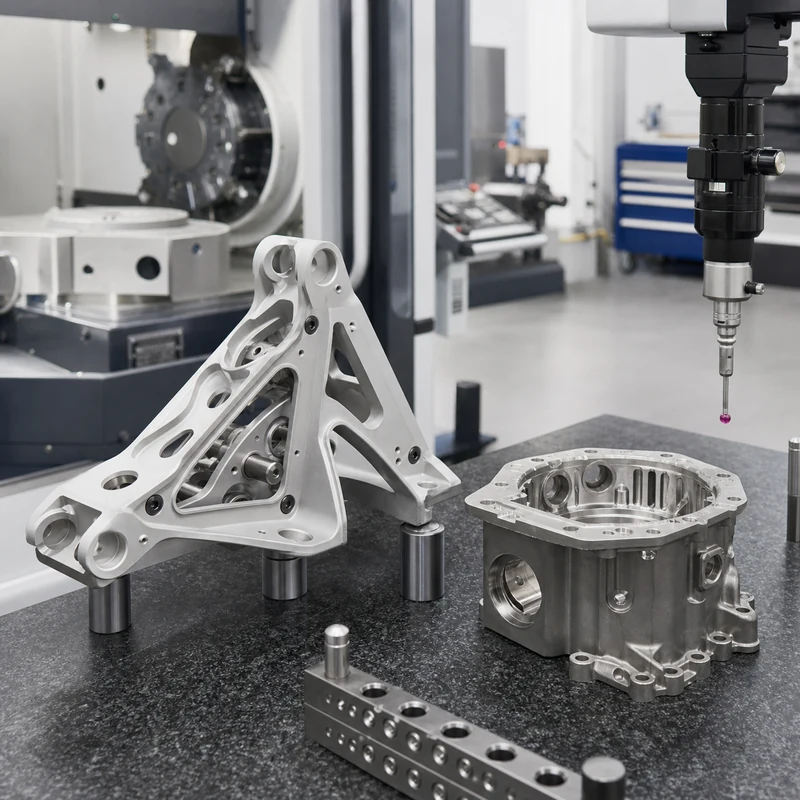
Tight-tolerance aerospace machined parts demand more than accurate equipment. A capable supplier must control process planning, material behavior, fixturing, cutting strategy, inspection, documentation, and repeat production. The best evaluation focuses on how the supplier will manufacture your actual part, not on a generic machine list.
Aerospace components often combine thin walls, pockets, curved surfaces, deep features, critical datums, lightweighting geometry, and demanding materials. MTSPi supports custom CNC machining services with process review, precision machining, and quality assurance for engineering teams that need reliable parts for prototypes and production.
Supplier Evaluation Checklist
| Area | What to Verify | Why It Matters |
|---|---|---|
| Relevant experience | Similar materials, geometry, tolerances, and documentation needs | Aerospace work punishes weak process planning |
| Machine capability | 5-axis milling, turning, mill-turn, stable fixtures, tool reach | The machine path must match part complexity |
| Tolerance control | Repeatability, datum strategy, thermal control, in-process checks | One good prototype is not enough for production |
| Material knowledge | Aluminum, titanium, stainless steel, nickel alloys, engineering plastics | Each material moves, cuts, and finishes differently |
| Inspection system | CMM, gauges, surface checks, reporting, calibration discipline | Critical features must be measurable and traceable |
| DFM support | Early review of walls, radii, setup access, and tolerance stack-up | Small design changes can reduce risk and cost |
| Production readiness | Stable work instructions, tool-life control, lot tracking, packaging | Repeat orders need the same result every time |
1. Confirm Real Aerospace Machining Experience
Ask for examples that resemble your part family: brackets, housings, frames, sensor mounts, manifolds, shafts, spacers, or small precision hardware. A strong supplier should explain how they approach thin walls, datum transfer, residual stress, tool access, burr control, and inspection planning. Vague claims about precision are less useful than a clear manufacturing route.
2. Match Machine Capability to Part Geometry
Complex aerospace parts often benefit from 5-axis machining because multiple faces can be reached with fewer setups. Fewer setups can reduce repositioning error and help preserve true position, profile, and datum relationships. Turning, Swiss-type machining, and mill-turn machining may be better for cylindrical aerospace hardware or small long components.
| Part Type | Likely Process | Reason |
|---|---|---|
| Lightweight brackets | 3-axis or 5-axis milling | Pocketing, profiling, and datum control |
| Complex housings | 5-axis milling | Multi-face access and reduced setup error |
| Bushings and spacers | CNC turning | Efficient control of concentric diameters and faces |
| Small pins and sleeves | Swiss-type machining | Stability for long, small-diameter features |
| Parts with turned and milled features | Mill-turn machining | Lower handling and better feature alignment |
3. Evaluate Tight-Tolerance Process Control
Tight tolerances are held through a controlled chain of decisions. Programming, tool selection, fixture design, roughing and finishing sequence, stress relief, coolant strategy, tool wear monitoring, and final inspection all influence the result. For critical features, ask how the supplier separates roughing from finishing and how they confirm repeatability after the first article.
- Ask which dimensions will be checked in process and which will be checked after finishing.
- Confirm whether datums are machined in the same setup as critical features.
- Review whether thin sections may move after material removal.
- Discuss tool reach, cutter deflection, corner radii, burr risk, and surface roughness.
- Clarify the inspection method for true position, flatness, parallelism, profile, threads, and bores.
4. Check Material Experience
Aerospace parts commonly use high-strength aluminum, titanium alloys, stainless steels, and nickel alloys. Aluminum is efficient to machine but can distort in thin-wall structures. Titanium offers excellent strength-to-weight performance but concentrates heat near the cutting zone. Stainless steels can work harden. Nickel alloys need rigid setups and conservative cutting conditions.
| Material | Common Aerospace Use | Supplier Risk to Discuss |
|---|---|---|
| 7075 aluminum | Lightweight structural brackets and plates | Stress movement, thin walls, anodizing allowance |
| Titanium alloys | High-strength brackets and mission hardware | Heat control, tool wear, surface integrity |
| Stainless steel | Corrosion-resistant fittings and hardware | Work hardening, burrs, passivation needs |
| Nickel alloys | High-temperature components | Tool life, rigidity, cycle time, inspection planning |
5. Review Quality Assurance and Documentation
Inspection capability should be tied to the drawing. CMM inspection may be needed for GD&T and multi-feature relationships. Micrometers, bore gauges, thread gauges, pin gauges, and height gauges may be more efficient for simpler features. For aerospace-style work, ask about inspection reports, material certificates, revision control, calibration, nonconforming-part handling, and packaging protection.
6. Use DFM Before Releasing the Order
DFM review is especially valuable when tolerances, material removal, and geometry interact. A supplier may suggest larger internal radii, clearer datum callouts, revised wall thickness, changed thread depth, selective tight tolerances, or finish allowances. These changes can improve manufacturability without changing the part function.
Questions to Ask Before Selecting a Supplier
- Which machine and setup strategy would you use for this part?
- Which tolerances or GD&T callouts create the highest manufacturing risk?
- How will the part be fixtured without distorting thin walls or datums?
- What inspection equipment will verify the critical features?
- Can you support prototypes and repeat production with the same process plan?
- How are material certificates, inspection reports, and revisions controlled?
How MTSPi Supports Aerospace-Style CNC Projects
MTSPi reviews CAD models and drawings for material, geometry, tolerance, finishing, and inspection risk before production. Our team can support precision milling, turning, 5-axis machining, and documented inspection for demanding machined parts. Share your model, drawing, material requirement, target quantity, and reporting needs through the RFQ page.
Related MTSPi Resources
FAQ
What makes aerospace machined parts difficult?
They often combine tight tolerances, lightweight geometry, thin walls, hard materials, strict datum relationships, and documentation requirements.
Does every aerospace-style part need 5-axis machining?
No. Some parts are better suited to 3-axis milling, turning, Swiss machining, or mill-turn machining. The process should match the part geometry and tolerance plan.