

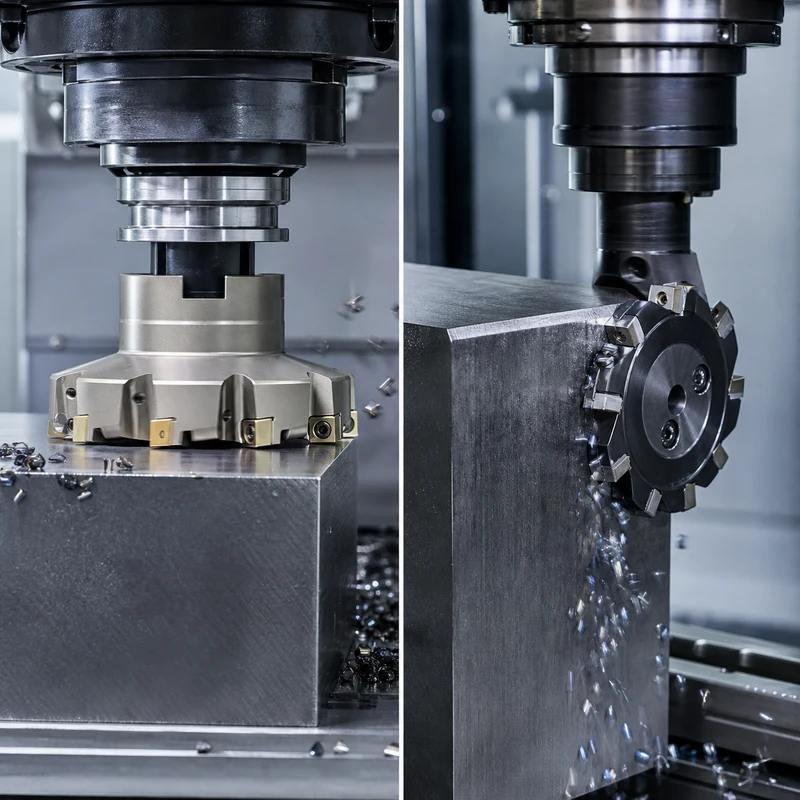
Face milling and peripheral milling describe where a cutter does most of its work. In face milling, cutting edges across the tool face create a surface generally perpendicular to the spindle axis. In peripheral milling, teeth around the cutter circumference generate a surface generally parallel to that axis.
The distinction affects cutter choice, machine orientation, chip thickness, surface texture, workholding, and tool access. Many real parts use both methods in separate operations.
Face Milling vs Peripheral Milling at a Glance
| Factor | Face milling | Peripheral milling |
|---|---|---|
| Primary cutting edges | Face and outer inserts | Teeth around circumference |
| Generated surface | Usually perpendicular to spindle axis | Usually parallel to spindle axis |
| Typical task | Large flat faces and datum planes | Sides, shoulders, slots, and long edges |
| Common cutter | Indexable face mill or shell mill | End mill, slab mill, or side-and-face cutter |
| Surface marks | Sweeping arcs across the face | Lines following cutter travel and tooth engagement |
| Machine demand | Spindle power and stable axial support | Arbor/tool rigidity and controlled radial load |
How Face Milling Works
A face mill spans a broad area and removes stock with multiple inserts. The cutter is normally wider than the intended pass, although large surfaces may need overlapping passes. Lead angle, radial engagement, insert geometry, and cutter position determine force direction and chip thickness.
Face milling is commonly used to establish the first reference plane on plate, square a block, finish a flange, or prepare a sealing face. For consistent results, the machine spindle must be correctly aligned and the work fully supported.
How Peripheral Milling Works
Peripheral cutters engage with teeth on their outside diameter. A vertical machining center often performs this action with an end mill along a wall; a horizontal mill may use a slab or side-and-face cutter on an arbor. The method is effective for shoulders, profiles, deep straight sides, and slots.
Tool stick-out and radial deflection are central concerns. A long end mill may bend away from the work, causing taper, chatter, or a dimensional step. Short tools, balanced radial engagement, and staged finishing passes improve control.
Climb and Conventional Direction
Both methods may use climb or conventional milling. In climb milling, chip thickness starts high and falls toward zero; this often improves finish and tool life on rigid CNC equipment. Conventional milling starts near zero chip thickness and can rub before cutting, but it may be useful with certain manual-machine backlash conditions or unstable surface scale. Machine condition and workholding determine the safe choice.
Choosing the Right Method
- Identify the surface orientation. A broad top face favors a face mill; a vertical wall favors peripheral engagement.
- Measure access. Fixtures, clamps, adjacent walls, and spindle reach may eliminate an otherwise ideal tool.
- Estimate rigidity. Large cutter diameter increases power demand, while long peripheral tools increase deflection risk.
- Plan chip evacuation. Avoid recutting chips, especially in pockets and deep shoulders.
- Separate roughing and finishing. Leave predictable stock so the finish pass sees consistent engagement.
- Match the tolerance. Flatness, parallelism, perpendicularity, and surface finish need different setup controls.
Tool Selection Variables
- Material: aluminum benefits from sharp polished geometry; steel and stainless require grade-specific edge strength and heat control.
- Cutter diameter: a larger face mill covers more width but requires adequate spindle power and clearance.
- Lead angle: changes axial and radial forces, chip thinning, and exit behavior.
- Insert pitch: coarse pitch provides chip space; fine pitch increases teeth in cut on stable high-power setups.
- Tool reach: keep peripheral cutters as short as the geometry permits.
Surface Finish and Accuracy
Face-milled flatness is influenced by spindle tram, insert runout, work support, thermal state, and cutter path. A single high insert may leave witness marks. Peripheral wall accuracy depends strongly on tool deflection, runout, axial depth, radial engagement, and whether finishing occurs in one controlled pass.
Inspection should follow the drawing datum scheme. A cosmetically smooth surface is not automatically flat, parallel, or perpendicular. MTSPi’s quality assurance workflow separates appearance from measurable geometric requirements.
Typical Problems and Corrections
| Symptom | Likely contributors | Practical response |
|---|---|---|
| Chatter | Weak setup, excessive reach, poor engagement | Shorten tool, support work, adjust speed or engagement |
| Uneven face marks | Insert runout or spindle misalignment | Inspect seats and tram; use a controlled finish pass |
| Tapered wall | Peripheral tool deflection | Reduce radial load and finish at stable depth |
| Exit burr | Ductile material or unsupported edge | Change exit direction, geometry, or add edge support |
| Chip recutting | Poor evacuation | Improve air/coolant direction and tool path |
Design for Efficient Milling
Provide realistic internal radii, make critical shoulders accessible, avoid deep narrow walls where a shorter cutter could work after a design change, and distinguish cosmetic surfaces from precision datums. A CNC milling review can often combine facing and peripheral operations in one stable setup while protecting the relationships that matter.
Frequently Asked Questions
Is an end mill a peripheral cutter?
Yes when its outside flutes cut a side wall. Many end mills can also cut with their end teeth, so one tool may perform both types of engagement.
Which method gives a better finish?
Neither is universally better. The intended surface orientation, cutter condition, runout, rigidity, feeds, and tool path determine finish.
Can a face mill cut a shoulder?
Some face and shoulder mills can produce both a floor and a wall, but cutter geometry and lead angle determine whether a true 90-degree shoulder is possible.
Conclusion
Use face milling to efficiently establish broad planes and peripheral milling to control sides, shoulders, and profiles. The best process often combines both, with each tool selected around surface orientation, access, force direction, rigidity, and inspection requirements.