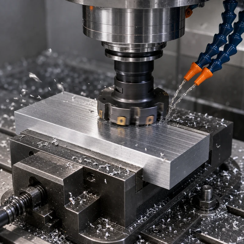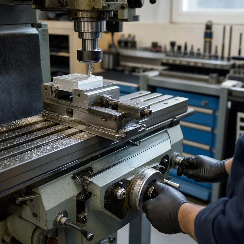
Manual milling remains valuable wherever a machinist needs direct control, quick setup, and immediate feedback. A skilled operator moves the table and spindle with handwheels or power feeds, reads the cut, and adjusts the process without first building a complete CNC program.
It is not a primitive substitute for automation. Used for the right work, a manual mill can be the fastest route to a repair, prototype, fixture detail, or one-off feature. The tradeoff is that repeatability and productivity depend heavily on the operator and the measuring plan.
What Is Manual Milling?
Manual milling removes material with a rotating multi-edge cutter while the operator controls motion along the machine axes. Most shop machines are vertical knee mills, although horizontal mills and bed-type machines are also used. The work is secured in a vise, on a fixture plate, or directly to the table.
| Element | Manual milling approach | Engineering implication |
|---|---|---|
| Motion control | Handwheels, levers, stops, and optional power feed | Fast intervention but operator-dependent |
| Position reference | Dials, digital readout, edge finder, indicators | Requires deliberate datum control |
| Tool path | Planned and executed by the machinist | Ideal for simple, visible features |
| Repeatability | Relies on setup, stops, and technique | Best for low quantities |
| Change response | Immediate at the machine | Useful in development and repair |
Core Machine Components
- Spindle and head: hold and rotate the cutter; many vertical mills allow speed changes and head positioning.
- Table and saddle: provide longitudinal and cross travel.
- Knee or quill: supplies vertical positioning and controlled drilling or boring motion.
- Vise and fixtures: locate the work while resisting cutting forces.
- Digital readout: displays axis position and reduces dependence on dial counting.
A Practical Manual Milling Workflow
- Review the drawing. Identify datums, stock allowance, critical features, surface finish, and inspection points.
- Plan the setup. Choose stable reference faces and keep the work supported without obstructing tool access.
- Prepare stock. Saw oversize, remove burrs, and establish clean locating surfaces.
- Align the work. Indicate the vise or part, find an edge, and establish the coordinate origin.
- Select tooling and speed. Match cutter geometry, diameter, speed, feed, and coolant to the material.
- Rough then finish. Leave a controlled allowance before the final pass.
- Inspect in stages. Verify datums and critical dimensions before removing the setup.
Common Operations
Manual mills handle facing, slotting, side milling, drilling, countersinking, reaming, boring, chamfering, and simple contour work. An edge finder and digital readout make hole patterns practical, while a rotary table or dividing head extends the machine to arcs and indexed features.
Where Manual Milling Works Best
- Repairing a damaged surface, keyway, or mounting pattern
- Producing a single fixture bracket, soft jaw, stop, or gauge component
- Making simple prototypes while dimensions are still changing
- Adding a secondary feature to an existing part
- Training machinists to understand chip formation, workholding, and datum control
Manual Milling vs CNC Milling
| Decision factor | Manual mill | CNC mill |
|---|---|---|
| Quantity | One-off and very small batches | Repeated batches and production |
| Geometry | Simple, open, operator-visible features | Complex contours and coordinated motion |
| Setup investment | Low programming overhead | Programming, simulation, and proving required |
| Cycle consistency | Varies with operator | Highly repeatable after prove-out |
| Design changes | Very quick for simple edits | Program and documentation update |
| In-process attention | Continuous operator involvement | More automated once stable |
Complex profiles, tight positional relationships, and repeated production generally favor CNC milling services. Manual work can still support CNC production by preparing fixtures, modifying soft jaws, or rescuing a simple urgent feature.
Accuracy and Surface Finish
A well-maintained machine in skilled hands can produce precise work, but capability must be proven rather than assumed. Backlash, spindle condition, table wear, thermal drift, tool deflection, and clamping force all matter. Approach critical coordinates consistently, use a finish allowance, and inspect from the same datums defined on the drawing.
Surface finish depends on cutter sharpness, spindle runout, tram, feed uniformity, rigidity, and chip evacuation. A power feed can improve consistency on long finishing passes.
Design and Quoting Guidance
Keep internal corners compatible with standard cutters, provide tool access, avoid unnecessarily deep narrow pockets, and specify tolerances only where function requires them. For a sourcing decision, compare total setup and inspection time rather than machine hourly rate alone. MTSPi can review the model through its machining service workflow and align requirements with its quality assurance process.
Frequently Asked Questions
Is manual milling obsolete?
No. It remains efficient for repairs, tooling, simple prototypes, and low-volume work.
Can a manual mill hold tight tolerances?
Yes within a verified process window, but the machine condition, operator, setup, measurement method, and part geometry determine the result.
When should a job move to CNC?
Move when coordinated geometry, repeat quantity, cycle consistency, or traceable process control outweighs programming and prove-out time.
Conclusion
Manual milling is strongest when adaptability matters more than automation. A sound datum plan, rigid setup, suitable cutter, staged inspection, and experienced operator turn it into a precise and economical production tool for the right scope.