Categories
Blog Quality & Tolerances

Injection Molding Bubbles and Voids: An Evidence-Led Troubleshooting Guide

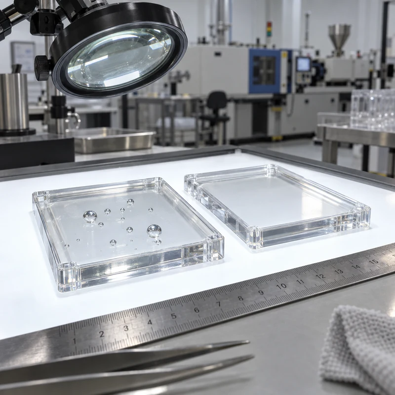
An apparent bubble in an injection-molded part may be a gas pocket or a shrinkage void. Identify the mechanism before changing the process. Gas-related defects can involve moisture, entrained air, or degradation. A shrinkage void forms when internal contraction is not adequately supplied with material during solidification. The same visual description does not justify the same correction.

Preserve Evidence Before Adjusting Settings

Retain defective and acceptable samples, identify the cavity, and record the material lot, startup condition, and current settings. Photograph the location relative to the gate and thick sections. Note whether the defect is repeatable in one location or scattered across the part.

Transparent parts make internal defects easier to see, but a sound-looking exterior does not rule out an internal void. Where the application warrants it, use an approved inspection method such as controlled sectioning or suitable imaging. Do not heat unknown plastics with an open flame as an informal diagnostic test.

Observation Useful investigation What it does not prove alone
Pocket in the center of a thick section Packing effectiveness and cooling-related shrinkage That moisture can be ruled out without other evidence
Scattered pockets with surface streaking Resin condition, moisture, contamination, and melt history That drying is the only cause
Defect near a flow-ending region Fill pattern and vent condition That a higher injection speed will solve it
Problem after a prolonged machine interruption Residence time and material degradation That every subsequent shot is acceptable

BASF’s troubleshooting guidance distinguishes gas bubbles from voids and notes the connection between voids and thick, internally molten regions. Use such guidance as a diagnostic starting point, not a replacement for examining the actual part.

Check Resin Condition at the Point of Use

For moisture-sensitive grades, verify the material supplier’s drying requirements and the condition of material entering the machine. A dryer temperature display does not confirm the pellets have reached an acceptable moisture level. Review residence time in the dryer, loading practice, and exposure during transfer.

Keep resin grade, colorant, additives, and regrind proportion identifiable. If the defect appeared after a material change, retain samples from both conditions and check whether the change was approved. Drying an unfamiliar mixture more aggressively is not a substitute for establishing what material is being processed.

Review the Melt and Filling History

Inspect the approved processing window against actual operating conditions. Barrel settings, measured melt behavior, recovery conditions, and residence time must be considered together. A machine idle period or an unsuitable shot-to-barrel relationship can change the thermal history even when the temperature setpoints remain unchanged.

Air management also deserves a targeted review. Examine the filling sequence, vent condition, and melt preparation with the process engineer. Raising temperature or changing injection speed without identifying the mechanism may move the defect or introduce another one. The melt-temperature and material guide explains why processing advice must be grade-specific.

Document one controlled adjustment at a time when isolating a cause. Where variables interact, use an agreed experimental plan rather than informal simultaneous changes. Keep machine operation and mold intervention within trained personnel’s procedures.

Test Whether Packing Can Feed the Critical Region

If evidence indicates a shrinkage void, review whether the flow path remains capable of supplying the region during packing. A holding-pressure increase cannot compensate indefinitely for a gate that has already frozen. It can also create flash, residual stress, or dimensional changes elsewhere.

A qualified process study may examine part-weight response to hold time together with gate behavior and defect incidence. Record the stable process conditions and use the material supplier’s limits. Do not treat a single heavier part as proof that the internal defect has disappeared.

Address Geometry When the Process Window Is Too Narrow

Thick regions cool and shrink differently from adjacent thin sections. Protolabs’ moldability guidance identifies thick sections as a risk for sink and void formation. Evaluate whether a heavy boss or local mass can be cored while preserving its structural function. Review wall transitions, gate location, and the ability to feed the affected region with the tooling specialist.

Consider a hypothetical mounting boss attached to a thin housing wall. If the pocket repeatedly appears inside the boss, making the entire surrounding wall thicker may add material and create additional cooling problems. A revised boss and rib arrangement may be worth evaluating instead. That decision requires a new structural and molding review, not just a cosmetic repair.

Any machining of samples for diagnosis should preserve the defect evidence and sample identity. A machined prototype can help assess fit, but it cannot prove the molding process is free of internal voids.

Verify the Correction Beyond the First Good Shot

Define success before running the confirmation lot. Check the internal defect with the chosen method and verify that the correction has not created flash, sink, warpage, unacceptable dimensions, or a new cosmetic issue. Include all relevant cavities and agreed operating conditions.

  • Compare samples against the original defect map.
  • Record the final approved process and material condition.
  • Repeat the critical functional and dimensional checks.
  • Assess startup or interruption conditions where relevant.
  • Establish lot disposition and a reaction plan if the defect returns.

When requesting help with mechanical interfaces or prototype components, send MTSPi the drawing, defect photographs, and acceptance criteria through the technical inquiry page. Keep the molding-process investigation with the responsible molder and material specialists.

Frequently Asked Questions

Will increasing pressure always remove bubbles?

No. Gas pockets and shrinkage voids have different mechanisms, and pressure changes may introduce other defects. Diagnose first.

Are internal bubbles only a cosmetic issue?

No. Depending on location and application, internal defects can affect strength, sealing, or durability even if the surface looks acceptable.

Should every resin receive the same drying cycle?

No. Use the specific grade supplier’s requirements and verify the condition of material at the machine.

Does one clear sample prove the fix?

No. Confirm the agreed batch, cavity coverage, inspection method, and process conditions before releasing production.

Technical reference basis: BASF Injection Molding Troubleshooter and engineering-thermoplastic defect guidance; Protolabs moldability guidance on thick sections. Diagnostic examples are illustrative and do not replace resin-specific processing instructions.

Categories
Blog CNC Materials Manufacturing Process Comparisons Quality & Tolerances

Injection Molding Melt Temperature Guide: Materials, Settings, and Defect Control

Injection molding melt temperature controls viscosity, cavity filling, weld lines, surface replication, shrinkage, molecular orientation, and degradation. It is related to barrel-zone settings but is not identical to the displayed heater temperatures.

The correct range depends on polymer grade, additives, moisture, residence time, shear, screw design, machine size, part geometry, and mold temperature. Material supplier data is the starting point, followed by an approved process window.

Quick Answer

Use the resin manufacturer’s grade-specific range, dry the material correctly, measure actual melt when needed, and establish a stable window rather than one nominal number. Change temperature only after considering speed, pressure, back pressure, residence time, and mold conditions.

Comparison at a Glance

Factor Option A Option B
Low melt temperature High viscosity, short shots, weak weld lines Increase within approved window and verify drying
High melt temperature Degradation, gas, discoloration, flash Reduce heat or residence and check shear
Barrel display Shows zone control, not actual melt Verify with purge measurement or validated method
Shear heating Raises polymer temperature during plasticizing and fill Control screw speed and injection speed
Residence time Long exposure can damage resin Match shot size and cycle to machine capacity

Melt Temperature vs Barrel Temperature

Heater bands control barrel zones while the rotating screw generates shear heat. The polymer experiences a thermal history, so actual melt can differ from setpoints. Measure consistently and safely when troubleshooting.

Material Families

Amorphous and semi-crystalline polymers respond differently. ABS, PC, PMMA, PA, POM, PP, PE, PBT, and PEEK each need grade-specific conditions. Filled, flame-retardant, recycled, colored, and medical grades may use different limits.

Drying and Moisture

Hygroscopic materials can hydrolyze at processing temperature, reducing molecular weight and strength even if the part looks acceptable. Confirm dryer temperature, dew point, time, airflow, and material handling.

Defects Linked to Temperature

Low temperature can cause short shots, hesitation, poor knit lines, dull surfaces, and high pressure. Excessive temperature can cause splay, gas, odor, discoloration, flash, sticking, or brittleness. Similar defects can also come from moisture, venting, speed, or mold temperature.

  • Avoid changing several variables at once
  • Record actual conditions and lot
  • Check purge appearance and odor
  • Review residence time and shot utilization
  • Use a structured process study

Building a Process Window

Establish acceptable low and high boundaries for melt, fill speed, pack, cooling, and mold temperature. Validate critical dimensions and appearance across normal variation.

Design and Tooling Interaction

Thin walls, long flow paths, small gates, abrupt thickness changes, weak venting, and poor cooling may force an unnecessarily narrow thermal window. Improve part and mold design instead of relying on hotter material to solve every fill problem.

Quality Documentation

Record resin grade, lot, regrind policy, drying, machine, screw, zone settings, cycle, measured melt, mold temperature, pressure, and inspection results for controlled production.

Frequently Asked Questions

Is melt temperature the same as nozzle temperature?

No. Nozzle temperature is one setpoint; actual melt reflects barrel heating, shear, residence, and heat loss.

Should I use a universal temperature chart?

Charts provide orientation only. Use the exact resin supplier data and validate the process on the actual machine, mold, and part.

What happens if nylon is wet?

Moisture can create splay and hydrolytic degradation during melting, reducing strength. Proper drying and handling are essential.

Related MTSPi Resources

Categories
Blog Manufacturing Process Comparisons Quality & Tolerances

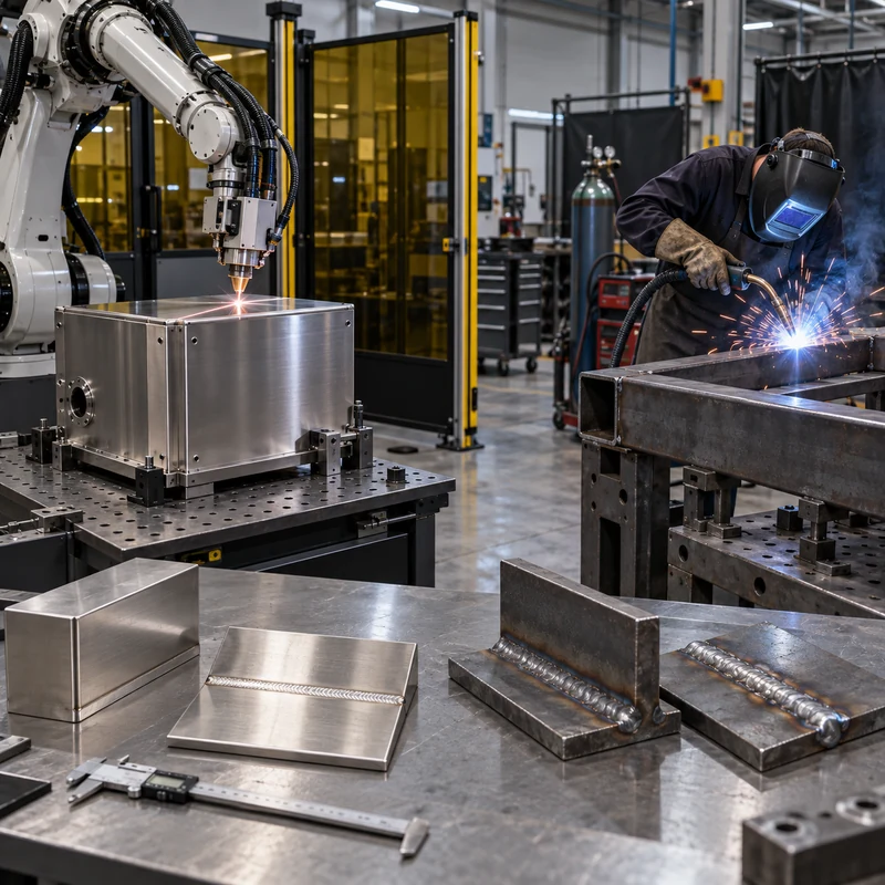
Laser Welding vs MIG Welding: Differences, Applications, and Design Rules

Laser welding and MIG welding can both create strong production joints, but they differ in energy concentration, fit-up tolerance, speed, automation, filler use, heat input, and equipment cost. The right process starts with the joint and production system, not a headline about speed.

This comparison focuses on practical design, quoting, distortion, and inspection for fabricated and machined assemblies.

Quick Answer

Choose laser welding for precise repeatable joints, low heat input, limited distortion, and automated sheet-metal production with excellent fit-up. Choose MIG for versatile structural fabrication, thicker sections, larger gaps, repairability, and lower equipment barriers.

Comparison at a Glance

Factor Option A Option B
Heat source Concentrated laser beam Electric arc with wire electrode
Fit-up Requires tight consistent joints More tolerant of gaps with filler
Speed Very high in automated cells Productive but generally slower
Distortion Often lower due to focused heat Higher heat input can increase movement
Investment High equipment and safety cost Lower and widely available

Process Fundamentals

Laser welding focuses optical energy into a small zone and may operate with or without filler. MIG continuously feeds consumable wire through a shielding-gas torch, making filler addition part of the process.

Joint Design and Fit-Up

Laser joints need consistent gap, edge position, focus, and cleanliness. MIG can bridge more variation but still needs suitable preparation, access, and control.

  • Define joint gap and edge condition
  • Provide fixture and clamp access
  • Avoid hidden reflections for laser cells
  • Plan torch angle and stickout for MIG
  • Control coatings and contamination

Materials and Thickness

Both methods can join steels, stainless, and selected aluminum alloys. Reflective materials, coatings, dissimilar combinations, and crack-sensitive alloys require process development. Thick sections may need multi-pass MIG or hybrid strategies.

Distortion and CNC Interfaces

Laser welding often protects nearby precision features through lower heat input, but fixtures and sequence still matter. MIG assemblies may require post-weld machining of datums, bores, and sealing faces.

Production Economics

Laser systems cost more but can deliver rapid automated cycles and low finishing labor at volume. MIG equipment is accessible and flexible for mixed fabrication. Calculate fixture, programming, filler, gas, cleanup, inspection, and rework.

Inspection and Quality

Visual inspection, dimensional checks, cross-sections, leak testing, penetrant, radiography, or other NDT may be appropriate. Acceptance criteria should match joint consequence.

  • Approve weld procedure and samples
  • Monitor penetration and porosity
  • Check distortion against final datums
  • Trace parameters for critical programs

Frequently Asked Questions

Is laser welding stronger than MIG?

Strength depends on joint design, penetration, material, defects, and procedure. Either can meet demanding requirements when correctly engineered.

Does laser welding need filler wire?

Not always. Autogenous laser welding is common, but filler may help metallurgy, gap bridging, or reinforcement.

Which process is cheaper?

MIG is usually cheaper to start. Laser can lower unit cost in repeatable automated production where speed and reduced finishing offset capital cost.

Related MTSPi Resources

Categories
Blog Design, Cost & Sourcing Manufacturing Process Comparisons Quality & Tolerances

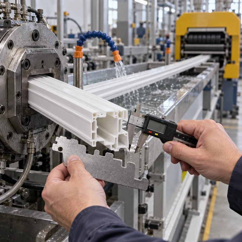
Plastic Extrusion Design Guide: Tolerance Control, Materials, and Profile Quality

Plastic extrusion continuously pushes molten polymer through a shaped die, then cools and pulls the profile to size. The process is efficient for rails, seals, channels, tubes, trim, and structural profiles, but dimensional control depends on much more than the die opening.

A profile can leave the die near nominal and still twist, bow, shrink, or change wall thickness during cooling and pulling. This guide connects geometry, material, tooling, process settings, inspection, and downstream CNC work.

Quick Answer

Use balanced walls, generous transitions, realistic tolerances, and datums that can be measured consistently. Control melt temperature, output, cooling, puller speed, and material condition together. Prototype the cross-section before committing to long production runs.

Key Engineering Factors

Factor Practical effect Control method
Wall variation Uneven flow and cooling create distortion Keep thickness transitions gradual
Die swell Profile expands after leaving the die Compensate through tooling and stable process settings
Cooling Uneven shrink creates bow and twist Balance water, air, support, and line speed
Puller speed Changes section size and residual stress Monitor speed against output rate
Material lot Viscosity and shrinkage can vary Use controlled resin specifications and incoming checks

How Extrusion Tolerances Are Created

The finished dimension results from die geometry, melt rheology, pressure, drawdown, cooling shrinkage, calibration, haul-off speed, and residual stress. Tightening a drawing tolerance without changing the process does not create capability.

Cross-Section Design Rules

Balanced geometry promotes even flow and cooling. Thick masses cool slowly while thin walls freeze early, producing stress and distortion. Hollow chambers need webs and radii that allow material to divide and reunite without weak lines.

  • Keep nominal walls as uniform as function allows
  • Avoid abrupt heavy-to-thin transitions
  • Use radii instead of sharp internal corners
  • Provide enough support for thin fins and lips
  • Discuss hollow chambers and weld lines with the die maker

Datum and Tolerance Strategy

Dimension the profile from stable, functional surfaces. Do not chain every cross-section dimension when one datum scheme can control assembly. Separate critical fit dimensions from cosmetic or non-functional geometry.

  • Use profile or contour tolerances where appropriate
  • Specify bow and twist over a defined length
  • State measurement temperature and conditioning
  • Identify cut-length and end-squareness separately

Materials and Shrinkage

PVC, ABS, polycarbonate, polyethylene, polypropylene, nylon, TPE, and filled compounds behave differently. Fillers can reduce shrinkage but change surface, wear, and flow. Hygroscopic polymers require drying.

Cooling, Calibration, and Cutoff

Vacuum calibration can hold demanding external surfaces. Water temperature, spray distribution, support rollers, and puller alignment influence straightness. Cutoff adds length variation, burrs, and end deformation.

Inspection and Process Capability

Use gauges or optical systems for recurring cross-sections, and confirm results after the profile reaches stable temperature. Capability should be demonstrated over time, not inferred from one first sample.

  • Measure multiple positions across the run
  • Track key dimensions with process settings
  • Inspect bow, twist, surface, color, and cut ends
  • Retain approved samples and gauge methods

When CNC Secondary Operations Help

Drilling, milling, routing, tapping, and end machining can add accurate interfaces after extrusion. Fixtures must support the profile without crushing it, and datums should match the final assembly.

Frequently Asked Questions

What is a realistic extrusion tolerance?

It depends on material, section size, geometry, calibration, and measurement length. Ask the supplier for demonstrated capability on comparable profiles.

Why do extrusions twist?

Asymmetric walls, uneven cooling, off-center pull, residual stress, and material variation can all create twist.

Can extruded plastic be CNC machined?

Yes. CNC operations are common for holes, slots, pockets, threads, and precision ends when the part is supported correctly.

Related MTSPi CNC Resources

Categories
Blog Design, Cost & Sourcing Quality & Tolerances

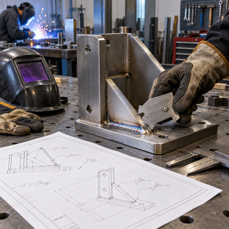
Welding Symbols Explained: Meaning, Types, and Drawing Notes for Machined Assemblies

Welding symbols turn an assembly requirement into a compact manufacturing instruction. A few lines and numbers can define the joint, weld type, side, size, length, spacing, contour, finish, and whether the operation happens in the shop or in the field. That compression is useful, but it also means one missed mark can change cost, distortion, accessibility, and inspection.

This guide explains the notation from the viewpoint of designers and buyers of machined assemblies. It focuses on how weld callouts interact with CNC datums, post-weld machining, sealing surfaces, and quotation risk.

Quick Answer: How Do You Read a Welding Symbol?

Follow the same sequence every time: trace the arrow to the joint, identify the governing standard, check which side of the reference line contains the basic symbol, read size information on the left, read length and pitch on the right, then inspect the arrow-reference junction and contour marks for supplementary requirements.

Anatomy of a Welding Symbol

The arrow points to the physical joint. The horizontal reference line carries the weld information. An optional tail can identify the welding process, procedure, specification, or drawing note. A circle at the arrow junction generally indicates an all-around weld, while a flag indicates a field weld.

On drawings that follow AWS conventions, a symbol below the reference line applies to the arrow side and a symbol above applies to the other side. Symbols on both sides call for welding on both faces. ISO drawings can use different reference-line logic, so the title block or general notes must state the standard.

Common Weld Types and Their Uses

Weld type Typical symbol form Common application Machining implication
Fillet Triangle T-joints, lap joints, brackets Heat can pull machined faces out of position
Square groove Parallel edges Thin butt joints Edge squareness and root gap affect penetration
V or bevel groove Angled groove Thicker structural joints Preparation may be milled before welding
U or J groove Curved preparation Heavy sections with controlled filler volume Usually needs dedicated edge preparation
Plug or slot Hole or slot notation Joining overlapping plates Hole location and fit influence load transfer
Spot or seam Resistance-weld notation Sheet-metal enclosures Access and electrode clearance must be designed

How Fillet Weld Dimensions Work

The dimension to the left of a fillet symbol normally controls weld size. Information to the right controls weld length and, for intermittent welds, pitch. A continuous weld may have no length value. When welds appear on both sides, the symbols indicate whether the pattern is aligned or staggered.

Oversizing a fillet does not automatically improve an assembly. It adds heat, filler, time, and distortion. Specify the size required by the load and code, then decide whether intermittent welding can reduce heat without compromising fatigue, sealing, corrosion, or stiffness.

Groove Welds, Root Opening, and Penetration

Groove callouts describe both the weld and the edge preparation. The drawing may identify preparation depth, root opening, groove angle, backing, and complete or partial joint penetration. These details strongly affect labor because deeper preparation requires more cutting, filler, passes, cleaning, and inspection.

For a welded component that will be finish machined, leave enough material around the joint and critical surfaces. The machining allowance must cover predictable distortion without making the section unnecessarily heavy.

Contour and Finish Symbols

Flush, convex, and concave contour marks define the required weld profile. A letter may define the finishing method, such as grinding or machining. A flush requirement should be tied to function: bearing clearance, sealing, cosmetic appearance, or interference avoidance. Applying it everywhere can add substantial cost without improving performance.

AWS and ISO Welding Symbols

Topic AWS-style drawing ISO-style drawing
Reference line Usually one line May use a solid and dashed line
Side indication Above or below the line Depends on the selected ISO system
Fillet size Commonly leg size May identify throat or leg with a prefix
Units Often inches on US drawings Commonly millimetres
Best practice State AWS edition State ISO edition and system

Designing Machined Parts for Welding

  • Separate locating datums from heat-affected areas whenever possible.
  • Add tabs, slots, shoulders, or pilot features to make fixture positioning repeatable.
  • Provide torch access and space for clamps, backing, and inspection tools.
  • Machine sealing faces, precision bores, and bearing seats after welding when distortion cannot be tolerated.
  • Define whether dimensions apply before or after welding and finishing.
  • Use a realistic datum scheme for post-weld inspection rather than relying on free-state dimensions alone.

Weld Inspection Checklist

Inspection should match the consequence of failure. Visual checks can verify location, continuity, contour, undercut, porosity, and obvious cracking. Dimensional inspection checks distortion and feature position. Dye penetrant, magnetic particle, ultrasonic, or radiographic methods may be required for critical joints, but the drawing should identify the acceptance standard instead of leaving the shop to guess.

Common Drawing Errors

  • Mixing AWS and ISO conventions on one drawing.
  • Calling out a full-length weld when intermittent welding was intended.
  • Omitting the governing standard, units, or weld procedure reference.
  • Placing a weld where a tool, torch, or inspection probe cannot reach.
  • Requiring a ground-flush contour without identifying which surface controls function.
  • Dimensioning precision holes before welding with no allowance for post-weld correction.

Frequently Asked Questions

What does a circle at the arrow junction mean?

It normally calls for welding around the complete perimeter of the indicated joint. Confirm the governing standard and ensure every segment is physically accessible.

What is the difference between arrow side and other side?

The arrow side is the face indicated by the arrow. The other side is the opposite face. The symbol position maps the requirement to one or both faces according to the drawing standard.

Should precision features be machined before or after welding?

Rough machining can occur before welding, but tight bores, flat sealing faces, and positional features are often finished afterward so the machining operation removes weld-induced distortion.

Related MTSPi CNC Resources

Categories
Blog Manufacturing Process Comparisons Quality & Tolerances

Precision Metal Stamping: What Determines Part Accuracy and When CNC Is Better

Precision Metal Stamping: What Determines Part Accuracy and When CNC Is Better is a practical manufacturing question because the answer affects cost, lead time, material behavior, inspection, and the path from prototype to production. For MTSPi CNC customers, the key is not simply naming a process, but understanding how the process connects with machined parts, fixtures, tolerances, surface requirements, and final assembly.

This guide explains precision metal stamping from an engineering and purchasing point of view. It is written for product developers, mechanical engineers, sourcing teams, and buyers who need clear decisions rather than generic process descriptions.

Quick Answer

Stamping is ideal for high-volume sheet metal parts with repeatable 2D or formed features. CNC machining is better when quantities are low, geometry is thicker or more complex, tolerances are very tight, or the design is still changing.

Key Differences at a Glance

Point Option A Option B
Best volume Medium to high volume Prototype to low-volume precision batches
Tooling Dedicated die required Soft tooling and fixtures
Geometry Sheet metal cuts and forms 3D shapes, pockets, bores, threads
Design changes Can be expensive after hard tooling Easier to revise
Accuracy drivers Die wear, springback, material thickness Machine rigidity, toolpath, setup, inspection

How the Process Choice Affects Real Parts

A manufacturing method should be selected around the feature that actually controls function. Cosmetic surfaces, hidden support features, threads, bores, sealing faces, heat-transfer areas, and assembly datums do not carry the same risk. When those requirements are mixed together without priority, quotes become inconsistent and production becomes harder to control.

The safest workflow is to define the part requirement first, then match the process. A printed prototype may answer shape questions, a molded sample may answer appearance questions, and a CNC machined sample may answer tolerance, material, and functional questions. Many successful projects use more than one method before the final design is locked.

Design and Manufacturing Considerations

  • Use generous bend radii where possible to reduce cracking and springback variation.
  • Keep holes away from bends unless the tooling plan supports them.
  • Define burr direction when assembly or safety is affected.
  • Prototype critical interfaces with CNC or soft tooling before hard dies.
  • Do not choose stamping only because the final volume is uncertain.

Cost, Lead Time, and Risk Factors

Cost is driven by setup, tooling, material, machine time, inspection, finishing, and revision risk. A low unit price is not always the lowest project cost if it creates rework later. For prototypes and low-volume orders, flexibility can be more valuable than a process with a lower theoretical unit cost.

  • Use standard materials and standard feature sizes when they do not weaken the design.
  • Separate critical tolerances from general dimensions so the supplier knows where to focus.
  • Confirm surface finish and cosmetic requirements before production begins.
  • Avoid late changes to mounting holes, connector openings, datum faces, and threaded features.
  • Send CAD files and 2D drawings together when tolerances, threads, or finishes matter.

Quality Checks Before Production

A good quality plan checks the features that influence assembly and performance. Depending on the part, this may include dimensional inspection, thread gauges, surface roughness, flatness, perpendicularity, burr control, coating thickness, visual appearance, and fit with mating parts.

When This Topic Matters for CNC Buyers

precision metal stamping matters when a team is comparing prototype routes, validating a design, replacing a weak supplier, or trying to reduce manufacturing cost without damaging function. The best choice is usually the process that answers the current engineering question with the least unnecessary risk.

MTSPi CNC Engineering Notes

MTSPi CNC supports precision CNC milling, turning, rapid prototyping, low-volume production, finishing, and inspection for custom parts. If your project uses molding, casting, welding, PCB assemblies, or 3D printing, CNC machining can still be important for datums, holes, threads, sealing faces, fixtures, and production-ready prototypes.

Frequently Asked Questions

Can this process replace CNC machining?

Sometimes it can replace CNC for non-critical geometry, but CNC is often still needed when tight tolerances, real engineering material, threads, flat sealing faces, or precise mating features are required.

What files help MTSPi CNC review a project?

STEP or STP files are useful for geometry. A 2D drawing is important for tolerances, materials, threads, surface finish, inspection requirements, and notes that are not obvious from the CAD model.

How do I reduce manufacturing risk?

Define critical features, avoid unnecessary tight tolerances, confirm material and finish requirements, and use prototypes to validate assembly before committing to higher-volume tooling or production.

Related MTSPi Resources

Categories
Blog Manufacturing Process Comparisons Quality & Tolerances

Cleanroom Injection Molding vs Standard Molding: Key Differences for Precision Parts

Cleanroom Injection Molding vs Standard Molding: Key Differences for Precision Parts is a practical manufacturing question because the answer affects cost, lead time, material behavior, inspection, and the path from prototype to production. For MTSPi CNC customers, the key is not simply naming a process, but understanding how the process connects with machined parts, fixtures, tolerances, surface requirements, and final assembly.

This guide explains cleanroom injection molding vs standard molding from an engineering and purchasing point of view. It is written for product developers, mechanical engineers, sourcing teams, and buyers who need clear decisions rather than generic process descriptions.

Quick Answer

Use standard molding for general industrial, consumer, and enclosure components where normal factory cleanliness is acceptable. Use cleanroom molding when particle contamination, biological burden, optical clarity, or medical validation can affect product performance.

Key Differences at a Glance

Point Option A Option B
Environment Controlled air and particle limits Normal manufacturing environment
Parts Medical, diagnostic, optical, sensitive electronics Industrial covers, brackets, caps, housings
Documentation Higher traceability and validation records Standard production records
Cost Higher operating and monitoring cost Lower cost for ordinary parts
Risk focus Contamination, packaging, handling Dimensions, cycle stability, cosmetic quality

How the Process Choice Affects Real Parts

A manufacturing method should be selected around the feature that actually controls function. Cosmetic surfaces, hidden support features, threads, bores, sealing faces, heat-transfer areas, and assembly datums do not carry the same risk. When those requirements are mixed together without priority, quotes become inconsistent and production becomes harder to control.

The safest workflow is to define the part requirement first, then match the process. A printed prototype may answer shape questions, a molded sample may answer appearance questions, and a CNC machined sample may answer tolerance, material, and functional questions. Many successful projects use more than one method before the final design is locked.

Design and Manufacturing Considerations

  • Specify cleanliness requirements only when they are functional or regulatory needs.
  • Separate cosmetic requirements from contamination requirements on the drawing.
  • Confirm resin compatibility with sterilization, cleaning agents, and final assembly conditions.
  • Plan inspection for critical dimensions, flash, particulates, and packaging damage.
  • Coordinate CNC inserts, machined fixtures, or threaded metal parts before mold validation.

Cost, Lead Time, and Risk Factors

Cost is driven by setup, tooling, material, machine time, inspection, finishing, and revision risk. A low unit price is not always the lowest project cost if it creates rework later. For prototypes and low-volume orders, flexibility can be more valuable than a process with a lower theoretical unit cost.

  • Use standard materials and standard feature sizes when they do not weaken the design.
  • Separate critical tolerances from general dimensions so the supplier knows where to focus.
  • Confirm surface finish and cosmetic requirements before production begins.
  • Avoid late changes to mounting holes, connector openings, datum faces, and threaded features.
  • Send CAD files and 2D drawings together when tolerances, threads, or finishes matter.

Quality Checks Before Production

A good quality plan checks the features that influence assembly and performance. Depending on the part, this may include dimensional inspection, thread gauges, surface roughness, flatness, perpendicularity, burr control, coating thickness, visual appearance, and fit with mating parts.

When This Topic Matters for CNC Buyers

cleanroom injection molding vs standard molding matters when a team is comparing prototype routes, validating a design, replacing a weak supplier, or trying to reduce manufacturing cost without damaging function. The best choice is usually the process that answers the current engineering question with the least unnecessary risk.

MTSPi CNC Engineering Notes

MTSPi CNC supports precision CNC milling, turning, rapid prototyping, low-volume production, finishing, and inspection for custom parts. If your project uses molding, casting, welding, PCB assemblies, or 3D printing, CNC machining can still be important for datums, holes, threads, sealing faces, fixtures, and production-ready prototypes.

Frequently Asked Questions

Can this process replace CNC machining?

Sometimes it can replace CNC for non-critical geometry, but CNC is often still needed when tight tolerances, real engineering material, threads, flat sealing faces, or precise mating features are required.

What files help MTSPi CNC review a project?

STEP or STP files are useful for geometry. A 2D drawing is important for tolerances, materials, threads, surface finish, inspection requirements, and notes that are not obvious from the CAD model.

How do I reduce manufacturing risk?

Define critical features, avoid unnecessary tight tolerances, confirm material and finish requirements, and use prototypes to validate assembly before committing to higher-volume tooling or production.

Related MTSPi Resources

Categories
Blog CNC Materials Quality & Tolerances

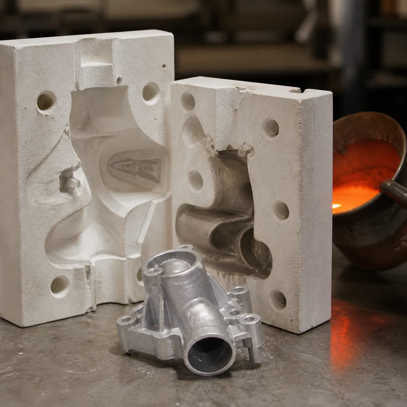
Plaster Mold Casting: Process, Materials, Design, and Machining

Plaster mold casting is a precision casting route for nonferrous metal parts that need smoother surfaces and finer details than ordinary sand casting typically provides. The process uses a disposable gypsum-based mold formed around a reusable pattern, then dried and filled with molten alloy.

It can reduce machining on housings, covers, impellers, and decorative or low-volume engineering components. Its limitations—slow mold preparation, moisture control, fragile molds, and restricted alloy temperature—must be considered early.

How Plaster Mold Casting Works

  1. Create the pattern. Patterns may be machined, molded, or additively produced and include draft, shrink allowance, gates, and risers.
  2. Mix the slurry. Gypsum binder, water, and refractory or setting modifiers are blended under controlled conditions.
  3. Pour around the pattern. The fluid mix captures small radii, lettering, and surface texture.
  4. Set and remove the pattern. Mold sections are separated carefully to avoid edge damage.
  5. Dry and bake. Free and chemically held moisture must be driven out before metal enters the cavity.
  6. Assemble and pour. Cores and mold halves are located, supported, and filled with a compatible nonferrous alloy.
  7. Break out and finish. The plaster is removed; gates are cut away and critical features are inspected or machined.

Materials and Alloy Compatibility

Aluminum, magnesium, zinc, and selected copper-base alloys are common candidates. Plaster has limited high-temperature capability and low permeability, so the method is generally unsuitable for steel and other very high-temperature alloys. The exact plaster formulation and firing schedule must match the alloy and section thickness.

Design need Typical response Risk to manage
Fine detail Fluid slurry reproduces pattern detail Pattern defects also reproduce
Smooth surface Fine mold particles reduce texture Handling damage can mark the cavity
Thin walls Possible with balanced filling Misrun and premature freezing
Internal passages Use compatible cores Core location and removal
Dimensional control Stable pattern and drying cycle Mold expansion, shrinkage, distortion

Advantages

  • Better as-cast surface than many conventional sand processes
  • Fine lettering, ribs, bosses, and decorative detail
  • Lower tooling cost than permanent metal molds for modest volume
  • Complex shapes that can reduce assemblies and stock removal
  • Near-net geometry that leaves machining only on functional interfaces

Limitations and Defect Prevention

Moisture and Gas

Residual water can generate gas violently during pouring and cause porosity or surface defects. Drying time, mold thickness, oven loading, and storage humidity require documented control.

Low Permeability

Plaster does not vent as freely as coarse sand. Gating, venting, vacuum assistance where appropriate, and a controlled pour rate help displaced air escape.

Mold Fragility

Thin edges and cores can chip during pattern removal or assembly. Generous handling features and protected storage reduce damage.

Longer Lead Time

Setting and drying add hours or days before pouring. The method rewards stable planning more than urgent high-volume output.

Design Guidelines

  • Use uniform sections and gradual transitions to control feeding and hot spots.
  • Add draft where the pattern must withdraw from a rigid mold section.
  • Round junctions to improve flow and reduce stress concentration.
  • Place gates and risers with solidification direction in mind.
  • Leave machining allowance on sealing faces, bearing bores, threaded holes, and datum pads.
  • Define cosmetic zones separately from functional surfaces.

Plaster Casting Compared with Alternatives

Process Best fit Key tradeoff
Plaster mold casting Detailed nonferrous parts at low to medium volume Slow drying and limited alloy temperature
Sand casting Large parts and broad alloy range Rougher surface and larger allowances
Investment casting Intricate shapes and broad alloy capability Higher process complexity and cost
Permanent mold casting Repeat nonferrous production Higher tooling investment
CNC machining Tight features and billet material properties More stock removal on complex shapes

A hybrid route is common: cast the near-net body, then machine interfaces through CNC machining services. This preserves casting economy while establishing reliable datums, bores, threads, flatness, and sealing finishes.

Inspection and Secondary Machining

Incoming castings should be checked for fill, cracks, inclusions, porosity, warpage, and damaged detail. Dimensional inspection should reference stable casting datums before machining. Depending on service, a plan may include radiography, dye penetrant, pressure testing, chemical certification, or mechanical testing.

Machining setups must accommodate draft and variable as-cast surfaces. Purpose-built nests, probing, and datum pads can prevent excess removal. MTSPi’s quality assurance resources help connect casting acceptance criteria to the final machined drawing.

Frequently Asked Questions

Is plaster mold casting the same as investment casting?

No. Plaster casting normally uses a reusable pattern to create mold sections; investment casting builds a ceramic shell around an expendable pattern.

Can it cast steel?

It is primarily a lower-temperature nonferrous process. Steel temperatures exceed the practical range of conventional plaster molds.

Does a plaster-cast part need machining?

Often yes on precision bores, threads, sealing surfaces, and datum faces, even when the general shape is near net.

Conclusion

Plaster mold casting is a useful bridge between rough sand castings and higher-investment precision routes. Success depends on pattern quality, complete drying, suitable alloy selection, balanced feeding, and a clear plan for final machining and inspection.

Related MTSPi Resources

Categories
Blog CNC Materials Quality & Tolerances

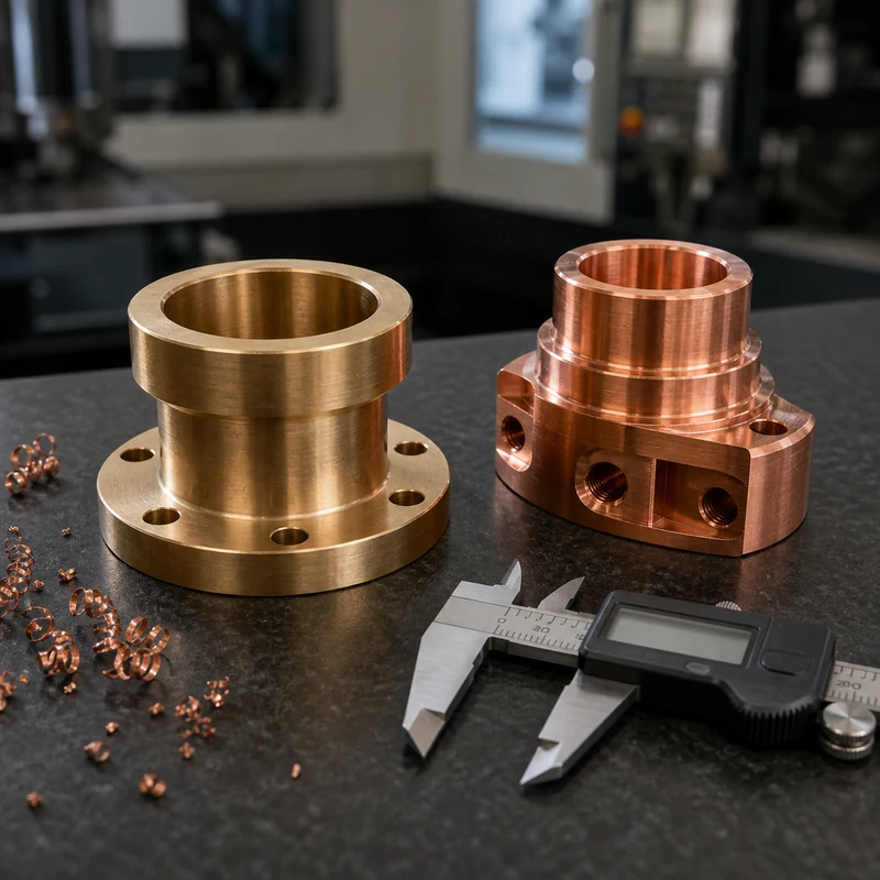
Is Bronze More Expensive Than Copper? CNC Cost Guide

Bronze is not automatically more expensive than copper. The answer changes with alloy grade, stock form, order size, metal-market conditions, and the work required to turn the stock into an inspected part. Commercially pure copper can carry a higher material price than a common bearing bronze, while specialty aluminum-bronze or nickel-bearing grades may cost considerably more.

For a CNC project, price per kilogram is only a starting point. Yield loss, cutting time, tool wear, deburring, inspection, finishing, and service life can outweigh a small difference in raw stock. This guide explains how engineers and buyers can compare copper and bronze on a finished-part basis.

Bronze vs Copper Cost: The Short Answer

Question Copper Bronze
What is it? A base metal; grades range from high-purity copper to alloyed copper A family of copper alloys, commonly containing tin, aluminum, silicon, or nickel
Typical cost position High-purity and oxygen-free grades may command a premium Common grades may be competitive; specialty grades can be costly
Primary value Electrical and thermal conductivity Wear resistance, strength, bearing behavior, or corrosion resistance
Machining cost tendency Ductile grades can produce burrs and difficult chips Many bearing bronzes cut cleanly; tough specialty grades may be slower
Best comparison Exact grade, temper, form, certification, and finished-part quote Exact grade, condition, form, certification, and finished-part quote

There is no reliable universal percentage difference. Commodity prices move, distributors apply different minimums, and a round bar can be priced differently from plate, tube, or a near-net casting of the same nominal alloy. Request quotations using the same quantity, dimensions, certification, and delivery terms.

Why Alloy Grade Changes the Answer

Copper is an element, but industrial copper products still come in many grades. High-conductivity copper, tellurium copper, chromium-zirconium copper, and oxygen-free copper have different performance and supply economics. Bronze is an even broader label: tin bronze, phosphor bronze, aluminum bronze, silicon bronze, and nickel aluminum bronze are not interchangeable.

Alloying additions change strength, hardness, corrosion behavior, casting response, and machinability. Tin, nickel, and other additions also have their own market prices. A material called bronze may therefore be less expensive, similar in price, or more expensive than the copper grade being considered.

Common Copper Choices

  • High-conductivity copper: selected for busbars, electrodes, heat spreaders, and electrical contacts.
  • Oxygen-free copper: used where conductivity, vacuum behavior, or high purity is critical.
  • Free-machining copper alloys: useful when manufacturability must improve without abandoning copper-based performance.
  • Precipitation-hardened copper alloys: selected when greater strength or thermal fatigue resistance is required.

Common Bronze Choices

  • Phosphor bronze: combines strength, fatigue resistance, and useful spring or bearing behavior.
  • Bearing bronze: designed for sliding contact, bushings, thrust washers, and wear components.
  • Aluminum bronze: offers high strength and strong corrosion resistance for demanding mechanical parts.
  • Silicon bronze: valued for corrosion resistance and fabrication characteristics.
  • Nickel aluminum bronze: chosen for severe marine, pump, valve, and high-load applications.

Seven Factors That Drive Finished-Part Cost

1. Current Metal Value

Copper is a globally traded metal, so changes in its market price affect both copper stock and copper-rich bronze. Bronze price also reflects its alloying additions. A quote should have a validity period because a delayed purchase may be exposed to a different surcharge.

2. Stock Form and Availability

Standard bar diameters and plate thicknesses are generally easier to source than an unusual tube, large continuous-cast section, or certified specialty alloy. Minimum order quantities and mill lead time can dominate a prototype order. A designer may reduce cost by choosing a nearby standard size without compromising the final geometry.

3. Buy-to-Fly or Material Yield

A part machined from oversized solid stock can generate far more chips than finished product. Bronze bushings may be economical from hollow bar or near-net cast stock, while a copper heat sink may still require solid plate. Compare the purchased mass, recoverable scrap, and machining allowance—not just finished mass.

4. Machinability

Many pure copper grades are ductile and prone to built-up edge, long chips, smearing, and heavy burrs. Some bearing bronzes machine cleanly and hold stable features, but hard aluminum-bronze and nickel-bearing grades can demand rigid setups and suitable tooling. The exact alloy determines cycle time.

5. Geometry and Tolerances

Deep pockets, slender walls, small internal radii, interrupted cuts, and tight positional tolerances increase setup and inspection effort for either metal. Blanket tolerances can create cost without adding function. Mark the truly critical interfaces and use practical tolerances elsewhere.

6. Finishing and Quality Requirements

Polishing, plating, passivation-like cleaning specifications, conductivity testing, material traceability, first-article inspection, and dimensional reports all affect the quote. Requirements should be stated at RFQ stage so suppliers compare the same scope.

7. Quantity and Supply Risk

Setup cost matters more for one prototype than for a production batch. Conversely, a high-volume program needs stable mill supply and alloy traceability. A nominally cheaper specialty alloy can become expensive if it is available from only one source or requires a large minimum buy.

CNC Machining Copper and Bronze

Manufacturing issue Copper planning Bronze planning
Chip control Use sharp positive tools and prevent built-up edge Confirm grade; many cut cleanly, while high-strength grades need robust tooling
Burr formation Expect careful edge control on ductile grades Often more manageable, but geometry and grade still matter
Heat Conducts heat rapidly; manage distortion and tool interface Lower conductivity than pure copper; monitor localized heat
Workholding Avoid marking soft conductive surfaces Support cast or hollow stock and control clamping distortion
Inspection Define flatness, conductivity, and cosmetic surfaces Define bearing fits, surface finish, and alloy certification
Cost lever Select a machinable grade when conductivity allows Match strength and corrosion performance without overspecifying alloy

Successful CNC machining begins with an exact material callout. A drawing that says only “copper” or “bronze” invites substitutions and inconsistent quotations. Include the UNS or recognized alloy designation, temper or condition, stock form, and permitted equivalents.

When Copper Is the Better Economic Choice

Copper is usually justified when electrical or thermal performance is central to the design. Busbars, electrodes, power contacts, induction components, and heat-transfer parts can lose their purpose if replaced with a lower-conductivity alloy. Paying more for copper may eliminate extra mass, reduce resistance, or improve heat flow.

Do not automatically specify the highest-purity grade. If a moderately alloyed copper meets conductivity requirements and machines faster, it may lower the completed-part price. Review the balance through MTSPi’s copper CNC machining capability and validate any material change with functional testing.

When Bronze Can Deliver Lower Lifetime Cost

Bronze often earns its place in bushings, wear plates, gears, valve components, marine hardware, and sliding interfaces. Its strength, galling resistance, corrosion behavior, and compatibility with shafts can extend service intervals. Even if the initial part costs more, reduced downtime or replacement frequency may lower the cost per operating hour.

For a bearing application, evaluate pressure, sliding speed, lubrication, shaft finish, alignment, temperature, contamination, and required life. A premium bronze cannot compensate for poor clearance or a rough counterface.

How to Reduce Cost Without Weakening the Design

  1. Name the exact alloy. Eliminate ambiguity before suppliers quote.
  2. Choose standard stock. Adjust noncritical dimensions to available bar, tube, or plate where practical.
  3. Compare near-net options. Hollow stock or casting may reduce waste on rings and housings.
  4. Use functional tolerances. Tighten only datums, fits, sealing faces, and interfaces that need control.
  5. Design accessible features. Avoid unnecessary deep cavities, sharp internal corners, and multiple setups.
  6. Combine demand. Larger releases can distribute programming and setup cost, provided storage and cash flow make sense.
  7. Compare service life. Include wear, maintenance, energy loss, and replacement downtime.

Material Selection by Application

Application Likely starting point Verify before release
Electrical busbar or contact High-conductivity copper Conductivity, temperature rise, plating, and joint design
Heat spreader or cooling plate Copper Thermal path, weight, coolant compatibility, and flatness
Sliding bushing Bearing or phosphor bronze PV limit, lubrication, shaft hardness, and clearance
Marine pump or valve component Suitable aluminum-bronze family Fluid chemistry, galvanic pairing, strength, and certification
Spring contact Phosphor bronze or copper alloy Fatigue, conductivity, forming direction, and plating
Decorative hardware Copper or bronze by appearance Patina, coating, handling, and outdoor exposure

RFQ Checklist for a Fair Comparison

  • 3D model and controlled 2D drawing
  • Exact alloy designation, temper, and approved alternatives
  • Required stock form and material certification
  • Prototype and production quantities
  • Critical tolerances, datums, surface finish, and inspection report
  • Conductivity, hardness, pressure, wear, or corrosion requirements
  • Finishing, plating, cosmetic zones, and packaging
  • Target delivery and quote-validity expectations

MTSPi’s machining materials resources and quality assurance workflow can support alloy review, manufacturability feedback, and inspection planning before production.

Frequently Asked Questions

Is bronze always more expensive than copper?

No. A common bronze may cost less than high-purity copper, while a specialty bronze containing costly alloying elements may cost more. Compare exact grades and forms on the same date.

Which is easier to machine?

Many bearing bronzes machine more cleanly than ductile pure copper. However, high-strength bronze grades can be demanding. Machinability must be judged by alloy, temper, geometry, and tooling.

Does bronze last longer?

Bronze often lasts longer in sliding, wear, and some corrosive environments. Copper remains preferable when electrical or thermal conductivity is the dominant function.

Can scrap value offset machining cost?

Recoverable chips have value, but segregation, cleanliness, volume, and local recycler terms matter. Scrap credit rarely cancels inefficient geometry or excessive stock removal.

Should I choose by price per kilogram?

No. Use finished-part cost and lifetime performance. Include purchased stock, yield, cycle time, tools, inspection, finishing, assembly, maintenance, and expected life.

Conclusion

Bronze may be cheaper or more expensive than copper depending on the exact comparison. Copper usually wins when conductivity is indispensable; bronze often wins when strength, wear resistance, bearing behavior, or corrosion performance governs. The defensible decision is based on a specified alloy and a complete finished-part quotation, followed by verification in the real service environment.

Related MTSPi Resources

Categories
Blog CNC Materials Guides Quality & Tolerances

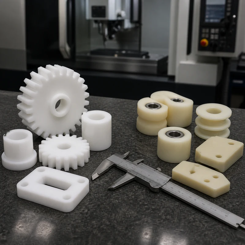
Acetal vs Nylon: CNC Machining and Material Selection Guide

Acetal and nylon are two of the most useful engineering plastics for machined gears, rollers, bushings, guides, and structural components. They can look similar on a drawing, but they respond differently to humidity, impact, sustained load, friction, and tight tolerances. Acetal is usually the more predictable choice for dimensional stability and smooth precision motion. Nylon is often stronger when a component must absorb shock, tolerate abrasion, or flex without cracking.

This is not a simple good-versus-bad comparison. Both material families contain multiple grades, fillers, and stock forms. The right decision comes from the actual load case, environment, geometry, tolerance scheme, and inspection condition. This guide compares acetal (often specified as POM or by the Delrin trade name) with common machinable nylons from a design-for-manufacturing perspective.

Acetal vs Nylon: Quick Engineering Comparison

Decision factor Acetal / POM Nylon
Typical design priority Stable dimensions and low-friction precision motion Toughness, impact absorption, and abrasion resistance
Moisture response Low absorption; comparatively stable in humidity Absorbs moisture; dimensions and properties can change
Stiffness Generally high and consistent Grade- and moisture-dependent; often more compliant
Impact behavior Good, but less forgiving at notches Generally tougher under shock and repeated loading
Wear and sliding Excellent for controlled sliding and gears Excellent for wear pads, guides, and rugged contact
Machining behavior Clean chips and good tolerance control Can produce stringy chips and move after unclamping
Creep under load Must be checked Must be checked; reinforced grades may help
Best starting point Close fits, valve parts, precision gears, spacers Wear pads, pulleys, rollers, impact-loaded components

These are broad tendencies rather than certified values. Resin type, conditioning, reinforcement, stock-production method, temperature, test direction, and supplier all matter. Always approve the exact grade using its current technical data and any required compliance documentation.

What Is Acetal?

Acetal is the engineering-plastic family known chemically as polyoxymethylene, or POM. It is available as homopolymer and copolymer formulations. Delrin is a trade name associated with a particular acetal homopolymer, so a drawing that says only “Delrin” may not be equivalent to every generic acetal grade. Procurement documents should identify the exact resin or an approved-equivalent rule.

Machined acetal is valued for stiffness, low friction, fatigue performance, clean machinability, and low moisture absorption. These traits make it a practical choice for dimensional spacers, small gears, bearing cages, valve components, electrical insulators, and mechanisms that need repeatable motion. It also tends to produce a crisp machined surface when tools are sharp and heat is controlled.

Homopolymer vs Copolymer POM

Homopolymer POM often offers somewhat higher stiffness and strength, while copolymer grades may provide improved resistance to hot water, alkaline environments, and centerline porosity in larger cross-sections. The meaningful difference depends on grade and stock size. For a sealing bore, pressure component, or thick machined section, do not substitute between them without engineering review.

What Is Nylon?

Nylon refers to a broad polyamide family rather than one uniform material. Nylon 6, nylon 6/6, cast nylon, nylon 12, and reinforced or lubricant-filled grades can behave quite differently. Common nylons combine toughness, fatigue resistance, and excellent abrasion performance, making them useful for rollers, sprockets, wear strips, pulleys, guides, and mechanical components exposed to vibration or intermittent shock.

The defining design issue is moisture absorption. Nylon equilibrates with its surroundings, and absorbed water can change its size, stiffness, and toughness. That can be beneficial for impact behavior but problematic for a close sliding fit or a tightly located hole pattern. Engineering and inspection must agree on whether dimensions apply to dry-as-machined, conditioned, or service-equilibrated material.

The Differences That Matter in Real Parts

Dimensional Stability and Moisture

Acetal is normally easier to control when humidity changes or when the part has a close fit. Nylon can swell after machining as it absorbs moisture, and the amount is affected by grade, wall thickness, time, and exposure. A tolerance that is achievable at the machine may not represent the dimension after conditioning or field service.

For nylon, identify the conditioning state on the drawing or purchase specification. Allow clearance where function permits, avoid blanket tight tolerances, and inspect at a controlled temperature and moisture condition. For either plastic, thin walls and asymmetric stock removal can release internal stress and cause movement.

Stiffness, Toughness, and Impact

Acetal is often selected when rigidity preserves gear alignment, bearing clearance, or positional accuracy. Nylon is usually more forgiving under impact and repeated deflection. Yet geometry can outweigh the generic material trend: a sharp corner, thin snap arm, press fit, or molded-in stress raiser can fail even in a nominally tough resin.

Use generous transitions, remove sharp internal corners, distribute fastener loads, and verify short-term strength separately from long-term creep. Filled grades can increase stiffness but may reduce impact strength or create direction-dependent behavior.

Friction, Wear, and Counterface

Both families can work well in sliding mechanisms. Acetal commonly provides smooth low-friction motion and predictable gear or bearing geometry. Nylon is widely used where abrasive contact and shock occur together. Actual life depends on pressure, velocity, heat generation, lubrication, debris, shaft material, surface finish, alignment, and duty cycle—not the plastic name alone.

A wear pair should be tested as a system. A very rough metal shaft can rapidly abrade a polymer, while an excessively smooth or incompatible counterface may not retain lubricant. Filled or internally lubricated grades should be evaluated when dry running or high duty is expected.

Temperature, Creep, and Chemical Exposure

Neither material behaves like a metal under sustained heat and clamp load. Strength and modulus fall as temperature rises, and creep can relax a bolted joint or distort a bearing seat over time. Nylon grades may retain useful toughness at elevated temperature, while acetal may keep dimensions more predictably in ordinary humid service. Grade-specific curves are essential near any limit.

Both resist many oils, greases, and fuels, but neither is chemically universal. Check the exact fluid, concentration, temperature, stress level, and exposure duration. Cleaning agents, thread lockers, and assembly lubricants deserve the same review as the primary process chemical.

CNC Machining Acetal and Nylon

Machining issue Acetal planning Nylon planning
Cutting edge Sharp polished carbide; maintain a real chip Sharp positive geometry; prevent rubbing and stringy recutting
Heat control Evacuate chips and avoid dwell Control heat carefully because local softening encourages movement
Workholding Broad support without crushing Support flexible walls and avoid clamp distortion
Finishing pass Allow the part to stabilize before final sizing Rough, relax, then finish when tight geometry warrants it
Threads Good detail, but avoid excessive interference Use adequate engagement; inserts or through-bolts may be safer
Inspection Control temperature and fixturing Define moisture condition as well as temperature

Successful CNC plastic machining removes heat with the chip. Rubbing, dull tools, excessive spindle speed, or repeated chip recutting can smear an edge and build residual stress. Air or a verified compatible coolant can help, but the fluid must not attack the polymer or contaminate a regulated part.

Practical Acetal Machining Guidance

  • Use stable, traceable stock and confirm homopolymer or copolymer before production.
  • Keep cutting tools sharp and avoid dwell marks at finished surfaces.
  • Support thin rings and long walls without creating ovality or clamp witness.
  • Use realistic press-fit allowances; excessive interference can split a hub over time.
  • Deburr by controlled cutting rather than melting or heavy edge rounding.

Practical Nylon Machining Guidance

  • State the material grade and conditioning state explicitly.
  • Use positive cutting geometry and evacuate continuous chips safely.
  • For tight features, consider rough machining followed by stress relaxation and finish machining.
  • Allow the part to stabilize before final measurement.
  • Protect long, flexible features from tool pressure and workholding distortion.

How to Choose by Application

Application condition Likely starting point What to verify
Precision gear or index component Acetal Tooth load, backlash, temperature, lubricant, and life
Close-fit bushing in changing humidity Acetal PV limit, shaft finish, clearance, and creep
Impact-loaded roller or pulley Nylon Shock load, moisture state, bearing retention, and wear
Wear pad or guide rail Nylon Counterface, debris, pressure, velocity, and lubrication
Valve or fluid-handling component Acetal grade selected for media Chemical compatibility, pressure, temperature, and porosity
Large structural plastic plate Cast nylon may be attractive Flatness, internal stress, conditioning, and creep
Food or medical contact part Certified grade only Applicable regulation, traceability, cleaning, and validation

Design Rules That Reduce Failure Risk

  1. Specify the family and exact grade. “Plastic,” “nylon,” or “acetal” alone leaves too much room for substitution.
  2. Define the service environment. Include humidity, immersion, temperature range, chemicals, UV exposure, and duty cycle.
  3. Tolerance only the interfaces that matter. Plastic dimensions respond to temperature, moisture, stress, and fixturing.
  4. Avoid sharp stress concentrators. Add corner radii and smooth section changes.
  5. Design fasteners for creep. Use washers, shoulders, metal inserts, or through-bolts where appropriate.
  6. Account for thermal expansion. Do not trap a long plastic component between rigid metal boundaries without clearance.
  7. Separate cosmetic and functional surfaces. Deburring, polishing, and protective handling can affect critical edges.

Cost: Compare the Finished System, Not Stock Price

Standard nylon stock may appear less expensive than a specified acetal grade, but material price is only one input. Add machining time, stabilization steps, scrap risk, inspection, assembly method, lubrication, maintenance, and expected service life. A stable acetal part may be cheaper if it avoids post-machining movement; a tougher nylon component may be cheaper if it survives shock and abrasive duty longer.

RFQ Checklist

  • Controlled 3D model and 2D drawing
  • Exact resin, grade, color, filler, and approved equivalents
  • Stock form and required material certification
  • Quantity and prototype-to-production plan
  • Critical datums, fits, tolerances, and inspection condition
  • Load, speed, temperature, humidity, chemicals, and expected life
  • Counterface material, finish, lubrication, and debris exposure
  • Threads, inserts, press fits, assembly torque, and cosmetic requirements

MTSPi can review these inputs through its CNC machining services, dedicated acetal machining and nylon machining capabilities, and quality assurance workflow.

Frequently Asked Questions

Is Delrin the same as acetal?

Delrin is a trade name for a specific POM homopolymer. Acetal is the wider POM family, which also includes copolymers. Use the exact grade on production documents.

Which material holds a tighter tolerance?

Acetal is usually the easier starting point because it absorbs less moisture. Geometry, stock stress, temperature, fixturing, and measurement method still control the achievable result.

Which is better for gears?

Acetal suits precise, low-friction gears; nylon can suit tougher or shock-loaded gears. Tooth load, heat, lubrication, backlash, and life testing should decide.

Can nylon be machined accurately?

Yes. Accurate nylon parts require suitable stock, sharp tools, controlled heat and workholding, stabilization, and a defined moisture condition.

Can both materials use threaded inserts?

Yes, but insert style, installation method, wall thickness, torque, temperature, and creep must be validated for the exact grade.

Conclusion

Choose acetal when stable dimensions, stiffness, clean machinability, and smooth low-friction motion lead the requirements. Choose nylon when toughness, abrasion resistance, and impact absorption matter more. Then verify the decision against the exact grade, conditioning state, environment, tolerance plan, counterface, and lifetime load—not a generic property chart.

Related MTSPi Resources

Request A Quote

We'll Send You Back with Price Immediately!

DEC 1-31

XMAS SPECEIL

Up to

40% off

Acetal vs Nylon: CNC Machining and Material Selection Guide

We'll Send You Back with Price Immediately!