

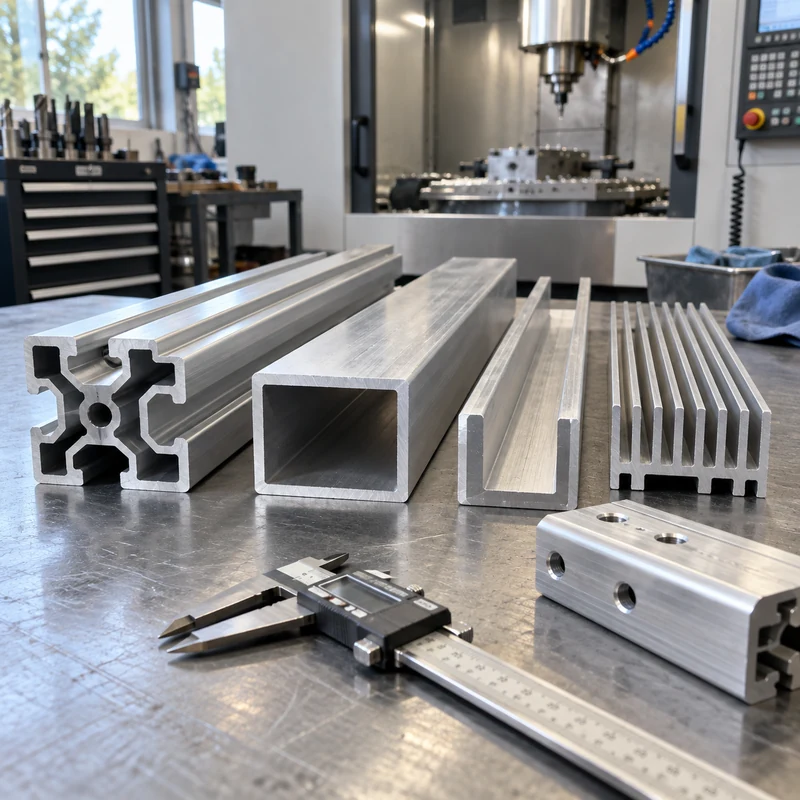
An aluminum extrusion profile is a continuous section used to build rails, frames, enclosures, heat sinks, and many other components. Selecting one requires more than matching an outline in a catalog. The section must carry the load, accept the intended fasteners, remain practical to manufacture, and leave enough material for any precision machining.
Quick answer: Start with the assembly interfaces and load direction, then choose the section, alloy and temper, extrusion tolerances, and finishing sequence. Extrusion creates the repeated cross section; CNC machining adds local holes, pockets, accurate end faces, and other features that change along the length.
Profile Shapes and Their Practical Tradeoffs
| Section | Useful function | What to check before ordering |
|---|---|---|
| T-slot framing | Adjustable brackets, guarding, and equipment frames | Actual slot dimensions, nut engagement, compatible hardware, joint rigidity |
| Angle or open channel | Edges, guides, supports, and simple brackets | Loading direction, twisting, mounting access, exposed edges |
| Hollow tube | Lightweight frames and protected internal space | Wall thickness, internal access, joining method, drainage |
| Finned section | Thermal-management components | Fin spacing, airflow, base flatness, attachment to the heat source |
| Custom enclosure | Integrated rails, cover interfaces, and mounting features | Tooling cost, cover fit, machining stock, finish buildup |
Extruders also classify sections as solid, hollow, or semi-hollow. Those classifications concern die geometry, including enclosed or partially enclosed spaces. A narrow opening can make an apparently simple shape difficult to produce. Ask the extruder to confirm the classification and feasibility rather than assigning it solely from appearance.
Use Stiffness and Joint Behavior to Select the Section
Two rails with similar outside dimensions can perform differently because the metal is distributed differently. For a simple beam under the same load and support conditions, bending deflection depends on elastic modulus and the section’s second moment of area. Turning a rectangular section through 90 degrees can therefore change deflection substantially.
For a machine frame, inspect the joints as carefully as the beams. A stiff rail attached through a slipping bracket may still allow poor positioning. Obtain the supplier’s section properties, model the real support conditions, and include the connection details. Do not select a larger rail merely because it looks more substantial.
Specify Alloy and Temper Together
6063 is commonly considered for complex profiles and appearance-sensitive applications; 6061 is often considered when strength and subsequent machining matter. Neither alloy name alone defines the finished performance. Temper, section thickness, manufacturing route, and any later thermal operations also matter.
Request the specified alloy and temper on the purchase order and material documentation. Where a design depends on a minimum mechanical property, use the applicable product specification rather than a generic internet value. Compare the requirements with your broader engineering material options before finalizing the drawing.
Keep Extrusion Tolerances Separate From Machined Tolerances
Profile dimensions, straightness, twist, cut length, and end squareness are separate requirements. A cross section that passes a dimensional check at one end can still cause assembly trouble over a long length. Establish the final assembly datums and identify which characteristics are controlled by extrusion and which require machining.
For example, an enclosure may accept ordinary extrusion variation on its outer walls while requiring an accurately machined connector opening. Dimension that opening from functional mounting datums, not from a decorative surface that varies between extrusion lots. This distinction makes the drawing easier to quote and inspect.
Design the Section for Secondary CNC Work
Relatively balanced walls and smooth transitions help the extrusion process. For downstream machining, also reserve accessible clamping areas and sufficient stock on precision faces. A thin lip may deform under a vise even though it was easy to extrude. Consider a supporting fixture or revised clamping location before increasing cutting pressure.
- Place local features where drills and milling cutters can reach them.
- Check that a tapped hole has enough engagement after finishing.
- Allow an inspection probe or gauge to reach critical features.
- Identify surfaces that must remain free of clamp marks.
- Discuss the machining sequence when substantial material removal could release distortion.
The comparison of extrusion and CNC machining is useful when deciding whether to start from a profile or machine the entire part from stock.
Check Hardware Fit After Surface Treatment
A nominal frame series is not a complete hardware specification. Confirm the groove opening, internal seat, nut dimensions, screw length, and access for assembly. Parts from different systems can look compatible without sharing those details.
Specify whether fit requirements apply before or after coating. Anodizing or another finish can change functional clearances, and masked areas may be needed. Agree on visible-surface acceptance and sample approval with the surface finishing requirements, especially where adjacent components must match.
Compare Total Cost With a Simple Break-Even Model
Compare complete delivered components, including the die, material, cutting, machining, finishing, inspection, and scrap. A custom section can save downstream work, but those savings must repay the tooling and qualification effort.
Illustrative calculation, not a quotation: if custom tooling costs $2,400 and the resulting section saves $6 per finished component, the tooling-only break-even quantity is 400 components. Add qualification costs and any minimum-order inventory before making the purchase decision. Obtain both routes against the same drawing revision.
What to Include in an RFQ
Provide the cross-section drawing, finished length, quantity, alloy and temper, critical tolerances, finish, assembly interfaces, and expected annual demand. Separate raw-profile requirements from the finished-part drawing. Include a model for local machined features and clarify ownership of any custom die.
Frequently Asked Questions
Can extrusion create holes at specific positions along a rail?
Discrete cross holes and local pockets generally require secondary operations. Extrusion produces the continuous section; their locations must be defined on the finished-part drawing.
Is a custom profile always cheaper than a standard section?
No. It depends on tooling, order quantity, purchased material, and the operations it removes. A standard section can remain preferable for uncertain demand or frequent revisions.
Should every surface have a tight tolerance?
No. Apply tight controls to functional interfaces and justify them through the assembly. Unnecessary precision increases cost without necessarily improving performance.