

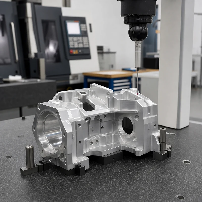
A datum is an exact theoretical point, axis, or plane used to establish a measurement reference. A physical surface, hole, slot, or other feature on the part is a datum feature; inspection equipment or fixture contacts simulate that feature to establish the datum. Keeping those terms distinct helps a drawing translate into repeatable machining, assembly, and inspection.
For precision parts, MTSPi connects drawing intent to setup planning, multi-operation transfer, and quality assurance so the same functional references guide production and measurement.
Datum, Datum Feature, and Datum Feature Simulator
| Term | Meaning | Example |
|---|---|---|
| Datum | Perfect theoretical reference | A plane derived from a mounting face |
| Datum feature | Real part feature identified on the drawing | The actual mounting face or locating bore |
| Datum feature simulator | Equipment that contacts or represents the feature | Surface plate, fixture pad, pin, mandrel, or CMM alignment |
The real feature contains manufacturing variation. The datum is ideal. The simulator creates a repeatable relationship between the real part and the ideal reference used for evaluation.
How a Datum Reference Frame Constrains a Part
A common primary-secondary-tertiary scheme follows the 3-2-1 principle. The primary datum feature typically contacts three points and removes three degrees of freedom. The secondary feature contacts two points and removes two more. The tertiary feature uses one point to remove the final degree of freedom. Together they establish the datum reference frame named in a feature-control frame.
| Datum order | Typical role | Degrees of freedom constrained |
|---|---|---|
| Primary (A) | Stable functional base or broad surface | Three |
| Secondary (B) | Side surface, bore, or slot establishing direction | Two |
| Tertiary (C) | Final stop or clocking feature | One |
Why Datum Order Matters
A-B-C is not interchangeable with B-A-C. The first reference dominates how the part is oriented, while later references finish its location. Changing the order can change the measured position or orientation of features. Datum precedence should therefore reflect assembly function, not simply whichever surface is easiest for the machinist to touch.
Datums Across Design, Machining, and Inspection
| Stage | How datums are used | Failure if inconsistent |
|---|---|---|
| Design | Express functional relationships through GD&T | A drawing may control the wrong interface |
| Process planning | Choose workholding and operation sequence | Tolerance stack grows across re-clamping |
| Machining | Set work coordinates and transfer references | Features shift between setups |
| Inspection | Align CMM or gaging to the specified frame | Good parts fail or bad parts pass |
| Assembly | Locate mating components | Fit, sealing, motion, or alignment problems |
Choosing Functional Datum Features
- Start with the surfaces or axes that locate the part in its real assembly.
- Choose a primary feature that is stable, accessible, and large enough to establish orientation.
- Use secondary and tertiary features that control functional direction and clocking.
- Avoid rough cast, flexible, interrupted, or easily damaged features unless they truly represent function.
- Consider how the features can be simulated in both production fixtures and inspection equipment.
- Keep the datum scheme compatible with service loads, mating parts, and maintenance needs.
Common Datum Feature Types
Planar surfaces
Mounting faces are common primary datum features because they can provide stable orientation. Flatness and contact distribution still matter.
Holes and cylindrical features
A bore can establish a datum axis, while a pin pattern can locate and clock a part. Clearance, material boundary modifiers, and simulator type affect how the frame is established.
Slots and tabs
Center planes derived from width features can locate a part while allowing controlled movement in another direction.
Datum targets
Targets define selected points, lines, or areas and are useful for castings, forgings, sheet structures, and irregular surfaces where full-surface contact would be unstable.
Datums Versus Machine Zero
The machine coordinate system and work offset are programming tools. A drawing datum is a design and inspection reference. A programmer may align a work offset with a datum for convenience, but they are not automatically the same. Setup documentation should explain the transformation so dimensions remain traceable through every operation.
Multi-Setup and 5-Axis Parts
Complex parts often cannot retain the functional datums in one clamping. Process planners may create temporary machining references, precision soft jaws, or qualified fixture features. The important point is to control the transfer back to the drawing reference frame. On 5-axis CNC machining projects, a strong datum plan can reduce re-clamping, but inspection still has to reconstruct the specified frame correctly.
Frequent Datum Mistakes
- Labeling a theoretical plane as though it were the physical surface.
- Selecting cosmetic or convenient faces instead of functional interfaces.
- Using unstable features that rock or deform in a fixture.
- Failing to preserve datum relationships across secondary operations.
- Inspecting from shop-friendly references that differ from the drawing.
- Over-constraining a part with incompatible fixture contacts.
- Omitting datum order or material-boundary requirements where they matter.
Drawing Review Checklist
- Do A, B, and C reflect how the part mates and carries load?
- Can each datum feature be reached by the fixture and CMM probe?
- Are flexible or unfinished surfaces controlled appropriately?
- Does each positional or orientation tolerance reference the intended frame?
- Are datum targets, basic dimensions, and feature-control frames unambiguous?
- Can the machining sequence preserve or accurately re-establish the frame?
FAQ
Can a hole be a datum?
Yes. The hole is the datum feature, and its derived axis can establish the datum.
What do Datum A, B, and C mean?
They identify datum features in precedence order: primary, secondary, then tertiary.
Does every CNC part need three datums?
No. The reference structure should be only as complex as the functional geometry requires.
Can an inspection setup use different datums?
Intermediate checks may use process references, but final acceptance must evaluate requirements from the datum reference frame specified on the drawing.