Categories
Blog CNC Materials Quality & Tolerances

Datums in CNC Machining: A Practical GD&T and Inspection Guide

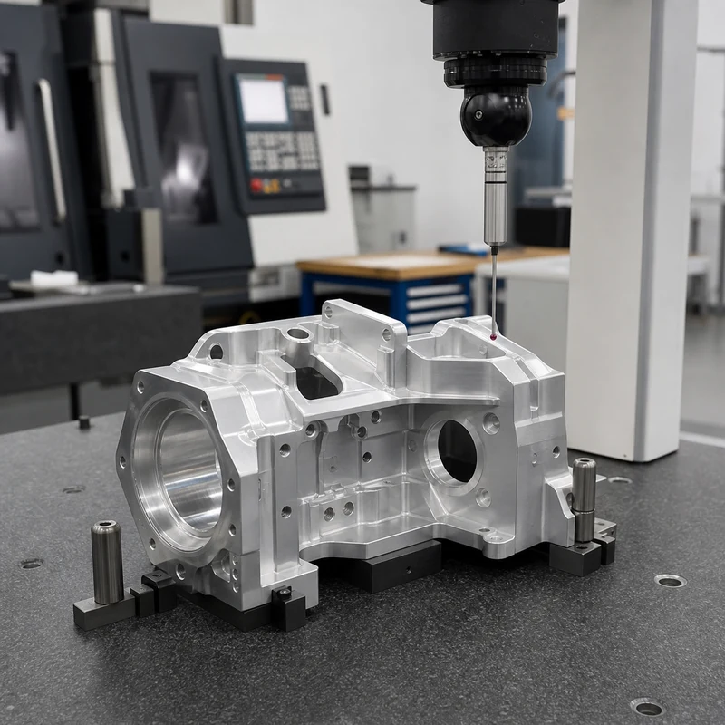
A datum is an exact theoretical point, axis, or plane used to establish a measurement reference. A physical surface, hole, slot, or other feature on the part is a datum feature; inspection equipment or fixture contacts simulate that feature to establish the datum. Keeping those terms distinct helps a drawing translate into repeatable machining, assembly, and inspection.

For precision parts, MTSPi connects drawing intent to setup planning, multi-operation transfer, and quality assurance so the same functional references guide production and measurement.

Datum, Datum Feature, and Datum Feature Simulator

Term Meaning Example
Datum Perfect theoretical reference A plane derived from a mounting face
Datum feature Real part feature identified on the drawing The actual mounting face or locating bore
Datum feature simulator Equipment that contacts or represents the feature Surface plate, fixture pad, pin, mandrel, or CMM alignment

The real feature contains manufacturing variation. The datum is ideal. The simulator creates a repeatable relationship between the real part and the ideal reference used for evaluation.

How a Datum Reference Frame Constrains a Part

A common primary-secondary-tertiary scheme follows the 3-2-1 principle. The primary datum feature typically contacts three points and removes three degrees of freedom. The secondary feature contacts two points and removes two more. The tertiary feature uses one point to remove the final degree of freedom. Together they establish the datum reference frame named in a feature-control frame.

Datum order Typical role Degrees of freedom constrained
Primary (A) Stable functional base or broad surface Three
Secondary (B) Side surface, bore, or slot establishing direction Two
Tertiary (C) Final stop or clocking feature One

Why Datum Order Matters

A-B-C is not interchangeable with B-A-C. The first reference dominates how the part is oriented, while later references finish its location. Changing the order can change the measured position or orientation of features. Datum precedence should therefore reflect assembly function, not simply whichever surface is easiest for the machinist to touch.

Datums Across Design, Machining, and Inspection

Stage How datums are used Failure if inconsistent
Design Express functional relationships through GD&T A drawing may control the wrong interface
Process planning Choose workholding and operation sequence Tolerance stack grows across re-clamping
Machining Set work coordinates and transfer references Features shift between setups
Inspection Align CMM or gaging to the specified frame Good parts fail or bad parts pass
Assembly Locate mating components Fit, sealing, motion, or alignment problems

Choosing Functional Datum Features

  • Start with the surfaces or axes that locate the part in its real assembly.
  • Choose a primary feature that is stable, accessible, and large enough to establish orientation.
  • Use secondary and tertiary features that control functional direction and clocking.
  • Avoid rough cast, flexible, interrupted, or easily damaged features unless they truly represent function.
  • Consider how the features can be simulated in both production fixtures and inspection equipment.
  • Keep the datum scheme compatible with service loads, mating parts, and maintenance needs.

Common Datum Feature Types

Planar surfaces

Mounting faces are common primary datum features because they can provide stable orientation. Flatness and contact distribution still matter.

Holes and cylindrical features

A bore can establish a datum axis, while a pin pattern can locate and clock a part. Clearance, material boundary modifiers, and simulator type affect how the frame is established.

Slots and tabs

Center planes derived from width features can locate a part while allowing controlled movement in another direction.

Datum targets

Targets define selected points, lines, or areas and are useful for castings, forgings, sheet structures, and irregular surfaces where full-surface contact would be unstable.

Datums Versus Machine Zero

The machine coordinate system and work offset are programming tools. A drawing datum is a design and inspection reference. A programmer may align a work offset with a datum for convenience, but they are not automatically the same. Setup documentation should explain the transformation so dimensions remain traceable through every operation.

Multi-Setup and 5-Axis Parts

Complex parts often cannot retain the functional datums in one clamping. Process planners may create temporary machining references, precision soft jaws, or qualified fixture features. The important point is to control the transfer back to the drawing reference frame. On 5-axis CNC machining projects, a strong datum plan can reduce re-clamping, but inspection still has to reconstruct the specified frame correctly.

Frequent Datum Mistakes

  • Labeling a theoretical plane as though it were the physical surface.
  • Selecting cosmetic or convenient faces instead of functional interfaces.
  • Using unstable features that rock or deform in a fixture.
  • Failing to preserve datum relationships across secondary operations.
  • Inspecting from shop-friendly references that differ from the drawing.
  • Over-constraining a part with incompatible fixture contacts.
  • Omitting datum order or material-boundary requirements where they matter.

Drawing Review Checklist

  • Do A, B, and C reflect how the part mates and carries load?
  • Can each datum feature be reached by the fixture and CMM probe?
  • Are flexible or unfinished surfaces controlled appropriately?
  • Does each positional or orientation tolerance reference the intended frame?
  • Are datum targets, basic dimensions, and feature-control frames unambiguous?
  • Can the machining sequence preserve or accurately re-establish the frame?

FAQ

Can a hole be a datum?

Yes. The hole is the datum feature, and its derived axis can establish the datum.

What do Datum A, B, and C mean?

They identify datum features in precedence order: primary, secondary, then tertiary.

Does every CNC part need three datums?

No. The reference structure should be only as complex as the functional geometry requires.

Can an inspection setup use different datums?

Intermediate checks may use process references, but final acceptance must evaluate requirements from the datum reference frame specified on the drawing.
Related MTSPi Resources

Categories
Blog CNC Materials Industries & Applications Quality & Tolerances

CNC Machining for Medical Devices: Materials, Applications, and Quality Checks

Quick answer: CNC machining is used for medical device prototypes, surgical tools, instrument parts, housings, fixtures, test components, and precision hardware. Medical parts often require careful material selection, clean machining, dimensional inspection, traceability, and clear documentation.

CNC Machining for Medical Devices

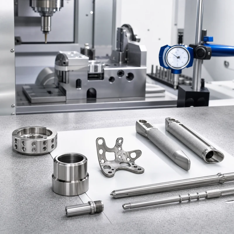
Medical machining is not only about tight tolerances. Buyers must consider biocompatible or application-appropriate materials, clean edges, surface finish, inspection records, and consistent communication about critical features.

Key Points for Buyers and Engineers

Topic What to know Practical impact
Materials Stainless steel, titanium, aluminum, PEEK, PC, PPSU Material must match use and regulatory expectations.
Features Small holes, slots, threads, mating surfaces Tool access and burr control are important.
Inspection CMM, gauges, visual checks, reports Confirms critical dimensions and drawing requirements.
Finish Polishing, passivation-like cleaning, anodizing, marking Affects appearance, corrosion behavior, and cleanliness.

How This Affects CNC Machined Parts

Medical prototypes may use both milling and turning. The process should be selected by geometry, material, tolerance, surface finish, and inspection requirements rather than by price alone.

Design and Purchasing Checklist

  • Mark critical dimensions and datums clearly.
  • Confirm material grade and certificate needs.
  • Define burr, edge break, and cleanliness expectations.
  • Request inspection reports when fit is critical.
  • Review finish compatibility before production.

Related MTSPi Resources

FAQ

What medical parts can be CNC machined?

Instrument components, housings, fixtures, prototype parts, surgical tool components, and precision hardware can be machined.

Is titanium used for medical CNC parts?

Yes, titanium is used in certain medical applications because of strength, corrosion resistance, and biocompatibility considerations.

Do medical CNC parts need CMM inspection?

Many precision medical parts benefit from CMM inspection, especially when GD&T or assembly-critical features are present.

Need help with medical CNC machining?

Send drawings, material, quantity, finish, tolerance notes, and application requirements. MTSPi can review manufacturability before quoting.

Contact MTSPi for engineering and quote support

Practical Buyer Notes

Medical machining pages need depth because the topic involves more than precision. Cleanliness, burr control, traceability, material documentation, surface finish, and inspection expectations can all be important.

The page should avoid making regulatory claims that are too broad. Instead, it should explain practical manufacturing controls for prototypes, test fixtures, instruments, housings, and precision medical hardware.

How to Evaluate This Topic on a Real Drawing

Decision point Recommended approach Why it matters
Material Confirm stainless steel, titanium, PEEK, PC, or other grade Material must match function and documentation needs
Burr control Define edge breaks and clean transitions Sharp edges can create safety and assembly issues
Inspection Use CMM, gauges, and reports for critical features Supports part verification
Cleanliness Plan cleaning and packaging expectations Protects parts during handling and shipment

Common Mistakes to Avoid

  • Using vague material names instead of exact grades.
  • Ignoring burrs on small holes, slots, and edges.
  • Treating surface finish as cosmetic only.
  • Failing to define inspection records before production.

Recommended MTSPi Review Workflow

MTSPi should review medical-related CNC parts with extra attention to material, edge condition, finish, and critical dimensions. The page should explain this clearly without overstating certification scope.

  1. Confirm the part function, operating environment, and assembly risk.
  2. Review material, process, tolerance, surface finish, and inspection requirements together.
  3. Separate critical features from general dimensions so cost is not wasted on non-functional details.
  4. Use related resources such as CNC materials, surface treatment, and quality assurance to complete the specification.
  5. Send the final drawing package to MTSPi for quote review before production.

What to Send for a Faster Quote

Send CAD, drawing, material grade, finish, required reports, cleaning expectations, critical dimensions, and whether the part is for prototype, fixture, or production use.

  • 3D CAD file and 2D drawing with revision number.
  • Material grade or acceptable alternatives.
  • Quantity, delivery target, and whether samples are required first.
  • Critical dimensions, thread callouts, finish notes, and inspection requirements.
  • Application notes when the part is used in heat, moisture, wear, vibration, or visible assemblies.

Deeper Engineering Notes

For medical CNC machining, the strongest page is not just a definition. It should help a buyer decide what information belongs on the drawing, what questions to ask a supplier, and which details affect cost, quality, and delivery. In real RFQ work, the important details are usually material traceability, burr control, clean handling, inspection reports, and revision discipline. These details decide whether the supplier can quote confidently or has to return with repeated questions.

The common risk is making broad claims without defining the exact medical application and documentation needs. That risk can make the content look complete on the surface but weak in a real manufacturing situation. A stronger specification connects the topic to material behavior, machine access, tolerance control, finishing, and inspection before the order is released.

Example Specification Review

Review area Question to answer Good specification practice
Function What does this feature or part need to do? Describe the load, fit, motion, appearance, sealing, or assembly requirement.
Material Is the selected material suitable for the environment? Confirm strength, heat, corrosion, wear, chemical exposure, and cosmetic needs.
Geometry Can the feature be reached by standard tools? Review depth, corner radius, wall thickness, tool clearance, and setup direction.
Tolerance Which dimensions are truly critical? Use tight tolerances only where function requires them and keep general dimensions practical.
Verification How will acceptance be checked? Define gauges, CMM checks, roughness measurement, thread inspection, or visual standards when needed.

How This Page Should Support Ranking

This topic can attract both beginner searches and buyer searches. The beginner wants a clear answer; the buyer wants enough detail to make a manufacturing decision. A page has a better chance to rank when it answers the simple question first, then adds examples, process limits, design notes, comparison tables, and practical next steps.

That is also why internal links should be helpful rather than forced. A reader should naturally move from this page to a process page, material page, surface finish page, inspection page, or quote page only when that next step solves a real question.

Conclusion

CNC machining can support medical device development when material, cleanliness, tolerance, finish, and inspection expectations are defined clearly from the start.

Categories
Blog Quality & Tolerances

What Is CMM Inspection? Complete Guide to Coordinate Measuring Machines for CNC Parts

Quick answer: CMM inspection uses a coordinate measuring machine to measure part features in three-dimensional space. It checks dimensions, hole positions, profiles, flatness, perpendicularity, true position, datums, and GD&T requirements. For CNC machined parts, CMM inspection is most useful when features are tight, complex, datum-based, or critical to assembly.

What Is a CMM?

A CMM, or coordinate measuring machine, is an inspection system that measures points on a part using a probe or sensor. The machine records X, Y, and Z coordinates and compares them with the drawing or CAD model. This allows inspectors to verify whether a machined part is within tolerance.

CMM inspection is common for precision CNC parts because many features cannot be judged reliably with calipers alone. Hole patterns, datum relationships, true position, perpendicularity, flatness, and complex profiles need a measurement method that understands the part in 3D space.

What CMM Inspection Can Measure

Feature What CMM checks Why it matters
Hole position Location relative to datums or other holes Controls assembly alignment
Flatness Variation across a surface Important for sealing, mounting, and contact faces
Perpendicularity Angle relationship between axes or surfaces Important for housings, brackets, and fixtures
Profile Deviation from CAD surface or drawing profile Useful for complex milled geometry
True position GD&T-controlled feature location Common for precision hole patterns
Distance and size Lengths, widths, diameters, depths Confirms basic drawing dimensions

How CMM Inspection Works

First, the inspector reviews the drawing and identifies datums, critical features, tolerance zones, and measurement requirements. The part is cleaned and fixtured so it sits in a repeatable position. The CMM then touches or scans selected points. Software compares the measured data with the nominal CAD or drawing values and creates a report.

For repeat production, a CMM program can be saved and reused. This helps measure the same features consistently across batches. For first article inspection, the report may include a broader set of dimensions to validate the initial production process.

CMM Inspection vs Manual Inspection

Inspection method Best for Limitations
Calipers Quick checks of general dimensions Limited for complex geometry and high precision
Micrometers Accurate outside diameters and thickness Feature access and operator method matter
Pin / plug gauges Hole size and fit checks Does not fully describe position or geometry
Thread gauges Internal or external thread fit Does not measure all thread geometry
CMM Datum-based geometry, GD&T, complex parts More time and cost than simple manual checks

When Should Buyers Request CMM Inspection?

  • The part has tight tolerance hole patterns.
  • The drawing uses GD&T such as true position, profile, flatness, or perpendicularity.
  • The part must fit into a larger assembly with little adjustment.
  • The part has multiple machined sides or complex surfaces.
  • The order requires first article inspection or documented quality records.
  • The cost of failure is higher than the cost of measurement.

What Should a CMM Report Include?

A useful CMM report should include part name, drawing number, revision, inspection date, measured features, nominal values, tolerance limits, actual measurements, deviation, pass/fail result, datum reference, and inspector notes. For regulated or high-value projects, material certificate, finish confirmation, and first article documentation may also be needed.

GD&T, Datums, and CMM Inspection

GD&T gives more precise control over how features relate to each other. A hole may pass a simple diameter check but still fail true position if it is not located correctly from the datums. CMM inspection is strong in this situation because it can evaluate the feature within a coordinate system based on the drawing’s datum structure.

If the datum structure is unclear, inspection becomes uncertain. Buyers should make sure the drawing identifies primary, secondary, and tertiary datums where needed. For CNC suppliers, clear datums also help plan workholding and machining sequence.

CMM Inspection for CNC Milling and Turning

For CNC milled parts, CMM inspection is useful for hole patterns, pockets, flatness, profiles, and multi-side relationships. For CNC turned parts, it can support checks for bores, faces, grooves, concentric relationships, cross holes, and secondary milled features. It works best when the drawing clearly separates critical and non-critical dimensions.

How to Reduce Inspection Cost Without Increasing Risk

  • Identify critical dimensions instead of requiring a full report for every feature.
  • Use general tolerance notes for non-critical dimensions.
  • Provide CAD and drawing files together.
  • Define datum structure clearly.
  • Use gauges for simple features and CMM for features that need 3D relationships.
  • Agree on sampling quantity before production.

FAQ

Is CMM inspection required for every CNC part?

No. Many simple parts can be checked with calipers, micrometers, gauges, or visual inspection. CMM is most valuable for precision, complex, or GD&T-controlled parts.

Can CMM inspect threads?

CMM can check thread location and related geometry, but thread fit is usually checked with go/no-go thread gauges.

What is the difference between CMM and FAI?

CMM is a measurement method. First article inspection is a broader process that may include CMM measurements, material checks, finish checks, and documentation.

Does CMM inspection add lead time?

Yes, it can add inspection time, especially for complex reports. But it can reduce risk when parts are expensive or assembly-critical.

What files help CMM inspection?

A 2D drawing with tolerances and datums is essential. A 3D CAD model can help with programming and profile comparison.

Need inspection support for precision parts?

Send your drawing, GD&T notes, CAD file, and critical dimensions. MTSPi can review the right inspection method before quoting.

Contact MTSPi for CNC inspection support

Conclusion

CMM inspection helps confirm that CNC machined parts match the drawing in three-dimensional space. It is most useful for complex geometry, datum-based tolerances, first article inspection, and parts where assembly risk is high.

Categories
Blog Quality & Tolerances

CMM Inspection Explained: How Coordinate Measuring Machines Check Parts

CMM inspection uses a coordinate measuring machine to capture accurate points on a part and compare them with a drawing or CAD model. It is one of the most important measurement methods for precision machined components, especially when parts include GD&T callouts, true position, flatness, profile, or complex relationships between features.

For high-value parts, CMM results can support first article inspection, production approval, and ongoing quality control. MTSPi includes CMM and other inspection methods as part of its quality assurance workflow when the drawing requires documented measurement.

How CMM Inspection Works

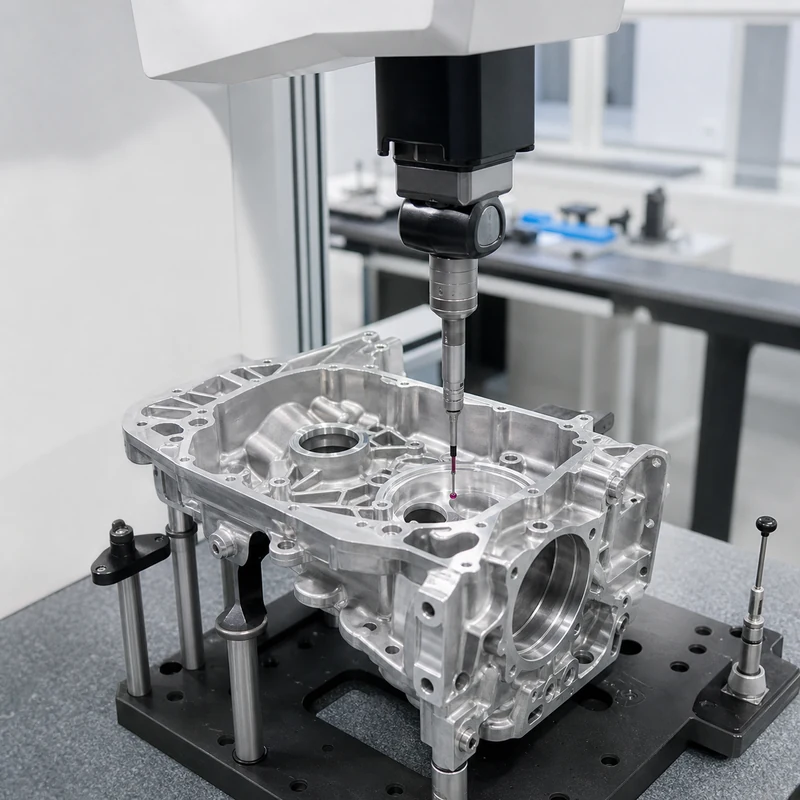
A CMM records coordinates in X, Y, and Z. A probe touches or scans the workpiece, and software uses the measured points to calculate dimensions, feature locations, and geometric tolerances. The part is usually held on a granite table with fixtures that keep it stable during inspection.

  • The operator imports the CAD model or enters drawing dimensions.
  • The part is aligned to a datum structure.
  • The probe measures selected features.
  • Software compares actual data with nominal values and tolerances.
  • A report shows pass/fail results and measured deviations.

Features Commonly Checked by CMM

Feature What CMM Can Confirm
Hole patterns True position, diameter, spacing, and depth references
Flat surfaces Flatness, parallelism, and datum relationships
Profiles and contours Surface profile against CAD geometry
Milled pockets Width, depth, corner location, and wall position
Turned parts Concentricity, runout, diameter, and length relationships

CMM vs Other Inspection Tools

Tool Best For Limitation
Caliper Quick general checks Limited accuracy and operator-dependent
Micrometer Accurate outside or inside dimensions Not ideal for complex feature relationships
CMM GD&T and multi-feature geometry Requires programming and setup time
Optical system Small features and non-contact checks May struggle with hidden surfaces

When to Request a CMM Report

Request CMM inspection when a part has tight tolerances, important assembly alignment, safety-critical function, or customer documentation requirements. If the part includes machining plus coating, it is useful to decide whether inspection should happen before finishing, after finishing, or both. This is especially important for close-fit holes, bearing seats, and sealing surfaces connected to surface treatment.

Related MTSPi Resources

FAQ

Is CMM inspection required for every part?

No. It is most useful for complex geometry, tight tolerance features, GD&T, and documented inspection requirements.

Can a CMM inspect plastic parts?

Yes, but fixturing and probe force should be chosen carefully because plastics may flex.

What is included in a CMM report?

Reports typically include measured dimensions, nominal values, tolerance limits, deviations, and pass/fail status.

Categories
Quality & Tolerances

CNC Machining Quality Inspection: CMM, Reports, Gauges and First Article Checks

CNC machining quality inspection is a key search topic for buyers who need reliable custom parts, accurate dimensions, practical material advice, and clear supplier communication. Before sending a drawing or placing an order, buyers should understand the process, cost drivers, tolerance requirements, material options, lead time, inspection needs, and the questions that separate a capable machine shop from a weak supplier.

Inspection Planning

Inspection should match part function. Critical dimensions, fit features, threads, surfaces, and datums need clear control.

Buyer Notes

For a smoother quote, prepare a 3D model, 2D drawing, target material, order quantity, surface finish, tolerance requirements, and any critical assembly information. Clear specifications reduce delays and help the supplier identify manufacturability risks early.

Common Measurement Tools

Calipers, micrometers, plug gauges, ring gauges, height gauges, surface roughness testers, and CMMs are commonly used.

Buyer Notes

For a smoother quote, prepare a 3D model, 2D drawing, target material, order quantity, surface finish, tolerance requirements, and any critical assembly information. Clear specifications reduce delays and help the supplier identify manufacturability risks early.

First Article Inspection

First article inspection checks early parts before full production continues. It helps catch problems before a batch is completed.

Buyer Notes

For a smoother quote, prepare a 3D model, 2D drawing, target material, order quantity, surface finish, tolerance requirements, and any critical assembly information. Clear specifications reduce delays and help the supplier identify manufacturability risks early.

Inspection Reports

Reports can include measured dimensions, tolerance results, material information, finish notes, and inspector approval.

Buyer Notes

For a smoother quote, prepare a 3D model, 2D drawing, target material, order quantity, surface finish, tolerance requirements, and any critical assembly information. Clear specifications reduce delays and help the supplier identify manufacturability risks early.

FAQ

How are CNC machined parts inspected?

For CNC machining quality inspection, the right answer depends on part geometry, material, tolerance, surface finish, quantity, and end-use requirements. A complete RFQ helps the supplier give a useful recommendation.

What is a CNC inspection report?

For CNC machining quality inspection, the right answer depends on part geometry, material, tolerance, surface finish, quantity, and end-use requirements. A complete RFQ helps the supplier give a useful recommendation.

What is first article inspection?

For CNC machining quality inspection, the right answer depends on part geometry, material, tolerance, surface finish, quantity, and end-use requirements. A complete RFQ helps the supplier give a useful recommendation.

When do I need CMM inspection?

For CNC machining quality inspection, the right answer depends on part geometry, material, tolerance, surface finish, quantity, and end-use requirements. A complete RFQ helps the supplier give a useful recommendation.

Practical Checklist Before Ordering

  • Confirm material grade, dimensions, tolerance, and surface finish.
  • Share both 3D files and 2D drawings when possible.
  • Identify critical features that affect fit, sealing, strength, or assembly.
  • Ask about sample lead time, MOQ, inspection reports, and packaging.
  • Compare quotes by specification, not only by unit price.

Conclusion

A good CNC machining decision balances design, material, tolerance, cost, lead time, and supplier capability. Buyers who prepare complete files and ask the right technical questions usually receive more accurate quotes, better parts, and fewer production surprises.

Categories
Quality & Tolerances

Precision CNC Machining: How Accuracy, Inspection and Quality Control Work

precision CNC machining is a key search topic for buyers who need reliable custom parts, accurate dimensions, practical material advice, and clear supplier communication. Before sending a drawing or placing an order, buyers should understand the process, cost drivers, tolerance requirements, material options, lead time, inspection needs, and the questions that separate a capable machine shop from a weak supplier.

What Precision Means

Precision means the process can repeatedly produce parts close to the specified dimensions and tolerances.

Buyer Notes

For a smoother quote, prepare a 3D model, 2D drawing, target material, order quantity, surface finish, tolerance requirements, and any critical assembly information. Clear specifications reduce delays and help the supplier identify manufacturability risks early.

Process Control

Accuracy depends on machine condition, tooling, fixturing, programming, operator skill, material stability, and inspection control.

Buyer Notes

For a smoother quote, prepare a 3D model, 2D drawing, target material, order quantity, surface finish, tolerance requirements, and any critical assembly information. Clear specifications reduce delays and help the supplier identify manufacturability risks early.

Inspection Methods

Common tools include calipers, micrometers, gauges, height gauges, surface roughness testers, and CMM systems.

Buyer Notes

For a smoother quote, prepare a 3D model, 2D drawing, target material, order quantity, surface finish, tolerance requirements, and any critical assembly information. Clear specifications reduce delays and help the supplier identify manufacturability risks early.

Quality Documents

Buyers may request inspection reports, material certificates, first article inspection, or PPAP-style documentation depending on industry requirements.

Buyer Notes

For a smoother quote, prepare a 3D model, 2D drawing, target material, order quantity, surface finish, tolerance requirements, and any critical assembly information. Clear specifications reduce delays and help the supplier identify manufacturability risks early.

FAQ

What is precision CNC machining?

For precision CNC machining, the right answer depends on part geometry, material, tolerance, surface finish, quantity, and end-use requirements. A complete RFQ helps the supplier give a useful recommendation.

How accurate is CNC machining?

Accuracy depends on the machine, material, fixture, toolpath, feature size, and inspection method. Tight tolerances should be used only where the part function requires them.

How are CNC machined parts inspected?

For precision CNC machining, the right answer depends on part geometry, material, tolerance, surface finish, quantity, and end-use requirements. A complete RFQ helps the supplier give a useful recommendation.

What is CMM inspection?

For precision CNC machining, the right answer depends on part geometry, material, tolerance, surface finish, quantity, and end-use requirements. A complete RFQ helps the supplier give a useful recommendation.

Practical Checklist Before Ordering

  • Confirm material grade, dimensions, tolerance, and surface finish.
  • Share both 3D files and 2D drawings when possible.
  • Identify critical features that affect fit, sealing, strength, or assembly.
  • Ask about sample lead time, MOQ, inspection reports, and packaging.
  • Compare quotes by specification, not only by unit price.

Conclusion

A good CNC machining decision balances design, material, tolerance, cost, lead time, and supplier capability. Buyers who prepare complete files and ask the right technical questions usually receive more accurate quotes, better parts, and fewer production surprises.

Categories
Quality & Tolerances

Master CNC Machining Inspection Methods for Flawless Parts

Ensuring your CNC machined parts are perfect requires more than just a skilled machinist. A robust quality control process, built on effective inspection techniques, is your best defense against defects. This guide walks you through the essential methods, from basic tools to advanced systems, to help you achieve flawless results every time.

Essential Quality Control Techniques for CNC Machined Components

Hey there! If you’re reading this, you probably know that getting parts off a CNC machine is one thing, but getting *perfect* parts is another. That’s where CNC part verification comes in. Think of it as the final, crucial check—like proofreading an important email before you hit send. It’s all about catching any tiny deviations before the part reaches your customer, saving you time, money, and reputation.

The Critical Role of Inspection in CNC

So, why is this step so non-negotiable? Well, even the best machines can have a bad day. Tool wear, material inconsistencies, or a slight programming hiccup can lead to out-of-spec parts. Implementing solid machining quality checks gives you confidence. It transforms hope into certainty. You’re not just hoping the part is good; you have data that *proves* it is. This is the core of dimensional inspection and it builds incredible trust with everyone involved in the project.

Common Pitfalls to Avoid in Your QC Process

Let’s talk about some easy-to-make mistakes. One big one is only checking the first part of a run and assuming the rest are identical. We recommend you establish a regular sampling schedule. Another is relying solely on one method. For instance, a caliper is great for a quick check, but it might not catch complex form errors like true position or profile. The key is matching the quality assurance methods to the complexity of the feature you’re measuring.

Your Toolkit: From Hand Tools to High-Tech

Choosing the right tool for the job makes all the difference. Your CNC machining inspection methods can range from simple and fast to incredibly detailed. It’s like having both a trusty wrench and a sophisticated diagnostic computer in your garage—each has its perfect moment to shine.

Manual Inspection Methods: The Trusty Basics

Never underestimate the power of manual tools! Calipers, micrometers, and gauge pins are the workhorses of the shop floor. They’re fantastic for quick first article inspection and for checking critical dimensions during a production run. They’re fast, portable, and give you immediate feedback. A fellow machinist once told me, “My mic is like an extension of my hand—I can *feel* the dimension.” This hands-on approach is vital for metrology in manufacturing.

Precision Measurement with CMMs

For complex geometries, tight tolerances, or when you need a comprehensive report, a Coordinate Measuring Machine (CMM) is your best friend. This is where precision measurement gets serious. A CMM uses a sensitive probe to collect hundreds of data points on a part’s surface, creating a detailed 3D map. It can measure things that are nearly impossible with hand tools. If you’re looking for authoritative information on advanced metrology standards, the American Society of Mechanical Engineers (ASME) provides essential guidelines. Combining CMM data with optical measurement systems for surface inspection can give you a complete picture of part quality.

Building Your Inspection Process for Success

Having great tools is only half the battle. The real magic happens when you build a consistent, documented process. Start by defining what “good” looks like for each part—this usually means creating a detailed inspection plan based on the drawing. Decide which CNC part verification techniques you’ll use for each feature. Will it be a simple go/no-go gauge, a CMM scan, or a visual check for surface finish? Document everything! This creates a roadmap for your team and provides a clear record for your customer. Remember, the goal of machining quality checks isn’t to find problems at the end; it’s to build quality in from the start, ensuring every part that leaves your shop is truly flawless.

Request A Quote

We'll Send You Back with Price Immediately!

DEC 1-31

XMAS SPECEIL

Up to

40% off

Master CNC Machining Inspection Methods for Flawless Parts

We'll Send You Back with Price Immediately!