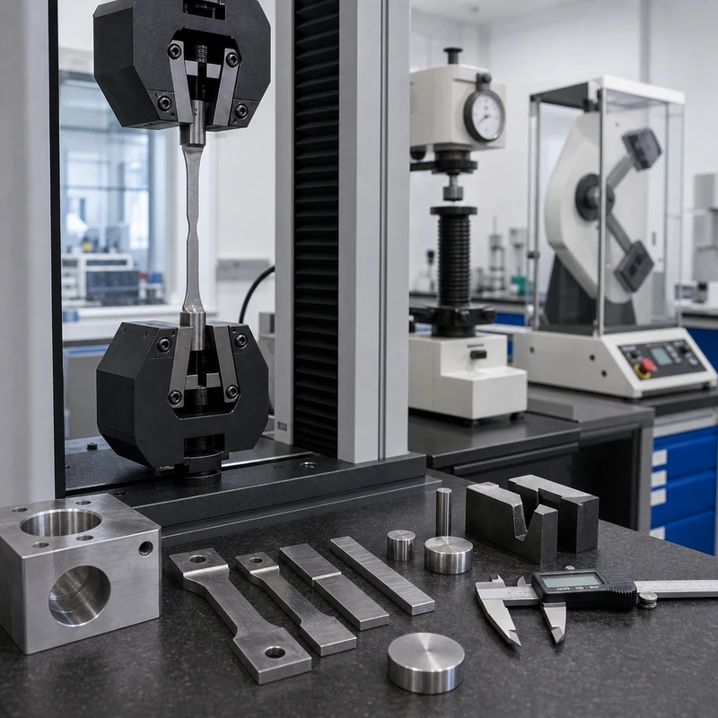
Categories
Blog Quality & Tolerances

Injection Molding Bubbles and Voids: An Evidence-Led Troubleshooting Guide

An apparent bubble in an injection-molded part may be a gas pocket or a shrinkage void. Identify the mechanism before changing the process. Gas-related defects can involve moisture, entrained air, or degradation. A shrinkage void forms when internal contraction is not adequately supplied with material during solidification. The same visual description does not justify the same correction.

Preserve Evidence Before Adjusting Settings

Retain defective and acceptable samples, identify the cavity, and record the material lot, startup condition, and current settings. Photograph the location relative to the gate and thick sections. Note whether the defect is repeatable in one location or scattered across the part.

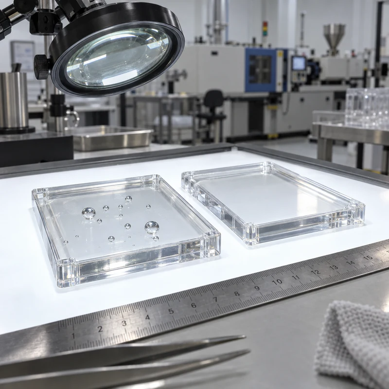
Transparent parts make internal defects easier to see, but a sound-looking exterior does not rule out an internal void. Where the application warrants it, use an approved inspection method such as controlled sectioning or suitable imaging. Do not heat unknown plastics with an open flame as an informal diagnostic test.

Observation Useful investigation What it does not prove alone
Pocket in the center of a thick section Packing effectiveness and cooling-related shrinkage That moisture can be ruled out without other evidence
Scattered pockets with surface streaking Resin condition, moisture, contamination, and melt history That drying is the only cause
Defect near a flow-ending region Fill pattern and vent condition That a higher injection speed will solve it
Problem after a prolonged machine interruption Residence time and material degradation That every subsequent shot is acceptable

BASF’s troubleshooting guidance distinguishes gas bubbles from voids and notes the connection between voids and thick, internally molten regions. Use such guidance as a diagnostic starting point, not a replacement for examining the actual part.

Check Resin Condition at the Point of Use

For moisture-sensitive grades, verify the material supplier’s drying requirements and the condition of material entering the machine. A dryer temperature display does not confirm the pellets have reached an acceptable moisture level. Review residence time in the dryer, loading practice, and exposure during transfer.

Keep resin grade, colorant, additives, and regrind proportion identifiable. If the defect appeared after a material change, retain samples from both conditions and check whether the change was approved. Drying an unfamiliar mixture more aggressively is not a substitute for establishing what material is being processed.

Review the Melt and Filling History

Inspect the approved processing window against actual operating conditions. Barrel settings, measured melt behavior, recovery conditions, and residence time must be considered together. A machine idle period or an unsuitable shot-to-barrel relationship can change the thermal history even when the temperature setpoints remain unchanged.

Air management also deserves a targeted review. Examine the filling sequence, vent condition, and melt preparation with the process engineer. Raising temperature or changing injection speed without identifying the mechanism may move the defect or introduce another one. The melt-temperature and material guide explains why processing advice must be grade-specific.

Document one controlled adjustment at a time when isolating a cause. Where variables interact, use an agreed experimental plan rather than informal simultaneous changes. Keep machine operation and mold intervention within trained personnel’s procedures.

Test Whether Packing Can Feed the Critical Region

If evidence indicates a shrinkage void, review whether the flow path remains capable of supplying the region during packing. A holding-pressure increase cannot compensate indefinitely for a gate that has already frozen. It can also create flash, residual stress, or dimensional changes elsewhere.

A qualified process study may examine part-weight response to hold time together with gate behavior and defect incidence. Record the stable process conditions and use the material supplier’s limits. Do not treat a single heavier part as proof that the internal defect has disappeared.

Address Geometry When the Process Window Is Too Narrow

Thick regions cool and shrink differently from adjacent thin sections. Protolabs’ moldability guidance identifies thick sections as a risk for sink and void formation. Evaluate whether a heavy boss or local mass can be cored while preserving its structural function. Review wall transitions, gate location, and the ability to feed the affected region with the tooling specialist.

Consider a hypothetical mounting boss attached to a thin housing wall. If the pocket repeatedly appears inside the boss, making the entire surrounding wall thicker may add material and create additional cooling problems. A revised boss and rib arrangement may be worth evaluating instead. That decision requires a new structural and molding review, not just a cosmetic repair.

Any machining of samples for diagnosis should preserve the defect evidence and sample identity. A machined prototype can help assess fit, but it cannot prove the molding process is free of internal voids.

Verify the Correction Beyond the First Good Shot

Define success before running the confirmation lot. Check the internal defect with the chosen method and verify that the correction has not created flash, sink, warpage, unacceptable dimensions, or a new cosmetic issue. Include all relevant cavities and agreed operating conditions.

  • Compare samples against the original defect map.
  • Record the final approved process and material condition.
  • Repeat the critical functional and dimensional checks.
  • Assess startup or interruption conditions where relevant.
  • Establish lot disposition and a reaction plan if the defect returns.

When requesting help with mechanical interfaces or prototype components, send MTSPi the drawing, defect photographs, and acceptance criteria through the technical inquiry page. Keep the molding-process investigation with the responsible molder and material specialists.

Frequently Asked Questions

Will increasing pressure always remove bubbles?

No. Gas pockets and shrinkage voids have different mechanisms, and pressure changes may introduce other defects. Diagnose first.

Are internal bubbles only a cosmetic issue?

No. Depending on location and application, internal defects can affect strength, sealing, or durability even if the surface looks acceptable.

Should every resin receive the same drying cycle?

No. Use the specific grade supplier’s requirements and verify the condition of material at the machine.

Does one clear sample prove the fix?

No. Confirm the agreed batch, cavity coverage, inspection method, and process conditions before releasing production.

Technical reference basis: BASF Injection Molding Troubleshooter and engineering-thermoplastic defect guidance; Protolabs moldability guidance on thick sections. Diagnostic examples are illustrative and do not replace resin-specific processing instructions.

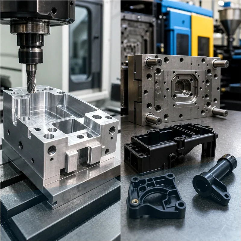
Categories
Blog Design, Cost & Sourcing

Medical Injection Molding Suppliers: An Evidence-Based Selection Guide

Choosing a medical injection molding supplier is an evidence exercise. A polished factory presentation does not establish that a particular production site can control your resin, tool, dimensions, contamination risks, and change history. The useful comparison is between the records each candidate can provide for the work you actually need.

Quick answer: Define the component’s function and acceptance criteria first. Screen suppliers for relevant quality-system scope, material traceability, tooling expertise, validation planning, and environmental controls. Then compare samples and documentation using the same drawing and test plan. Treat commercial price as one part of the decision.

Write a Project Brief Before Comparing Suppliers

A non-contact equipment cover, a fluid-path component, and an implantable component do not share the same requirements. Describe intended use, contact conditions where relevant, cleaning or sterilization exposure, assembly interfaces, quantities, and product life. Have the responsible quality and regulatory team define applicable obligations.

Include the exact resin grade or a controlled material-selection process. Define critical dimensions, appearance zones, packaging, and inspection methods. Suppliers cannot provide comparable proposals when each is making different assumptions about the scope.

An Evidence Matrix for Supplier Interviews

Area Evidence to request Follow-up question
Quality system Current certificate, site address, and scope where required Does the covered location perform this manufacturing step?
Material control Lot records, approved grades, storage and drying controls How is an unauthorized substitution prevented?
Tool and process DFM review, maintenance plan, sample process records How will cavity-to-cavity variation be evaluated?
Environment Defined controls and monitoring relevant to the component Where do parts travel after leaving the machine?
Measurement Inspection plan and suitable measurement methods Can the method reliably detect an out-of-limit part?
Changes Notification and approval procedure Which changes require customer approval before shipment?

Check Certification Scope Without Confusing It With Product Approval

A quality-system certificate can support supplier screening, but check its validity, scope, and manufacturing location. It does not establish approval of your device or prove that every process is suitable. Ask how the proposed work falls within the supplier’s controlled system and what records you will receive.

For U.S. finished-device manufacturers, FDA’s Quality Management System Regulation took effect on February 2, 2026 and incorporates ISO 13485:2016 by reference. Applicability depends on the organization’s role and product; a component supplier should not automatically be described as FDA approved. Confirm responsibilities for the actual supply arrangement.

Evaluate the Whole Handling Route

If controlled-environment molding is needed, map material entry, molding, trimming, inspection, assembly, and packaging. A clean machine area does not answer what happens during secondary handling. Define the contamination characteristics that matter and ask for the corresponding controls.

Keep environmental classification, product cleanliness, and sterility distinct. Establish the acceptance and verification approach with the responsible specialists. The cleanroom and standard molding comparison provides context for planning the production environment.

Make Validation Deliverables Part of the Quote

Discuss qualification and validation before issuing the tooling order. Agree on protocols, acceptance criteria, sample quantities, review responsibilities, and the records to be delivered. Installation, operational, and performance qualification may form part of the plan, depending on the process and applicable requirements.

Ask how the supplier will evaluate different cavities, material lots, and relevant process variation. A single attractive sample does not demonstrate sustained control. Where capability statistics are proposed, confirm that the measurement method and data set support the conclusion; do not accept a number detached from its method.

Review the Tooling and Drawing Together

Tool design affects gate vestiges, weld lines, ejector marks, parting lines, shrinkage, and assembly fit. Mark restricted areas on the drawing. Request an explanation of how critical features will be produced and measured, including the plan for correcting the tool after first samples.

For assemblies combining molded components with metal inserts or housings, define who owns the interface tolerances. Review the evaluation of precision component suppliers when the program also includes machined parts. Prototype fit checks can expose interface mistakes, but cannot establish production molding performance.

Set Traceability and Change Rules in Writing

Decide which records must connect the finished lot to the resin, colorant, tool, cavity, machine, inspection, and packaging batch. Define record retention and access. Use a sample record review during supplier assessment to check whether the trace can actually be followed.

  • Specify the policy for regrind and material substitutions.
  • Define approval of tool repairs that affect the component.
  • Include changes to subcontractors and production locations.
  • Agree how nonconforming lots will be segregated and reported.
  • Document the response and containment process for customer complaints.

Compare Commercial Terms After Technical Screening

Request separate prices for tooling, engineering work, qualification, routine production, inspection, and packaging. Clarify mold ownership, storage, maintenance, transfer documentation, and replacement inserts. Compare delivery commitments against realistic demand scenarios rather than only the smallest quoted unit price.

A practical selection method uses mandatory requirements first, then a documented scorecard. Do not average away a failed essential requirement with a low price. For two technically acceptable suppliers, compare the evidence quality, communication, capacity, and cost of sustaining the program.

Frequently Asked Questions

Does every medical component require a cleanroom?

Requirements depend on the component, intended use, subsequent processing, and acceptance criteria. Establish those requirements before specifying an environment.

Can a supplier certificate replace a product validation plan?

No. The certificate and the evidence for a particular product and process serve different purposes. Define the project-specific work and approval responsibilities.

What is the most useful first supplier meeting?

A review of one controlled drawing, its critical features, and the proposed evidence package. Concrete questions reveal more than a broad discussion of machine count.

This guide is a supplier-selection framework, not a statement that MTSPi holds a particular medical certification or operates a validated medical molding line.

Categories
Blog Manufacturing Process Comparisons Quality & Tolerances

Cleanroom Injection Molding vs Standard Molding: Key Differences for Precision Parts

Cleanroom Injection Molding vs Standard Molding: Key Differences for Precision Parts is a practical manufacturing question because the answer affects cost, lead time, material behavior, inspection, and the path from prototype to production. For MTSPi CNC customers, the key is not simply naming a process, but understanding how the process connects with machined parts, fixtures, tolerances, surface requirements, and final assembly.

This guide explains cleanroom injection molding vs standard molding from an engineering and purchasing point of view. It is written for product developers, mechanical engineers, sourcing teams, and buyers who need clear decisions rather than generic process descriptions.

Quick Answer

Use standard molding for general industrial, consumer, and enclosure components where normal factory cleanliness is acceptable. Use cleanroom molding when particle contamination, biological burden, optical clarity, or medical validation can affect product performance.

Key Differences at a Glance

Point Option A Option B
Environment Controlled air and particle limits Normal manufacturing environment
Parts Medical, diagnostic, optical, sensitive electronics Industrial covers, brackets, caps, housings
Documentation Higher traceability and validation records Standard production records
Cost Higher operating and monitoring cost Lower cost for ordinary parts
Risk focus Contamination, packaging, handling Dimensions, cycle stability, cosmetic quality

How the Process Choice Affects Real Parts

A manufacturing method should be selected around the feature that actually controls function. Cosmetic surfaces, hidden support features, threads, bores, sealing faces, heat-transfer areas, and assembly datums do not carry the same risk. When those requirements are mixed together without priority, quotes become inconsistent and production becomes harder to control.

The safest workflow is to define the part requirement first, then match the process. A printed prototype may answer shape questions, a molded sample may answer appearance questions, and a CNC machined sample may answer tolerance, material, and functional questions. Many successful projects use more than one method before the final design is locked.

Design and Manufacturing Considerations

  • Specify cleanliness requirements only when they are functional or regulatory needs.
  • Separate cosmetic requirements from contamination requirements on the drawing.
  • Confirm resin compatibility with sterilization, cleaning agents, and final assembly conditions.
  • Plan inspection for critical dimensions, flash, particulates, and packaging damage.
  • Coordinate CNC inserts, machined fixtures, or threaded metal parts before mold validation.

Cost, Lead Time, and Risk Factors

Cost is driven by setup, tooling, material, machine time, inspection, finishing, and revision risk. A low unit price is not always the lowest project cost if it creates rework later. For prototypes and low-volume orders, flexibility can be more valuable than a process with a lower theoretical unit cost.

  • Use standard materials and standard feature sizes when they do not weaken the design.
  • Separate critical tolerances from general dimensions so the supplier knows where to focus.
  • Confirm surface finish and cosmetic requirements before production begins.
  • Avoid late changes to mounting holes, connector openings, datum faces, and threaded features.
  • Send CAD files and 2D drawings together when tolerances, threads, or finishes matter.

Quality Checks Before Production

A good quality plan checks the features that influence assembly and performance. Depending on the part, this may include dimensional inspection, thread gauges, surface roughness, flatness, perpendicularity, burr control, coating thickness, visual appearance, and fit with mating parts.

When This Topic Matters for CNC Buyers

cleanroom injection molding vs standard molding matters when a team is comparing prototype routes, validating a design, replacing a weak supplier, or trying to reduce manufacturing cost without damaging function. The best choice is usually the process that answers the current engineering question with the least unnecessary risk.

MTSPi CNC Engineering Notes

MTSPi CNC supports precision CNC milling, turning, rapid prototyping, low-volume production, finishing, and inspection for custom parts. If your project uses molding, casting, welding, PCB assemblies, or 3D printing, CNC machining can still be important for datums, holes, threads, sealing faces, fixtures, and production-ready prototypes.

Frequently Asked Questions

Can this process replace CNC machining?

Sometimes it can replace CNC for non-critical geometry, but CNC is often still needed when tight tolerances, real engineering material, threads, flat sealing faces, or precise mating features are required.

What files help MTSPi CNC review a project?

STEP or STP files are useful for geometry. A 2D drawing is important for tolerances, materials, threads, surface finish, inspection requirements, and notes that are not obvious from the CAD model.

How do I reduce manufacturing risk?

Define critical features, avoid unnecessary tight tolerances, confirm material and finish requirements, and use prototypes to validate assembly before committing to higher-volume tooling or production.

Related MTSPi Resources

Categories
Blog CNC Materials Quality & Tolerances

Datums in CNC Machining: A Practical GD&T and Inspection Guide

A datum is an exact theoretical point, axis, or plane used to establish a measurement reference. A physical surface, hole, slot, or other feature on the part is a datum feature; inspection equipment or fixture contacts simulate that feature to establish the datum. Keeping those terms distinct helps a drawing translate into repeatable machining, assembly, and inspection.

For precision parts, MTSPi connects drawing intent to setup planning, multi-operation transfer, and quality assurance so the same functional references guide production and measurement.

Datum, Datum Feature, and Datum Feature Simulator

Term Meaning Example
Datum Perfect theoretical reference A plane derived from a mounting face
Datum feature Real part feature identified on the drawing The actual mounting face or locating bore
Datum feature simulator Equipment that contacts or represents the feature Surface plate, fixture pad, pin, mandrel, or CMM alignment

The real feature contains manufacturing variation. The datum is ideal. The simulator creates a repeatable relationship between the real part and the ideal reference used for evaluation.

How a Datum Reference Frame Constrains a Part

A common primary-secondary-tertiary scheme follows the 3-2-1 principle. The primary datum feature typically contacts three points and removes three degrees of freedom. The secondary feature contacts two points and removes two more. The tertiary feature uses one point to remove the final degree of freedom. Together they establish the datum reference frame named in a feature-control frame.

Datum order Typical role Degrees of freedom constrained
Primary (A) Stable functional base or broad surface Three
Secondary (B) Side surface, bore, or slot establishing direction Two
Tertiary (C) Final stop or clocking feature One

Why Datum Order Matters

A-B-C is not interchangeable with B-A-C. The first reference dominates how the part is oriented, while later references finish its location. Changing the order can change the measured position or orientation of features. Datum precedence should therefore reflect assembly function, not simply whichever surface is easiest for the machinist to touch.

Datums Across Design, Machining, and Inspection

Stage How datums are used Failure if inconsistent
Design Express functional relationships through GD&T A drawing may control the wrong interface
Process planning Choose workholding and operation sequence Tolerance stack grows across re-clamping
Machining Set work coordinates and transfer references Features shift between setups
Inspection Align CMM or gaging to the specified frame Good parts fail or bad parts pass
Assembly Locate mating components Fit, sealing, motion, or alignment problems

Choosing Functional Datum Features

  • Start with the surfaces or axes that locate the part in its real assembly.
  • Choose a primary feature that is stable, accessible, and large enough to establish orientation.
  • Use secondary and tertiary features that control functional direction and clocking.
  • Avoid rough cast, flexible, interrupted, or easily damaged features unless they truly represent function.
  • Consider how the features can be simulated in both production fixtures and inspection equipment.
  • Keep the datum scheme compatible with service loads, mating parts, and maintenance needs.

Common Datum Feature Types

Planar surfaces

Mounting faces are common primary datum features because they can provide stable orientation. Flatness and contact distribution still matter.

Holes and cylindrical features

A bore can establish a datum axis, while a pin pattern can locate and clock a part. Clearance, material boundary modifiers, and simulator type affect how the frame is established.

Slots and tabs

Center planes derived from width features can locate a part while allowing controlled movement in another direction.

Datum targets

Targets define selected points, lines, or areas and are useful for castings, forgings, sheet structures, and irregular surfaces where full-surface contact would be unstable.

Datums Versus Machine Zero

The machine coordinate system and work offset are programming tools. A drawing datum is a design and inspection reference. A programmer may align a work offset with a datum for convenience, but they are not automatically the same. Setup documentation should explain the transformation so dimensions remain traceable through every operation.

Multi-Setup and 5-Axis Parts

Complex parts often cannot retain the functional datums in one clamping. Process planners may create temporary machining references, precision soft jaws, or qualified fixture features. The important point is to control the transfer back to the drawing reference frame. On 5-axis CNC machining projects, a strong datum plan can reduce re-clamping, but inspection still has to reconstruct the specified frame correctly.

Frequent Datum Mistakes

  • Labeling a theoretical plane as though it were the physical surface.
  • Selecting cosmetic or convenient faces instead of functional interfaces.
  • Using unstable features that rock or deform in a fixture.
  • Failing to preserve datum relationships across secondary operations.
  • Inspecting from shop-friendly references that differ from the drawing.
  • Over-constraining a part with incompatible fixture contacts.
  • Omitting datum order or material-boundary requirements where they matter.

Drawing Review Checklist

  • Do A, B, and C reflect how the part mates and carries load?
  • Can each datum feature be reached by the fixture and CMM probe?
  • Are flexible or unfinished surfaces controlled appropriately?
  • Does each positional or orientation tolerance reference the intended frame?
  • Are datum targets, basic dimensions, and feature-control frames unambiguous?
  • Can the machining sequence preserve or accurately re-establish the frame?

FAQ

Can a hole be a datum?

Yes. The hole is the datum feature, and its derived axis can establish the datum.

What do Datum A, B, and C mean?

They identify datum features in precedence order: primary, secondary, then tertiary.

Does every CNC part need three datums?

No. The reference structure should be only as complex as the functional geometry requires.

Can an inspection setup use different datums?

Intermediate checks may use process references, but final acceptance must evaluate requirements from the datum reference frame specified on the drawing.

Related MTSPi Resources

Categories
Blog Industries & Applications Quality & Tolerances

How to Evaluate Swiss CNC Machining Manufacturers in China

Swiss-type CNC machining is one of the most useful processes for small turned parts that need length, fine details, tight runout control, and repeatable production. China remains an important sourcing region for this work, but a buyer should not choose a supplier from a ranked name list alone. The real question is whether the shop can control bar-fed machining, guide-bushing support, live tooling, inspection, materials, finishing, and communication for your specific component. MTSPi supports Swiss-type machining and broader CNC turning service for precision shafts, pins, connectors, bushings, fasteners, and miniature mechanical parts.

What Makes Swiss-Type Machining Different

A Swiss-type lathe supports the bar close to the cutting tool, so the unsupported cutting length is very short. That setup is especially valuable for slender parts that would deflect on a conventional turning center. Many Swiss machines also combine turning, drilling, milling, slotting, thread cutting, and back-working in one cycle, which can reduce secondary operations when the part is designed well.

Capability Why It Matters Parts That Benefit
Guide-bushing support Reduces deflection on long and small-diameter workpieces Pins, shafts, needles, sleeves, miniature spacers
Live tooling Adds cross holes, flats, slots, and milled features in the same setup Connectors, medical-style components, sensor hardware
Bar-fed production Improves repeatability and cycle efficiency for small parts Fasteners, bushings, fittings, electrical contacts
Back-working Completes rear-side features after part-off Threaded ends, counterbores, chamfers, face details

How to Evaluate Swiss CNC Machining Manufacturers in China

The best supplier for a Swiss-machined part is not always the shop with the largest equipment list. Start with the drawing, the material, the annual volume, and the inspection requirement. Then compare suppliers by how clearly they explain the process plan and the risks.

Evaluation Area What to Confirm Buyer Risk if Ignored
Machine fit Bar diameter range, guide-bushing setup, live-tool axes, sub-spindle capability, and part-off strategy The part may require extra setups, higher cost, or unstable tolerance control
Tolerance control Expected process capability for diameter, length, runout, concentricity, threads, and small milled features A nominally precise shop may still miss the features that matter most
Material experience Stainless steel, titanium, aluminum, brass, copper alloys, engineering plastics, and difficult-to-machine grades Tool wear, burrs, heat, and surface finish can change the real lead time
Inspection method Micrometers, pin gauges, optical measurement, CMM, surface roughness checks, and documented first-article reports Quality evidence may not match the drawing requirement
Production control Tool-life rules, lot traceability, revision control, deburring standard, cleaning, and packaging Prototype success may not repeat across production batches
Engineering communication DFM questions, drawing markups, tolerance alternatives, finish notes, and change tracking Ambiguous requirements can turn into late rework

When Swiss-Type Machining Is the Right Process

Swiss machining is strongest when the part is small, slender, highly detailed, and expected to repeat. It is not automatically the best answer for every turned component. A short, simple bushing may be cheaper on a standard turning center. A large shaft may exceed the bar capacity. A prismatic part may belong on a milling platform or a mill-turn machine.

Part Condition Swiss-Type Fit Reason
Long diameter-to-length ratio Strong fit Guide-bushing support helps control bending and vibration
Tiny cross holes or milled flats Strong fit Live tooling can finish multiple features before part-off
Very short simple spacer Possible but not always economical Conventional turning may be faster and simpler
Large diameter component Usually poor fit Swiss machines are optimized around small bar stock
High-volume miniature part Strong fit Bar feeding and cycle consolidation can improve consistency

Materials Commonly Used for Swiss-Machined Parts

Material choice affects cutting stability, burr formation, tool wear, finish, and inspection. For material comparisons, review MTSPi’s CNC machining materials library before locking the drawing note. Swiss-type machining can handle many metals and plastics, but each grade needs a realistic plan.

Material Typical Use Manufacturing Note
Stainless steel Medical-style hardware, shafts, pins, fasteners, corrosion-resistant components Can work harden; tool condition and burr control matter
Titanium Lightweight high-strength components and demanding assemblies Heat control and sharp tooling are critical
Aluminum Light precision parts, housings, sleeves, electronics hardware Machines efficiently but needs clear cosmetic and anodizing notes
Brass Fittings, contacts, bushings, inserts, connectors Excellent machinability, with cleaning and tarnish expectations defined
Engineering plastics Insulators, low-friction spacers, lightweight precision parts Thermal movement and clamping distortion need attention

Inspection Questions Buyers Should Ask

  • Which dimensions will be checked in-process, and which will be checked after part-off?
  • How will runout, concentricity, thread fit, and small cross features be measured?
  • Does inspection happen before or after passivation, anodizing, plating, or cleaning?
  • Can the supplier provide a first-article report with actual measured values?
  • How are tool wear, burr growth, and dimensional drift controlled during repeat production?
  • What packaging prevents tiny parts from mixing, scratching, or damaging thread starts?

Design Details That Improve Swiss Machining Results

Swiss machining is precise, but it still benefits from practical DFM. Overly sharp internal corners, unrealistic surface finish notes, deep miniature holes, thin unsupported features, and excessive tolerance stacking can increase cost or reduce repeatability. If a feature is functional, mark it clearly. If a tight tolerance is only inherited from a template, loosen it before quoting.

Design Area Better Practice Why It Helps
Diameters Identify critical fits separately from noncritical stock-removal surfaces Keeps inspection effort focused on function
Threads Define thread standard, class, gauge requirement, and lead-in chamfer Prevents assembly issues in miniature components
Cross holes Confirm position tolerance and burr expectations Small intersecting holes often need special deburring control
Surface finish Apply roughness requirements only where they matter Avoids unnecessary cycle time and polishing risk
Part length Discuss cutoff burr, back-face finish, and sub-spindle support Controls the final end condition

RFQ Package for Comparing Suppliers

A complete RFQ makes supplier comparison much easier. Send the same information to each shop so price, lead time, inspection, and risk can be compared on equal assumptions.

RFQ Item Recommended Detail
3D model STEP file with the latest revision
2D drawing Datums, tolerances, threads, surface finish, notes, and critical dimensions
Material Grade, standard, temper or condition, and certificate requirement
Quantity Prototype order, batch size, annual volume, and release schedule
Finish Passivation, anodizing, plating, polishing, cleaning, color, and masking notes
Inspection First-article report, CMM or optical report, gauge checks, sampling level, and measurement format
Packaging Bagging, tray packing, anti-scratch protection, label format, and lot separation

When MTSPi Can Be a Practical Supplier Option

MTSPi can review Swiss-type turned parts, standard turned parts, milled features, and finishing requirements as one manufacturing package. For projects that involve small precision components, related capabilities may include Swiss-type machining, CNC turning, CNC milling, surface treatment, and quality assurance. Send the CAD model, drawing, material, quantity, tolerance notes, and inspection expectations so the manufacturing route can be reviewed before quoting.

Related MTSPi Resources

FAQ

What is Swiss CNC machining best for?

It is best for small, slender, complex turned parts such as pins, shafts, connectors, screws, sleeves, bushings, terminals, and miniature precision components.

Is Swiss-type machining always more accurate than standard turning?

Not always. It can be more stable for long and small-diameter parts, but accuracy still depends on machine setup, tooling, material, inspection, and process control.

What tolerances can Swiss machining hold?

The practical tolerance depends on the feature, material, part length, machine condition, tooling, and inspection method. Buyers should ask for realistic capability on the actual critical dimensions rather than a generic tolerance claim.

How do I compare Swiss CNC machining manufacturers in China?

Compare machine fit, bar capacity, live tooling, material experience, first-article reporting, tolerance control, deburring, finishing coordination, packaging, communication, and repeat-production control.

Categories
Blog CNC Materials Quality & Tolerances

What Is Mechanical Testing? Methods, Data, and CNC Part Applications

Mechanical testing evaluates how a material, coupon, or finished component behaves under controlled load, impact, temperature, wear, or repeated stress. For CNC machined parts, it helps engineering teams confirm whether a selected metal or plastic can meet strength, durability, and safety requirements in real service.

Mechanical testing is different from routine dimensional inspection. A caliper, micrometer, or CMM checks size and geometry; a mechanical test checks performance. MTSPi supports precision projects with quality assurance, material review, dimensional inspection, and documentation planning for custom machined parts.

What Mechanical Testing Measures

Property What It Shows Why It Matters for CNC Parts
Tensile strength Resistance to pulling force before fracture Useful for brackets, shafts, housings, fastened joints, and load-bearing parts
Yield strength Stress level where permanent deformation begins Helps prevent bent, distorted, or misaligned components
Hardness Resistance to indentation and local wear Important for sliding surfaces, tooling interfaces, pins, bushings, and wear parts
Impact toughness Ability to absorb sudden energy Relevant for parts exposed to shock, handling damage, or low-temperature service
Fatigue behavior Resistance to repeated cyclic loading Critical for moving assemblies, robotics, aerospace hardware, and vibration-prone parts

Common Mechanical Test Methods

Tensile testing

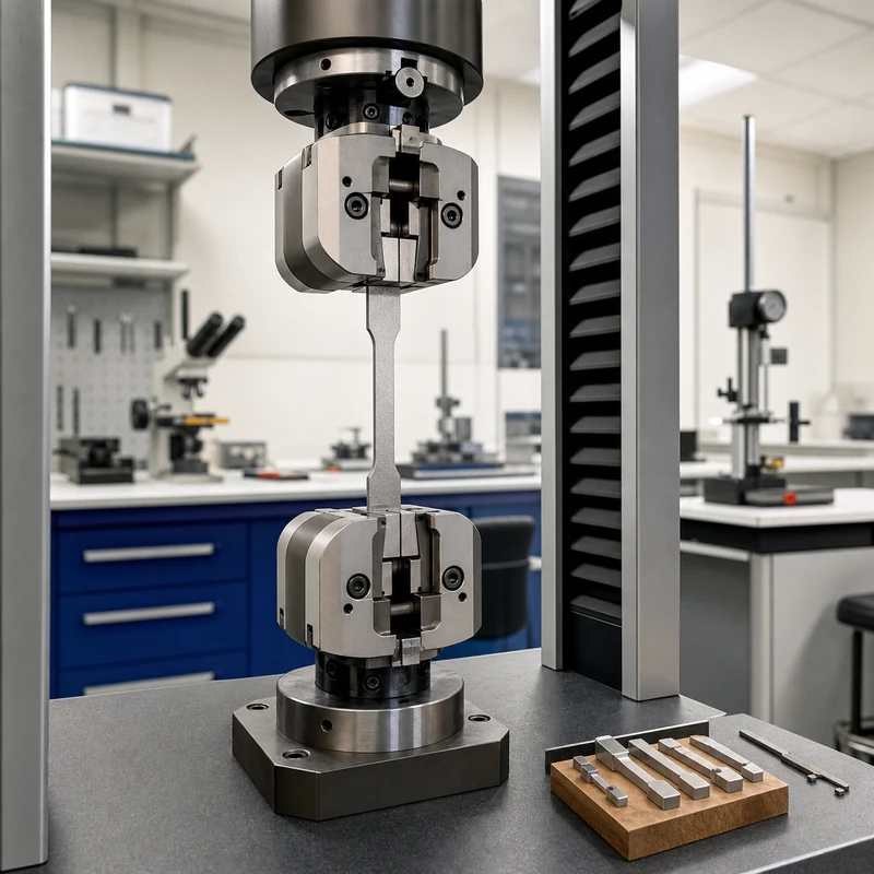
A prepared sample is pulled until it yields and eventually breaks. The resulting stress-strain curve can show elastic behavior, yield point, tensile strength, elongation, and fracture response. For production parts, tensile data is often supplied through material certificates rather than testing every machined component.

Compression and bending tests

Compression testing checks how a material behaves under squeezing load, while bend testing evaluates ductility and resistance to cracking. These methods are useful when parts see clamp loads, forming forces, press fits, or structural bending in service.

Hardness testing

Rockwell, Brinell, Vickers, and microhardness methods estimate resistance to indentation. Hardness checks are common after heat treatment, surface hardening, or material substitution, especially for steels, tool steels, stainless steels, and wear-focused components.

Impact and fracture tests

Impact testing measures how much energy a material absorbs during a fast strike. Fracture-related testing is useful when brittle failure, low-temperature exposure, or safety-critical loading must be understood before a design is released.

Fatigue testing

Fatigue testing repeats load cycles until cracks initiate or failure occurs. It is important for parts that rotate, vibrate, flex, or see repeated assembly loads. Fatigue risk is affected by material, surface finish, corners, threads, inclusions, and machining marks.

Mechanical Testing vs Dimensional Inspection

Check Type Primary Question Typical Tools
Dimensional inspection Does the part match the drawing size and geometry? CMM, micrometers, calipers, height gauges, pins, optical measurement
Mechanical testing Will the material or part perform under load or use conditions? Tensile frames, hardness testers, impact testers, fatigue rigs, environmental chambers
Surface and finish checks Is the surface suitable for wear, sealing, adhesion, or appearance? Profilometers, visual standards, coating-thickness gauges

When Buyers Should Request Mechanical Testing

  • The part is load-bearing, safety-related, or used in aerospace, medical, robotics, energy, or industrial machinery.
  • The drawing requires a material standard, heat treatment condition, hardness range, or certified test report.
  • A new material grade is being substituted for cost, supply, weight, or corrosion reasons.
  • The part has thin sections, stress concentrations, threads, press fits, or surfaces exposed to repeated load.
  • A prototype failed during use and the team needs to separate material issues from design or machining issues.

How Machining Can Affect Test Results

CNC machining can influence part performance through surface finish, residual stress, sharp internal corners, burrs, tool marks, heat input, and grain direction in stock material. A strong material can still fail early if the design creates high local stress or if finishing leaves a poor surface at a critical location.

  • Use generous internal radii where loads change direction.
  • Avoid unnecessary sharp notches around highly stressed features.
  • Specify surface roughness where fatigue, sealing, or sliding behavior matters.
  • Confirm heat treatment and hardness requirements before machining begins.
  • Keep material certificates tied to the correct lot and drawing revision.

Material Families and Testing Priorities

Material Family Common Tests Design Note
Aluminum alloys Tensile, hardness, fatigue, corrosion checks Useful for lightweight parts, but thread and fatigue design need care
Stainless steel Tensile, hardness, corrosion, impact where needed Good corrosion resistance, with grade-specific machinability and finishing behavior
Titanium Tensile, fatigue, fracture, hardness Strong lightweight option where heat control and surface condition are important
Engineering plastics Tensile, flexural, impact, creep, temperature exposure Performance depends strongly on temperature, moisture, and load duration

How MTSPi Uses Test Requirements

When a drawing includes mechanical testing or certification requirements, MTSPi reviews them during quoting so material choice, machining sequence, finishing, and inspection records line up with the final use. Share your CAD model, 2D drawing, material standard, required report type, and quantity through the contact page.

Related MTSPi Resources

FAQ

Is mechanical testing required for every CNC part?

No. Many parts only need dimensional inspection. Mechanical testing is most useful when material performance, certification, safety, or high-load service matters.

Can finished CNC parts be mechanically tested?

Sometimes. Many tests use standardized coupons, but finished parts can be tested in fixtures when the goal is to validate real assembly behavior.

Categories
Blog Quality & Tolerances

What Is CMM Inspection? Complete Guide to Coordinate Measuring Machines for CNC Parts

Quick answer: CMM inspection uses a coordinate measuring machine to measure part features in three-dimensional space. It checks dimensions, hole positions, profiles, flatness, perpendicularity, true position, datums, and GD&T requirements. For CNC machined parts, CMM inspection is most useful when features are tight, complex, datum-based, or critical to assembly.

What Is a CMM?

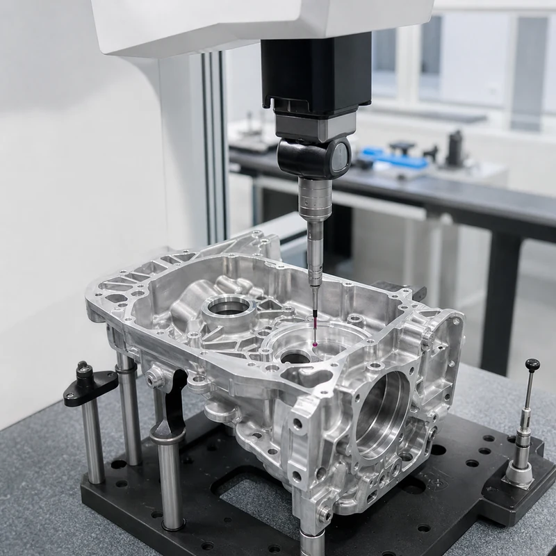
A CMM, or coordinate measuring machine, is an inspection system that measures points on a part using a probe or sensor. The machine records X, Y, and Z coordinates and compares them with the drawing or CAD model. This allows inspectors to verify whether a machined part is within tolerance.

CMM inspection is common for precision CNC parts because many features cannot be judged reliably with calipers alone. Hole patterns, datum relationships, true position, perpendicularity, flatness, and complex profiles need a measurement method that understands the part in 3D space.

What CMM Inspection Can Measure

Feature What CMM checks Why it matters
Hole position Location relative to datums or other holes Controls assembly alignment
Flatness Variation across a surface Important for sealing, mounting, and contact faces
Perpendicularity Angle relationship between axes or surfaces Important for housings, brackets, and fixtures
Profile Deviation from CAD surface or drawing profile Useful for complex milled geometry
True position GD&T-controlled feature location Common for precision hole patterns
Distance and size Lengths, widths, diameters, depths Confirms basic drawing dimensions

How CMM Inspection Works

First, the inspector reviews the drawing and identifies datums, critical features, tolerance zones, and measurement requirements. The part is cleaned and fixtured so it sits in a repeatable position. The CMM then touches or scans selected points. Software compares the measured data with the nominal CAD or drawing values and creates a report.

For repeat production, a CMM program can be saved and reused. This helps measure the same features consistently across batches. For first article inspection, the report may include a broader set of dimensions to validate the initial production process.

CMM Inspection vs Manual Inspection

Inspection method Best for Limitations
Calipers Quick checks of general dimensions Limited for complex geometry and high precision
Micrometers Accurate outside diameters and thickness Feature access and operator method matter
Pin / plug gauges Hole size and fit checks Does not fully describe position or geometry
Thread gauges Internal or external thread fit Does not measure all thread geometry
CMM Datum-based geometry, GD&T, complex parts More time and cost than simple manual checks

When Should Buyers Request CMM Inspection?

  • The part has tight tolerance hole patterns.
  • The drawing uses GD&T such as true position, profile, flatness, or perpendicularity.
  • The part must fit into a larger assembly with little adjustment.
  • The part has multiple machined sides or complex surfaces.
  • The order requires first article inspection or documented quality records.
  • The cost of failure is higher than the cost of measurement.

What Should a CMM Report Include?

A useful CMM report should include part name, drawing number, revision, inspection date, measured features, nominal values, tolerance limits, actual measurements, deviation, pass/fail result, datum reference, and inspector notes. For regulated or high-value projects, material certificate, finish confirmation, and first article documentation may also be needed.

GD&T, Datums, and CMM Inspection

GD&T gives more precise control over how features relate to each other. A hole may pass a simple diameter check but still fail true position if it is not located correctly from the datums. CMM inspection is strong in this situation because it can evaluate the feature within a coordinate system based on the drawing’s datum structure.

If the datum structure is unclear, inspection becomes uncertain. Buyers should make sure the drawing identifies primary, secondary, and tertiary datums where needed. For CNC suppliers, clear datums also help plan workholding and machining sequence.

CMM Inspection for CNC Milling and Turning

For CNC milled parts, CMM inspection is useful for hole patterns, pockets, flatness, profiles, and multi-side relationships. For CNC turned parts, it can support checks for bores, faces, grooves, concentric relationships, cross holes, and secondary milled features. It works best when the drawing clearly separates critical and non-critical dimensions.

How to Reduce Inspection Cost Without Increasing Risk

  • Identify critical dimensions instead of requiring a full report for every feature.
  • Use general tolerance notes for non-critical dimensions.
  • Provide CAD and drawing files together.
  • Define datum structure clearly.
  • Use gauges for simple features and CMM for features that need 3D relationships.
  • Agree on sampling quantity before production.

FAQ

Is CMM inspection required for every CNC part?

No. Many simple parts can be checked with calipers, micrometers, gauges, or visual inspection. CMM is most valuable for precision, complex, or GD&T-controlled parts.

Can CMM inspect threads?

CMM can check thread location and related geometry, but thread fit is usually checked with go/no-go thread gauges.

What is the difference between CMM and FAI?

CMM is a measurement method. First article inspection is a broader process that may include CMM measurements, material checks, finish checks, and documentation.

Does CMM inspection add lead time?

Yes, it can add inspection time, especially for complex reports. But it can reduce risk when parts are expensive or assembly-critical.

What files help CMM inspection?

A 2D drawing with tolerances and datums is essential. A 3D CAD model can help with programming and profile comparison.

Need inspection support for precision parts?

Send your drawing, GD&T notes, CAD file, and critical dimensions. MTSPi can review the right inspection method before quoting.

Contact MTSPi for CNC inspection support

Conclusion

CMM inspection helps confirm that CNC machined parts match the drawing in three-dimensional space. It is most useful for complex geometry, datum-based tolerances, first article inspection, and parts where assembly risk is high.

Categories
Blog Quality & Tolerances

Mechanical Testing Guide: Methods, Benefits, and Manufacturing Use

Mechanical testing measures how a material or finished part behaves under force, load, impact, bending, wear, or repeated stress. For machined components, testing helps confirm that the selected material and manufacturing route can meet real service conditions, not just drawing dimensions.

In a complete manufacturing plan, mechanical testing works alongside dimensional inspection, material certification, and quality assurance controls. It is especially useful for load-bearing parts, safety-related assemblies, and components that operate under heat, vibration, or fatigue.

Why Mechanical Testing Matters

  • It verifies strength, ductility, hardness, and other performance properties.
  • It helps compare candidate materials before production.
  • It supports failure analysis when parts crack, deform, or wear too quickly.
  • It provides objective data for quality documents and customer approval.

Common Mechanical Testing Methods

Test Method What It Measures Typical Use
Tensile testing Strength, yield point, elongation Material qualification and comparison
Hardness testing Resistance to indentation Heat treatment checks and wear expectations
Impact testing Energy absorbed during fracture Low-temperature or shock-load applications
Fatigue testing Life under repeated loading Rotating, vibrating, or cyclic-load components
Compression testing Behavior under crushing force Spacers, blocks, structural parts
Bend testing Ductility and crack resistance Sheet, welds, and formed parts

Testing Before and After Machining

Material testing may happen before machining to confirm that incoming stock meets specification. Finished-part testing may happen after machining, heat treatment, coating, or assembly. For example, a stainless shaft might need hardness verification after heat treatment, while an aluminum bracket may need dimensional checks after surface finishing to confirm coating buildup has not affected assembly features.

How to Choose the Right Test

The correct test depends on how the component will fail if something goes wrong. A cosmetic cover does not need the same test plan as a load-bearing aerospace bracket. Engineers should connect each test to a functional requirement, such as clamp load, wear life, fracture resistance, or dimensional stability.

  • Define the service environment: temperature, load, chemicals, and vibration.
  • Identify critical material properties from the design.
  • Choose a recognized test method when documentation is required.
  • Plan sample size and acceptance criteria before production starts.

Mechanical Testing and CNC Part Quality

CNC machining controls shape, tolerance, and finish, but it does not automatically guarantee material performance. When both geometry and material behavior matter, combine machining with certificates, inspection records, and test results. MTSPi can help align machining, inspection, and documentation for production projects.

Related MTSPi Resources

FAQ

Does every CNC part need mechanical testing?

No. Testing should match the risk, function, material, and customer requirements of the part.

Is hardness testing destructive?

Some hardness tests leave small marks, while others are more suitable for finished surfaces. The method should be chosen carefully.

Can mechanical testing replace dimensional inspection?

No. It answers different questions. Mechanical testing checks performance properties, while dimensional inspection checks geometry.

Request A Quote

We'll Send You Back with Price Immediately!

DEC 1-31

XMAS SPECEIL

Up to

40% off

Mechanical Testing Guide: Methods, Benefits, and Manufacturing Use

We'll Send You Back with Price Immediately!