

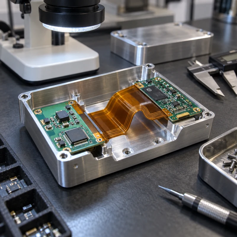
A rigid-flex PCB combines rigid circuit sections with flexible polyimide interconnects in one laminated assembly. It can replace connectors and wire harnesses, save space, reduce assembly steps, and support controlled three-dimensional packaging.
The advantages come with stricter mechanical rules. Bend radius, copper direction, coverlay, layer transitions, stiffeners, enclosure clearances, and assembly sequence must be coordinated early.
Quick Answer
Use rigid-flex when packaging, reliability, weight, or connector reduction justifies the added design and fabrication complexity. Keep bends away from rigid transitions, vias, solder joints, and sharp enclosure edges. Validate the folded state with production-intent stackup and housing geometry.
Key Engineering Factors
| Factor | Practical effect | Control method |
|---|---|---|
| Bend radius | Too small a radius strains copper and dielectric | Set radius from stackup and flex type |
| Rigid-flex transition | Stress concentrates at the boundary | Use controlled transition and strain relief |
| Copper layout | Traces across bend can fatigue | Route perpendicular to bend and stagger layers |
| Enclosure clearance | Pinching or rubbing damages flex | Model dynamic and assembled envelopes |
| Assembly sequence | Fold order can load components | Document fixtures and installation steps |
How Rigid-Flex Construction Works
Rigid sections commonly use FR4 while flexible sections use polyimide and rolled or electrodeposited copper. Coverlay protects flex conductors. Adhesives, no-flow prepreg, stiffeners, and plated features are selected around stackup and reliability.
Static vs Dynamic Flexing
A static flex bends during assembly and then remains in position. A dynamic flex moves repeatedly in service and needs larger radii, suitable copper, balanced layers, controlled neutral axis, and fatigue validation.
Bend-Area Design Rules
Keep pads, vias, component terminations, abrupt width changes, and rigid edges away from active bends. Curved trace transitions and staggered conductors reduce stress concentration.
- Route traces perpendicular to bend axis
- Avoid copper corners and teardrop discontinuities in flex zones
- Use hatched planes when solid copper makes the section too stiff
- Define bend direction and final folded angle
- Confirm minimum radius with the fabricator
Mechanical Enclosure Integration
The housing must support rigid boards while allowing the flex to follow a natural curve. Avoid sharp machined edges, screw interference, compression, and excessive free length. Include assembly access and serviceability.
- Import the PCB STEP model into enclosure CAD
- Model the flex in its assembled state
- Add edge radii and protective clearances
- Support heavy connectors on rigid sections
- Check thermal and EMI contact intentionally
Stackup and Fabrication Communication
Provide the controlled stackup, impedance needs, copper weights, materials, surface finish, stiffeners, coverlay openings, controlled-depth features, and test requirements. Ask the fabricator to review the design before layout release.
Assembly and Inspection
Rigid-flex assemblies may require dedicated carriers, fold fixtures, and handling instructions. Inspect conductor continuity, finished outline, plating, coverlay registration, impedance, solder quality, and the final folded assembly.
CNC-Machined Housing Considerations
CNC housings provide strong mounting, shielding, sealing, and thermal paths. Tolerance stacks must include board outline, connector position, standoff height, coating, gasket compression, and flex clearance.
Frequently Asked Questions
How many times can a rigid-flex PCB bend?
Static designs may only bend during assembly; dynamic life depends on stackup, radius, copper, stroke, environment, and testing.
Can vias be placed in the bend area?
They should generally be kept outside active bends because plated holes create stiffness and stress concentration.
Why use rigid-flex instead of cables?
It can reduce connectors, assembly labor, space, weight, and potential connection failures when the program justifies the higher fabrication complexity.