

Categories
Blog CNC Materials Manufacturing Process Comparisons

Aluminum Gravity Casting: Process, Design Rules, and CNC Finishing Options

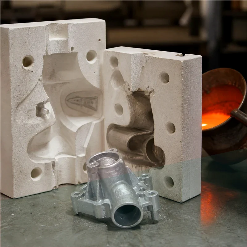
Aluminum Gravity Casting: Process, Design Rules, and CNC Finishing Options is a practical manufacturing question because the answer affects cost, lead time, material behavior, inspection, and the path from prototype to production. For MTSPi CNC customers, the key is not simply naming a process, but understanding how the process connects with machined parts, fixtures, tolerances, surface requirements, and final assembly.

This guide explains aluminum gravity casting from an engineering and purchasing point of view. It is written for product developers, mechanical engineers, sourcing teams, and buyers who need clear decisions rather than generic process descriptions.

Quick Answer

Use aluminum gravity casting for medium-volume aluminum parts with cast-friendly geometry and functional strength needs. Use CNC finishing for critical dimensions that casting alone cannot hold reliably.

Key Differences at a Glance

Point Option A Option B
Shape creation Mold forms near-net geometry Material is removed from stock
Best use Repeated cast shapes with moderate complexity Tight features, prototypes, precision interfaces
Tolerance Moderate before machining Tight when setup is controlled
Surface Cast texture or finished after processing Machined texture or specified finish
Tooling Mold required Fixtures and cutting tools required

How the Process Choice Affects Real Parts

A manufacturing method should be selected around the feature that actually controls function. Cosmetic surfaces, hidden support features, threads, bores, sealing faces, heat-transfer areas, and assembly datums do not carry the same risk. When those requirements are mixed together without priority, quotes become inconsistent and production becomes harder to control.

The safest workflow is to define the part requirement first, then match the process. A printed prototype may answer shape questions, a molded sample may answer appearance questions, and a CNC machined sample may answer tolerance, material, and functional questions. Many successful projects use more than one method before the final design is locked.

Design and Manufacturing Considerations

  • Keep wall thickness transitions gradual to reduce shrink and hot spots.
  • Add machining allowance on critical surfaces.
  • Avoid isolated heavy sections unless feeding and cooling are designed.
  • Define which surfaces are as-cast and which are CNC machined.
  • Plan datum strategy before mold tooling is finalized.

Cost, Lead Time, and Risk Factors

Cost is driven by setup, tooling, material, machine time, inspection, finishing, and revision risk. A low unit price is not always the lowest project cost if it creates rework later. For prototypes and low-volume orders, flexibility can be more valuable than a process with a lower theoretical unit cost.

  • Use standard materials and standard feature sizes when they do not weaken the design.
  • Separate critical tolerances from general dimensions so the supplier knows where to focus.
  • Confirm surface finish and cosmetic requirements before production begins.
  • Avoid late changes to mounting holes, connector openings, datum faces, and threaded features.
  • Send CAD files and 2D drawings together when tolerances, threads, or finishes matter.

Quality Checks Before Production

A good quality plan checks the features that influence assembly and performance. Depending on the part, this may include dimensional inspection, thread gauges, surface roughness, flatness, perpendicularity, burr control, coating thickness, visual appearance, and fit with mating parts.

When This Topic Matters for CNC Buyers

aluminum gravity casting matters when a team is comparing prototype routes, validating a design, replacing a weak supplier, or trying to reduce manufacturing cost without damaging function. The best choice is usually the process that answers the current engineering question with the least unnecessary risk.

MTSPi CNC Engineering Notes

MTSPi CNC supports precision CNC milling, turning, rapid prototyping, low-volume production, finishing, and inspection for custom parts. If your project uses molding, casting, welding, PCB assemblies, or 3D printing, CNC machining can still be important for datums, holes, threads, sealing faces, fixtures, and production-ready prototypes.

Frequently Asked Questions

Can this process replace CNC machining?

Sometimes it can replace CNC for non-critical geometry, but CNC is often still needed when tight tolerances, real engineering material, threads, flat sealing faces, or precise mating features are required.

What files help MTSPi CNC review a project?

STEP or STP files are useful for geometry. A 2D drawing is important for tolerances, materials, threads, surface finish, inspection requirements, and notes that are not obvious from the CAD model.

How do I reduce manufacturing risk?

Define critical features, avoid unnecessary tight tolerances, confirm material and finish requirements, and use prototypes to validate assembly before committing to higher-volume tooling or production.
Related MTSPi Resources

Categories
Blog CNC Machining Basics

Sheet Metal Hemming: Process, Types, Advantages, and Design Rules

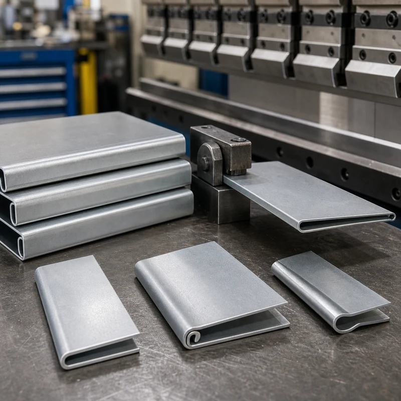
Sheet metal hemming folds an edge back onto itself to create a safer, stronger, and cleaner border. It is common in panels, covers, doors, automotive parts, enclosures, and consumer products.

A hem can remove sharp edges, improve stiffness, hide a raw cut edge, and help two sheets join together. The process must be planned with bend radius, material thickness, grain direction, and tooling clearance in mind.

Quick Guide to Sheet Metal Hemming

Item Purpose Manufacturing Note
Open hem Edge is folded but leaves a small gap Useful when material may crack if flattened
Closed hem Edge is folded flat Clean appearance but higher forming stress
Teardrop hem Rounded internal gap Good for harder or thicker materials
Rope hem Rolled circular edge Adds stiffness and safer handling

Process Selection Notes

The best process depends on material, geometry, tolerance, quantity, surface finish, heat effects, burr requirements, and whether the part needs secondary machining or finishing.

  • Match the process to the material and geometry.
  • Confirm critical dimensions before quoting.
  • Plan finishing and inspection before production.
  • Use prototypes to validate fit when the assembly risk is high.

Common Applications

Sheet Metal Hemming is relevant for prototypes, custom components, fixtures, low-volume manufacturing, maintenance parts, and engineering projects where function, cost, and lead time must be balanced.

Cost Factors

Cost usually depends on setup time, material price, number of operations, tool access, tolerance requirements, surface finish, inspection depth, and batch quantity.

Design and Sourcing Notes

The safest design approach is to define the part’s function first, then assign tolerances only where they affect assembly, movement, sealing, safety, or long-term performance.

  • Avoid unnecessary tight tolerances on non-critical surfaces.
  • Keep internal corners, hole depths, wall thickness, and tool access realistic.
  • Call out cosmetic surfaces separately from functional surfaces.
  • Include material, finish, quantity, and inspection notes in the RFQ package.

Quality Checks That Matter

Quality control may include visual inspection, dimensional measurement, thread checks, gauge checks, flatness checks, runout checks, surface finish checks, or CMM inspection depending on the part’s risk and function.

Related MTSPi Resources

FAQ

What is the main consideration for sheet metal hemming?

The main consideration is whether the design, material, and process can meet the functional requirements without adding unnecessary cost or risk.

Can MTSPi help with custom parts for this topic?

Yes. MTSPi can review drawings, material requirements, tolerances, finishing, and inspection needs for custom CNC machined or related manufacturing parts.

What should I send for a quote?

Send 3D CAD, 2D drawings, material grade, quantity, surface finish requirements, tolerance notes, and any critical assembly information.

Categories
Blog CNC Machining Basics

Tack Welding Explained: Purpose, Types, Advantages, and Design Notes

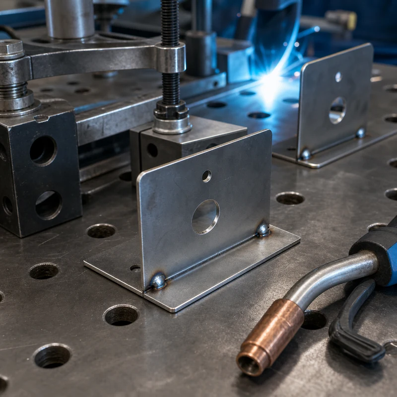
Tack welding is the temporary or semi-permanent weld used to hold parts in position before the final weld is completed. It may look small, but it controls alignment, gap, distortion, and assembly repeatability during sheet metal and welded structure production.

For CNC machined and fabricated assemblies, tack welding is not just a shop-floor shortcut. It is part of process planning. Poor tack weld placement can pull brackets out of position, create stress, or make final welding harder. Good tack welding keeps the part stable while leaving enough access for final welding, grinding, inspection, and finishing.

Quick Comparison of Tack Welding Methods

Tack Weld Type Best Use Main Risk
Small intermittent tacks Thin sheet metal and light brackets Can break if handling is rough
Bridge tacks Maintaining a root gap before final welding Must be removed or fused correctly
Strong temporary tacks Heavy fixtures and structural parts May add distortion if oversized
Corner tacks Boxes, frames, and folded assemblies Can lock in misalignment if sequence is wrong

Why Tack Welding Is Used

Tack welds keep individual pieces from moving while a welder checks fit-up and prepares the final weld sequence. They reduce the need for complex clamps, shorten setup time, and help maintain the intended geometry of brackets, frames, covers, panels, and welded fixtures.

  • Holds parts before final welding
  • Maintains spacing and joint alignment
  • Reduces assembly movement during handling
  • Helps control distortion when used with the right sequence

Where Tack Welding Fits in Fabrication

Tack welding is common in sheet metal enclosures, welded frames, automotive brackets, machinery guards, equipment bases, and prototype metal assemblies. It is especially useful when parts are cut, bent, machined, then welded into a final assembly.

Common Mistakes

The most common problems are oversized tacks, poor cleaning, wrong sequence, bad fit-up, and putting tack welds where final weld access is blocked. A tack weld should support the process, not create a defect that must be repaired later.

Design and Sourcing Notes

Designers should think about tack welding while defining joint access, bend sequence, hole locations, and finishing requirements.

  • Leave enough weld access around corners and flanges.
  • Avoid placing cosmetic surfaces where tack marks will be difficult to remove.
  • Specify critical dimensions after welding if distortion matters.
  • Plan surface treatment after welding and cleanup.

Quality Checks That Matter

Inspection should check alignment, gap, cracks, incomplete fusion, and distortion before final welding proceeds. For precision assemblies, dimensional inspection after welding may be more important than measuring each flat part before welding.

Related MTSPi Resources

FAQ

Is tack welding permanent?

It can become part of the final weld if properly fused, but many tack welds are temporary positioning welds.

Does tack welding cause distortion?

Yes, if tack welds are too large or placed in a poor sequence. Balanced tack placement helps reduce movement.

Should tack welds be inspected?

Yes. Cracked or poorly placed tack welds can affect the final weld and part alignment.

Request A Quote

We'll Send You Back with Price Immediately!

DEC 1-31

XMAS SPECEIL

Up to

40% off

Tack Welding Explained: Purpose, Types, Advantages, and Design Notes

We'll Send You Back with Price Immediately!