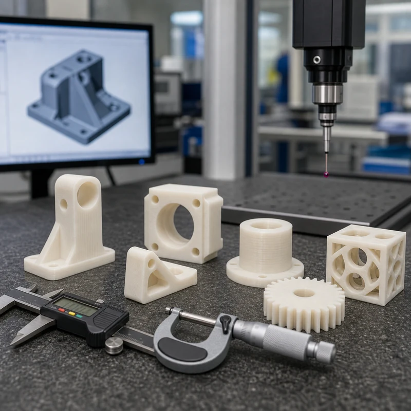
3D printed parts can be accurate enough for prototypes, fixtures, and some end-use applications, but accuracy depends on process, material, geometry, orientation, wall thickness, shrinkage, and post-processing.
The most important question is not whether 3D printing is accurate in general, but whether a specific process can hold the dimensions that matter for the part’s function.
Quick Guide to 3D Printed Parts Dimensional Accuracy
Item
Purpose
Manufacturing Note
FDM
Concept models, fixtures, large prototypes
Layer lines and anisotropy affect accuracy
SLA
Detailed visual prototypes
Good detail but resin behavior matters
SLS/MJF
Functional nylon parts
Good for complex shapes and batches
Metal printing
Complex metal parts
Often needs machining for critical surfaces
Process Selection Notes
The best process depends on material, geometry, tolerance, quantity, surface finish, heat effects, burr requirements, and whether the part needs secondary machining or finishing.
Match the process to the material and geometry.
Confirm critical dimensions before quoting.
Plan finishing and inspection before production.
Use prototypes to validate fit when the assembly risk is high.
Common Applications
3D Printed Parts Dimensional Accuracy is relevant for prototypes, custom components, fixtures, low-volume manufacturing, maintenance parts, and engineering projects where function, cost, and lead time must be balanced.
Cost Factors
Cost usually depends on setup time, material price, number of operations, tool access, tolerance requirements, surface finish, inspection depth, and batch quantity.
Design and Sourcing Notes
The safest design approach is to define the part’s function first, then assign tolerances only where they affect assembly, movement, sealing, safety, or long-term performance.
Avoid unnecessary tight tolerances on non-critical surfaces.
Call out cosmetic surfaces separately from functional surfaces.
Include material, finish, quantity, and inspection notes in the RFQ package.
Quality Checks That Matter
Quality control may include visual inspection, dimensional measurement, thread checks, gauge checks, flatness checks, runout checks, surface finish checks, or CMM inspection depending on the part’s risk and function.
What is the main consideration for 3D printed parts dimensional accuracy?
The main consideration is whether the design, material, and process can meet the functional requirements without adding unnecessary cost or risk.
Can MTSPi help with custom parts for this topic?
Yes. MTSPi can review drawings, material requirements, tolerances, finishing, and inspection needs for custom CNC machined or related manufacturing parts.
What should I send for a quote?
Send 3D CAD, 2D drawings, material grade, quantity, surface finish requirements, tolerance notes, and any critical assembly information.
Quick answer: CNC machining tolerances define how much a finished dimension may vary from the drawing value. Standard tolerances are easier and cheaper to produce, while tight tolerances require better process control, stable material, rigid workholding, suitable tooling, slower machining, and more inspection. The best drawings apply tight tolerances only to features that affect fit, function, sealing, motion, or assembly.
What Are CNC Machining Tolerances?
A tolerance is the acceptable variation around a nominal dimension. If a drawing says 20.00 ±0.05 mm, the feature can pass inspection between 19.95 mm and 20.05 mm. No machining process makes every dimension exactly perfect, so tolerances tell the manufacturer what variation is acceptable.
CNC machining can be very accurate, but not every feature needs the same accuracy. A clearance pocket, cosmetic chamfer, threaded mounting hole, bearing bore, and dowel pin hole all serve different functions. Tolerances should match those functions.
Tight tolerances increase cost because they reduce the room for normal process variation. The machinist may need more careful setup, additional finishing passes, better fixtures, slower cutting, sharper tools, more stable material, in-process checks, and final inspection. If the part moves after material removal or finishing, the process may need stress relief or a different sequence.
Cost often rises fastest when every dimension is marked tight even though only a few features are functional. A good tolerance strategy protects important interfaces while allowing normal manufacturing variation elsewhere.
Factors That Affect CNC Tolerance Capability
Material: Aluminum is generally easier to hold than flexible plastics or difficult heat-resistant alloys.
Geometry: Thin walls, deep pockets, long shafts, and slender features can move during machining.
Setup count: More setups can introduce alignment variation between features.
Tooling: Tool wear, deflection, diameter, coating, and runout affect accuracy.
Workholding: Weak clamping or distorted parts can ruin tolerance even with a good machine.
Heat: Cutting heat and thermal expansion can change measurements.
Finishing: Anodizing, plating, coating, blasting, and polishing may change surfaces or dimensions.
Inspection method: A tolerance is only useful if it can be measured reliably.
ISO 2768 and General Drawing Tolerances
Many mechanical drawings use a general tolerance standard such as ISO 2768 for dimensions that do not have individual tolerances. ISO 2768 tolerance classes help avoid writing a tolerance next to every dimension. However, buyers should still mark critical dimensions separately when the default class is not enough.
For international sourcing, do not assume every shop uses the same default tolerance. Put the standard on the drawing, confirm the class, and identify functional features. If a part will be inspected against GD&T, define datums clearly.
Typical CNC Tolerance Decisions
Feature
Common concern
Practical recommendation
Clearance hole
Bolt or screw must pass through
Use practical clearance unless position is critical
Dowel pin hole
Accurate location and fit
Use reaming, positional tolerance, and gauge/CMM inspection
Bearing bore
Diameter, roundness, finish
Define fit, surface finish, and inspection method
Cosmetic surface
Appearance rather than fit
Use finish notes instead of unnecessary dimensional tolerance
Threaded hole
Fastener engagement and fit
Define thread callout, depth, class, and gauge requirement
Thin wall
Deflection and movement
Avoid tight tolerance unless the wall is supported and measurable
Tolerance and Material Selection
Different materials respond differently to machining. Aluminum is stable and cost-effective for many precision parts. Stainless steel is strong but can work-harden and generate heat. Brass machines cleanly. Titanium and nickel alloys need more careful cutting strategies. Plastics can absorb moisture, flex under clamping, and move after machining. Before locking tolerances, compare options in the CNC materials guide.
Tolerance and Surface Finishing
Finishing can change dimensions and surface texture. Anodizing adds or converts surface layers on aluminum. Plating adds thickness. Powder coating is much thicker than most machined tolerance bands. Polishing can remove material. If a feature is tolerance-critical, state whether the tolerance applies before or after finishing and whether masking is required. See surface treatment options when appearance or corrosion resistance matters.
Inspection Methods for Toleranced Parts
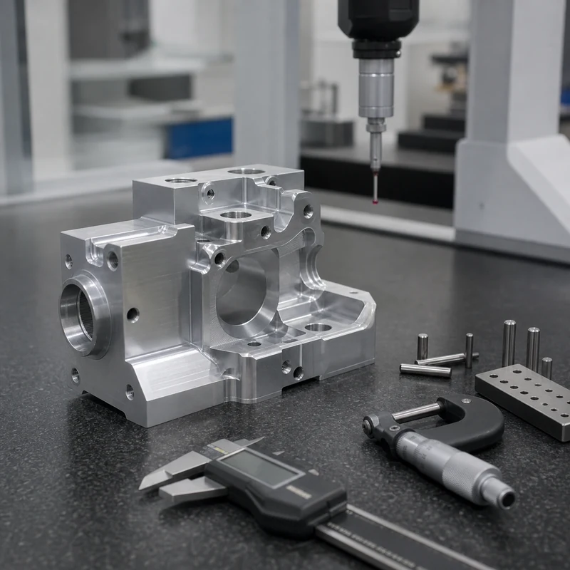
Simple dimensions may be checked with calipers or micrometers. Precision holes may need pin gauges, plug gauges, bore gauges, or air gauges. GD&T features may require CMM inspection. Threads usually need go/no-go gauges. Surface roughness needs a roughness tester. The drawing should not only say what tolerance is required; it should also make the measurement method practical.
How to Write Better Tolerance Notes
Use general tolerances for non-critical dimensions.
Mark critical features separately.
Use GD&T when location, orientation, flatness, or profile matters more than simple size.
Identify datum surfaces clearly.
Do not use tight tolerances to compensate for unclear design intent.
Discuss tolerance after finishing when coating or plating is required.
Ask your supplier which tolerance level is standard and which requires extra cost.
FAQ
What is a normal CNC machining tolerance?
Normal tolerance depends on material, geometry, machine, and supplier standard. Many non-critical machined features can use general tolerances, while precision interfaces require custom callouts.
Can CNC machining hold very tight tolerances?
Yes, but tight tolerance depends on part geometry, material, setup, tooling, inspection, and cost. Not every feature can or should be made extremely tight.
Does anodizing affect tolerance?
Yes. Anodizing can affect dimensions and surface condition. Critical surfaces may need masking or post-finish inspection.
Are plastic tolerances different from metal tolerances?
Often yes. Plastics can move with temperature, moisture, stress, and clamping force, so tolerance planning should be more conservative.
How do I reduce tolerance-related cost?
Use tight tolerances only where function requires them, choose stable materials, avoid thin flexible geometry, and define inspection requirements clearly.
Need tolerance review before quoting?
Send your drawing and mark the critical features. MTSPi can review tolerance, material, machining route, finish, and inspection method before production.
CNC machining tolerances are a design and manufacturing decision, not just numbers on a drawing. Good tolerance planning protects fit and function while avoiding unnecessary machining and inspection cost.