

Categories
Blog Guides Quality & Tolerances

Engineering Drawing Symbols for CNC Machining Quotes

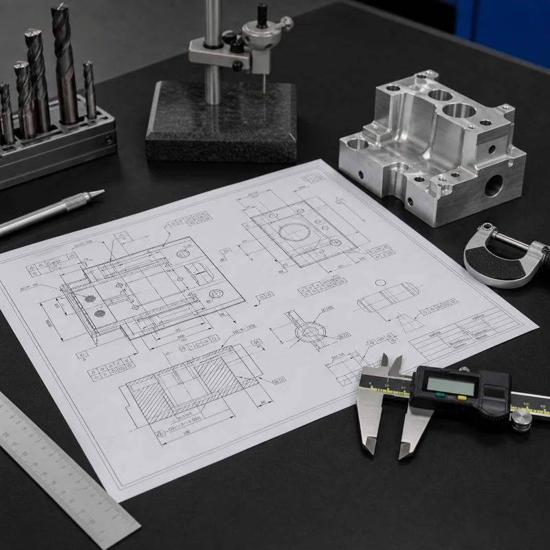
An engineering drawing is more than a picture of a part. For CNC machining, it defines dimensions, tolerances, materials, finishes, threads, inspection requirements, and notes that control how the part should be quoted and produced.

When symbols or abbreviations are missed, the result can be an inaccurate quote, the wrong toolpath, unnecessary rework, or a part that passes size checks but fails assembly. MTSPi reviews CNC machining drawings together with CAD files so unclear requirements are caught before production.

Why Drawing Symbols Matter

A small callout can change the whole manufacturing plan. A simple hole may need drilling only, while a counterbored and tapped hole may need several tools. A general tolerance may be easy to hold, while a tight position tolerance may require a more controlled setup and CMM inspection.

Drawing information What it affects Why it matters in quoting
Dimension Feature size and tool selection Defines the basic material removal plan.
Tolerance Process choice and inspection time Tight limits can add setup and measurement cost.
Surface finish Tooling, feed, finishing, or polishing Finish requirements can change cycle time.
Hole note Drilling, boring, tapping, counterboring Compound hole features need more operations.
GD&T Datum setup and measurement method Controls relationship between features, not just size.

Common Dimension and Feature Abbreviations

Abbreviation or symbol Meaning CNC machining note
DIA Diameter Used for holes, shafts, bosses, and circular features.
R Radius Affects cutter size, corner cleanup, and stress concentration.
TOL Tolerance Defines acceptable variation from nominal size.
REF Reference Information only unless the drawing states otherwise.
THK Thickness Important for plate, sheet, wall, and step features.
DP or DEPTH Depth Controls blind holes, pockets, slots, and threaded features.

Hole and Thread Callouts

Hole notes deserve careful review because they often combine several instructions in one short line. Diameter, depth, thread size, thread depth, countersink angle, counterbore diameter, and through-hole condition can all appear together.

Callout Meaning Manufacturing impact
THRU The hole passes through the part Tool must break through the full thickness.
TAP Internal thread required Needs tapping, thread milling, or forming depending on material.
CBORE Counterbore recess Adds a flat-bottom recess for a fastener head.
CSK Countersink Adds an angled recess and angle control.
M6 x 1 Metric thread size and pitch Requires matching thread tool and inspection gauge.

Fastener features also affect assembly and cost. If a part has many tapped holes, deep threads, or difficult counterbores, review them early with reduce CNC machining cost and the intended assembly method.

Surface Finish and Inspection Notes

Surface finish symbols and roughness values control how smooth a surface must be. A cosmetic face, sealing face, sliding surface, and hidden clearance pocket should not automatically receive the same finish requirement.

Requirement What to clarify Inspection method
Ra value Which surfaces need the value Roughness tester or agreed visual standard
No burrs Edges affected and acceptable break size Visual check, magnification, or edge standard
Critical dimension Sampling plan and report format Caliper, micrometer, pin gauge, CMM, or fixture
Flatness or parallelism Datum and measurement area CMM, surface plate, height gauge, or fixture

For parts with tight tolerances, ask how the supplier will measure the feature before machining starts. MTSPi connects the drawing to CNC machining quality inspection so the inspection plan matches the acceptance requirement.

GD&T Symbols in CNC Projects

Geometric Dimensioning and Tolerancing controls the shape, orientation, and location of features relative to datums. It is especially important when parts must assemble with other components or when hole patterns, flat surfaces, and mating features need controlled relationships.

GD&T concept Plain-English meaning CNC planning issue
Datum Reference feature used for measurement Fixture and inspection setup must match the drawing intent.
Position Allowed location error of a feature Hole patterns may need controlled setup and CMM reporting.
Flatness How much a surface may vary from flat Thin parts may need stress and clamping control.
Parallelism How closely one feature aligns with another Setup sequence and datum handling matter.
Runout Circular variation during rotation Turning process and chucking method are important.

File Package Checklist for an RFQ

  • 3D CAD file for geometry, preferably STEP or another neutral format.
  • PDF drawing with tolerances, material, finish, threads, and notes.
  • Quantity, target lead time, and whether prototypes or production batches are needed.
  • Critical features that affect assembly, sealing, motion, or appearance.
  • Inspection report, material certificate, or finish documentation requirements.

Clear drawing data helps the supplier choose between CNC milling service, CNC turning service, finishing, and inspection options without guessing.

Conclusion

Engineering drawing symbols and abbreviations turn design intent into manufacturing instructions. For CNC machining, the most important items are dimensions, tolerances, hole notes, surface finish, GD&T, material, and inspection requirements. A careful drawing review before quoting saves time, reduces ambiguity, and gives both buyer and supplier a clearer path to acceptable parts.
Categories
Blog Quality & Tolerances

Engineering Tolerances Explained: Meaning, Types, Fits, and Design Use

Engineering tolerance defines how much a manufactured dimension is allowed to vary from the nominal design value. No machining process creates a perfect mathematical part, so tolerances tell the manufacturer what variation is acceptable and what must be rejected.

For CNC parts, good tolerancing is not about making every dimension extremely tight. It is about controlling the features that affect fit, motion, sealing, strength, or alignment while keeping non-critical dimensions practical. This balance improves quality and keeps machining cost under control.

Basic Tolerance Terms

Term Meaning
Nominal dimension The target size shown on the drawing
Upper limit The largest acceptable size
Lower limit The smallest acceptable size
Tolerance zone The total allowed variation between limits
Fit How two mating parts interact after manufacturing
Datum A reference feature used for measurement or assembly

Types of Engineering Tolerances

Dimensional tolerances control size, such as length, width, diameter, or depth. Geometric tolerances, often shown through GD&T, control shape, orientation, position, and runout. General tolerances apply when individual dimensions are not specifically called out.

  • Bilateral tolerance allows variation in both directions, such as +/-0.05 mm.
  • Unilateral tolerance allows variation in only one direction, such as +0.02/-0.00 mm.
  • Limit dimensions show the upper and lower values directly.
  • GD&T controls relationships such as flatness, parallelism, profile, true position, and runout.

Fits Between Mating Parts

Fit Type How It Behaves Example
Clearance fit There is always space between mating parts Shaft rotating inside a bushing
Transition fit May have slight clearance or slight interference Accurate locating dowels
Interference fit Parts press together with force Pressed bearing or permanent sleeve

Using ISO 2768 and General Tolerances

Many drawings use a general tolerance standard such as ISO 2768 for dimensions that do not require special control. This keeps drawings readable and avoids unnecessary tight callouts. Critical features should still have specific tolerances or GD&T notes when function demands it.

How to Choose Practical Tolerances

  • Start with the function of the feature, not the machine capability.
  • Tighten only dimensions that affect assembly, motion, sealing, or performance.
  • Consider material movement, heat treatment, plating, anodizing, and other finishing steps.
  • Discuss inspection method for tight or complex tolerances before production.
  • Use datum structures that reflect how the part actually assembles.

If coating thickness matters, coordinate tolerance planning with the surface treatment process. If complex GD&T is involved, confirm that the quality team can measure the feature reliably.

Tolerance and Cost

Tighter tolerance usually increases cost because it may require slower machining, special tooling, more stable fixtures, extra inspection, or secondary finishing. A realistic tolerance strategy helps suppliers quote accurately and reduces back-and-forth during manufacturing review.

Related MTSPi Resources

FAQ

Should every dimension have a tight tolerance?

No. Only functional or assembly-critical features should be tightly controlled.

What is GD&T used for?

GD&T controls geometry and relationships between features, such as position, flatness, parallelism, and runout.

Can surface finishing change tolerances?

Yes. Plating, anodizing, coating, and heat treatment can change dimensions or part behavior, so they should be considered early.

Categories
Blog CNC Machining Basics Quality & Tolerances

CNC Machining Tolerances: Complete Guide to Standards, Fits, Cost, Materials, and Inspection

Quick answer: CNC machining tolerances define how much a finished dimension may vary from the drawing value. Standard tolerances are easier and cheaper to produce, while tight tolerances require better process control, stable material, rigid workholding, suitable tooling, slower machining, and more inspection. The best drawings apply tight tolerances only to features that affect fit, function, sealing, motion, or assembly.

What Are CNC Machining Tolerances?

A tolerance is the acceptable variation around a nominal dimension. If a drawing says 20.00 ±0.05 mm, the feature can pass inspection between 19.95 mm and 20.05 mm. No machining process makes every dimension exactly perfect, so tolerances tell the manufacturer what variation is acceptable.

CNC machining can be very accurate, but not every feature needs the same accuracy. A clearance pocket, cosmetic chamfer, threaded mounting hole, bearing bore, and dowel pin hole all serve different functions. Tolerances should match those functions.

Standard vs Tight Tolerances

Tolerance type Typical use Cost impact Inspection impact
General tolerance Non-critical dimensions, covers, brackets, simple plates Lower Basic inspection is usually enough
Moderate tolerance Mating surfaces, hole patterns, controlled slots Medium More careful measurement required
Tight tolerance Bearing bores, dowel holes, sealing faces, precision fits Higher CMM, gauges, or special inspection may be needed
GD&T-controlled tolerance True position, flatness, perpendicularity, profile, concentricity Higher when strict Requires datum-based inspection planning

Why Tight Tolerances Cost More

Tight tolerances increase cost because they reduce the room for normal process variation. The machinist may need more careful setup, additional finishing passes, better fixtures, slower cutting, sharper tools, more stable material, in-process checks, and final inspection. If the part moves after material removal or finishing, the process may need stress relief or a different sequence.

Cost often rises fastest when every dimension is marked tight even though only a few features are functional. A good tolerance strategy protects important interfaces while allowing normal manufacturing variation elsewhere.

Factors That Affect CNC Tolerance Capability

  • Material: Aluminum is generally easier to hold than flexible plastics or difficult heat-resistant alloys.
  • Geometry: Thin walls, deep pockets, long shafts, and slender features can move during machining.
  • Setup count: More setups can introduce alignment variation between features.
  • Tooling: Tool wear, deflection, diameter, coating, and runout affect accuracy.
  • Workholding: Weak clamping or distorted parts can ruin tolerance even with a good machine.
  • Heat: Cutting heat and thermal expansion can change measurements.
  • Finishing: Anodizing, plating, coating, blasting, and polishing may change surfaces or dimensions.
  • Inspection method: A tolerance is only useful if it can be measured reliably.

ISO 2768 and General Drawing Tolerances

Many mechanical drawings use a general tolerance standard such as ISO 2768 for dimensions that do not have individual tolerances. ISO 2768 tolerance classes help avoid writing a tolerance next to every dimension. However, buyers should still mark critical dimensions separately when the default class is not enough.

For international sourcing, do not assume every shop uses the same default tolerance. Put the standard on the drawing, confirm the class, and identify functional features. If a part will be inspected against GD&T, define datums clearly.

Typical CNC Tolerance Decisions

Feature Common concern Practical recommendation
Clearance hole Bolt or screw must pass through Use practical clearance unless position is critical
Dowel pin hole Accurate location and fit Use reaming, positional tolerance, and gauge/CMM inspection
Bearing bore Diameter, roundness, finish Define fit, surface finish, and inspection method
Cosmetic surface Appearance rather than fit Use finish notes instead of unnecessary dimensional tolerance
Threaded hole Fastener engagement and fit Define thread callout, depth, class, and gauge requirement
Thin wall Deflection and movement Avoid tight tolerance unless the wall is supported and measurable

Tolerance and Material Selection

Different materials respond differently to machining. Aluminum is stable and cost-effective for many precision parts. Stainless steel is strong but can work-harden and generate heat. Brass machines cleanly. Titanium and nickel alloys need more careful cutting strategies. Plastics can absorb moisture, flex under clamping, and move after machining. Before locking tolerances, compare options in the CNC materials guide.

Tolerance and Surface Finishing

Finishing can change dimensions and surface texture. Anodizing adds or converts surface layers on aluminum. Plating adds thickness. Powder coating is much thicker than most machined tolerance bands. Polishing can remove material. If a feature is tolerance-critical, state whether the tolerance applies before or after finishing and whether masking is required. See surface treatment options when appearance or corrosion resistance matters.

Inspection Methods for Toleranced Parts

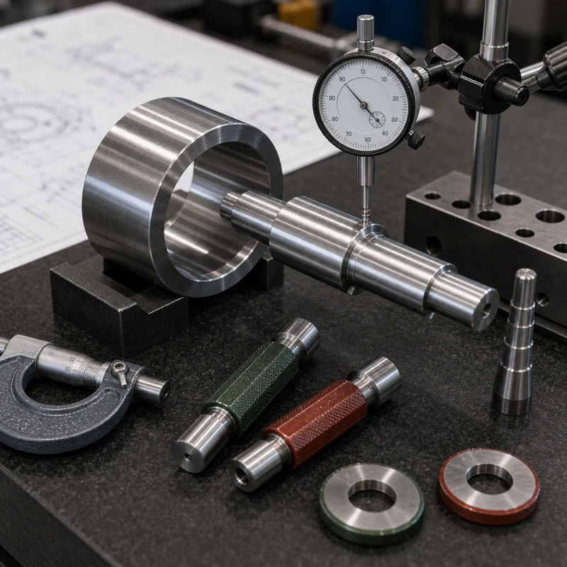
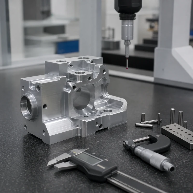
Simple dimensions may be checked with calipers or micrometers. Precision holes may need pin gauges, plug gauges, bore gauges, or air gauges. GD&T features may require CMM inspection. Threads usually need go/no-go gauges. Surface roughness needs a roughness tester. The drawing should not only say what tolerance is required; it should also make the measurement method practical.

How to Write Better Tolerance Notes

  • Use general tolerances for non-critical dimensions.
  • Mark critical features separately.
  • Use GD&T when location, orientation, flatness, or profile matters more than simple size.
  • Identify datum surfaces clearly.
  • Do not use tight tolerances to compensate for unclear design intent.
  • Discuss tolerance after finishing when coating or plating is required.
  • Ask your supplier which tolerance level is standard and which requires extra cost.

FAQ

What is a normal CNC machining tolerance?

Normal tolerance depends on material, geometry, machine, and supplier standard. Many non-critical machined features can use general tolerances, while precision interfaces require custom callouts.

Can CNC machining hold very tight tolerances?

Yes, but tight tolerance depends on part geometry, material, setup, tooling, inspection, and cost. Not every feature can or should be made extremely tight.

Does anodizing affect tolerance?

Yes. Anodizing can affect dimensions and surface condition. Critical surfaces may need masking or post-finish inspection.

Are plastic tolerances different from metal tolerances?

Often yes. Plastics can move with temperature, moisture, stress, and clamping force, so tolerance planning should be more conservative.

How do I reduce tolerance-related cost?

Use tight tolerances only where function requires them, choose stable materials, avoid thin flexible geometry, and define inspection requirements clearly.

Need tolerance review before quoting?

Send your drawing and mark the critical features. MTSPi can review tolerance, material, machining route, finish, and inspection method before production.

Ask MTSPi to review your CNC drawing

Conclusion

CNC machining tolerances are a design and manufacturing decision, not just numbers on a drawing. Good tolerance planning protects fit and function while avoiding unnecessary machining and inspection cost.

Request A Quote

We'll Send You Back with Price Immediately!

DEC 1-31

XMAS SPECEIL

Up to

40% off

CNC Machining Tolerances: Complete Guide to Standards, Fits, Cost, Materials, and Inspection

We'll Send You Back with Price Immediately!