Categories
Blog Industries & Applications Quality & Tolerances

How to Evaluate Precision CNC Machining Companies in Japan

Japan is an important manufacturing market for buyers who need CNC machined parts, precision assemblies, prototypes, and repeat production support. The right supplier can shorten development cycles and reduce sourcing risk, but a country-level search is only a starting point. Engineering teams still need to verify process capability, material control, inspection discipline, communication quality, and delivery reliability.

This MTSPi guide explains how to evaluate CNC machining companies in Japan without relying on a simple brand list. It focuses on practical buying criteria for custom components in aerospace, automotive, medical, robotics, electronics, and industrial equipment. MTSPi can also review drawings through its CNC machining services workflow when a project needs an alternate sourcing path.

Why Buyers Look at Japan for CNC Machining

Japan is known for high-precision manufacturing, disciplined production systems, advanced machine tools, and strong experience in automotive, robotics, electronics, medical equipment, industrial automation, and aerospace-related components. Buyers often look there when accuracy, process stability, and long-term consistency are especially important.

The strongest suppliers tend to combine careful process planning with controlled inspection routines, stable tooling practices, and attention to detail. However, international buyers should still verify capacity, export communication, documentation format, and whether the supplier is comfortable with the required order size.

Supplier Evaluation Checklist

Evaluation Area What to Confirm Why It Matters
Process fit 3-axis milling, 4-axis indexing, 5-axis machining, CNC turning, mill-turn, EDM, grinding, or Swiss-type capability The equipment and setup strategy must match the actual geometry
Material experience Aluminum, stainless steel, tool steel, titanium, brass, copper, and engineering plastics Material behavior affects tolerance, burrs, tool wear, finish, and lead time
Quality planning CMM inspection, calibrated gauges, first-article reports, in-process checks, and revision control Precision parts need measurable evidence, not only visual approval
Production range Prototype, low-volume, bridge production, and repeat-batch support A strong sample must translate into stable repeat orders
Finishing control Anodizing, passivation, plating, bead blasting, polishing, heat treatment, and packaging Post-processing can change dimensions, appearance, and delivery risk
Communication DFM feedback, drawing questions, response time, English documentation, and change tracking Clear technical communication prevents rework

Match the Supplier to the Part Type

A supplier that is excellent for simple brackets may not be the best choice for a thin-wall housing, a tight-concentricity shaft, a cosmetic aluminum enclosure, or a 5-axis aerospace-style component. Build the shortlist around the part, not around the marketing category.

Part Requirement Supplier Capability to Look For Inspection Focus
Complex multi-face geometry 5-axis machining or reliable multi-setup fixture planning Datum relationships, profile tolerance, and repeat setup error
Turned shafts and sleeves CNC turning, mill-turn, or Swiss-type machining Diameter, runout, concentricity, thread quality, and surface finish
Cosmetic enclosures Stable aluminum milling plus finishing coordination Visible surfaces, edge breaks, anodizing allowance, and packaging
Medical or aerospace-style parts Controlled processes, material records, and documented inspection Critical dimensions, traceability, CMM data, and nonconformance handling
Production batches Fixture control, tool-life rules, and repeatable process documentation Lot-to-lot consistency and sampling plan

Quality Questions to Ask Before Placing an Order

  • Which dimensions are highest risk, and how will they be measured?
  • How many setups are planned, and how will datum transfer be controlled?
  • Will inspection be performed before or after surface treatment?
  • Can the supplier provide a sample inspection report for similar tolerances?
  • How are material certificates, drawing revisions, and process changes controlled?
  • What packaging method protects cosmetic surfaces and precision edges during shipment?

Cost, Lead Time, and Hidden Risk

Unit price is only one part of sourcing cost. Buyers should also account for material availability, fixture cost, programming effort, inspection time, finishing lead time, export paperwork, logistics, and the cost of rework if requirements are misunderstood. A quote that ignores tolerance, finish, inspection, or packaging assumptions is not complete.

Japanese sourcing may make sense for very demanding parts, long-term technical programs, or projects where process discipline is more important than the lowest initial cost. For cost-sensitive prototypes or bridge production, buyers may also compare qualified suppliers in other manufacturing regions.

When MTSPi Can Be a Practical Alternative

MTSPi supports custom CNC machining projects that need engineering review, competitive production cost, broad material options, finishing coordination, and inspection documentation. Services include CNC milling, CNC turning, 5-axis CNC machining, prototype machining, and low-volume production. For material selection, review the CNC materials library.

RFQ Package for Accurate Supplier Comparison

RFQ Item Recommended Detail
3D CAD model STEP or equivalent neutral file
2D drawing Tolerances, GD&T, threads, surface finish, datums, and critical notes
Material Grade, temper, standard, and certificate requirement
Finish Process, color, thickness, cosmetic surfaces, and masking notes
Quantity Prototype quantity, annual volume, release schedule, and repeat order expectations
Inspection Critical dimensions, report format, sampling level, and CMM needs

Related MTSPi Resources

FAQ

How should I compare CNC machining companies in Japan?

Compare suppliers by part fit, machine capability, material experience, tolerance control, inspection method, communication, finishing support, and repeat-production reliability.

Should I choose the lowest CNC machining quote?

Not automatically. A low quote can be useful, but it should include the same material, tolerance, finish, inspection, lead-time, and packaging assumptions as the competing quotes.

What files should I send for a CNC machining quote?

Send a 3D CAD file, a 2D drawing, material grade, finish requirements, quantity, target lead time, inspection requirements, and notes on the features that matter most to function.
Categories
Blog CNC Machining Basics Quality & Tolerances

What Is a Micrometer? Precision Measurement for CNC Machined Parts

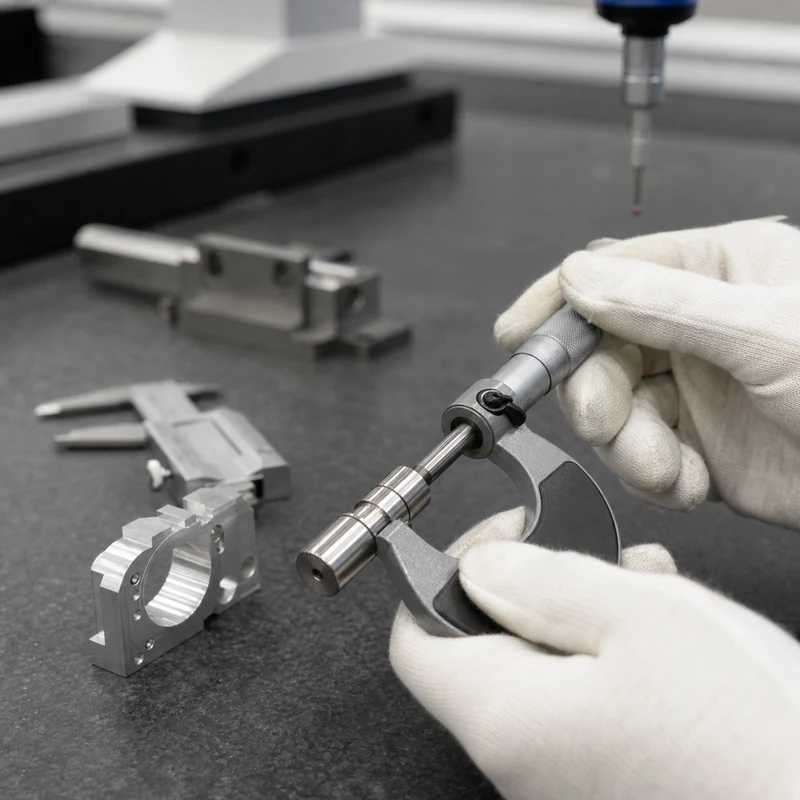
A micrometer is a precision measuring tool used to check small dimensions such as outside diameter, thickness, step height, groove width, and depth. In CNC machining, it is often used for fast, repeatable checks on features that need tighter control than a basic ruler or many general-purpose caliper checks can provide.

Micrometers are important because CNC parts are judged by measurable dimensions, not appearance alone. A shaft may look correct but still fail if its diameter, roundness, or fit tolerance is outside the drawing requirement. MTSPi combines micrometer checks with CNC machining quality inspection, CMM inspection, gauges, and documented quality procedures.

How a Micrometer Works

Most micrometers use a precision screw mechanism. As the thimble turns, the spindle moves toward or away from the anvil by a known distance. The part is placed between the anvil and spindle, and the scale or digital display shows the measured dimension.

Part of the Micrometer Function Inspection Note
Frame Holds the anvil and spindle in alignment A rigid frame helps reduce measurement error
Anvil Fixed measuring face Must be clean and free of burrs
Spindle Moving measuring face Should contact the part with controlled force
Sleeve and thimble Mechanical scale used to read the measurement Requires correct reading technique
Ratchet or friction stop Applies consistent measuring pressure Helps different inspectors get similar results
Lock Holds the spindle position Useful when recording or comparing a reading

Common Types of Micrometers

Micrometer Type Typical Use Example CNC Part Feature
Outside micrometer External diameters and thicknesses Turned shafts, plates, bosses, spacers
Inside micrometer Internal widths and larger bore sizes Housings, slots, internal steps
Depth micrometer Depths of holes, pockets, grooves, and shoulders Milled pockets and blind holes
Blade micrometer Narrow grooves and recessed features Thin slots or retaining-ring grooves
Point micrometer Small grooves or difficult contact areas Fine turned details
Digital micrometer Fast reading and data capture Production inspection and operator checks

Micrometer Accuracy and Resolution

A micrometer is commonly available with fine resolution, but resolution is not the same as total measurement accuracy. Accuracy depends on calibration, operator technique, temperature, tool condition, part cleanliness, and whether the measuring faces contact the intended feature correctly.

  • A clean measuring surface prevents chips or oil from creating a false reading.
  • Consistent ratchet force reduces operator-to-operator variation.
  • Temperature matters because both the part and the tool can expand or contract.
  • Calibration records are needed when measurements support formal quality documentation.

How Micrometers Are Used in CNC Machining

Machinists and inspectors often use micrometers at three stages: incoming material checks, in-process checks, and final inspection. The tool is fast enough for shop-floor use but precise enough to help control critical dimensions.

Incoming Material Checks

Before machining starts, a micrometer can verify bar diameter, plate thickness, stock condition, or pre-machined blanks. This prevents a job from starting with material that cannot clean up to the final dimension.

In-Process Inspection

During machining, micrometers help operators confirm whether tool wear, thermal drift, offsets, or workholding movement are affecting critical features. Early checks reduce scrap because corrections can be made before the entire batch is finished.

Final Inspection

After machining, micrometer measurements may be recorded with other inspection results. For complex geometry, micrometers are usually paired with CMM inspection, bore gauges, thread gauges, height gauges, surface roughness checks, or functional gauges.

Micrometer vs Caliper

Tool Strength Limitation
Micrometer Higher repeatability for specific external, internal, or depth measurements Less versatile; each type covers a narrower measurement range
Caliper Fast general measurements across many feature types Usually less repeatable for very tight tolerances

A caliper is useful for quick checks and general dimensions. A micrometer is preferred when the feature has tighter tolerance, when repeatability matters, or when the contact geometry of the tool better matches the measured feature.

Best Practices for Reliable Micrometer Readings

  • Clean the part and measuring faces before every critical reading.
  • Use the ratchet or friction stop instead of squeezing the part by hand pressure.
  • Measure at multiple positions when checking round parts for taper or out-of-round conditions.
  • Let precision parts stabilize near inspection temperature before final measurement.
  • Store micrometers in a clean case and keep calibration records current.
  • Use the correct micrometer type and range for the feature being inspected.

Where Micrometers Fit in a Quality System

Micrometers are only one part of a complete inspection plan. MTSPi uses them alongside calipers, CMM inspection, thread gauges, pin gauges, visual checks, surface finish checks, and documented process controls. The right inspection method depends on the feature function, tolerance, drawing requirement, and production risk. Learn more on our quality assurance page.

Typical CNC Features Checked With Micrometers

Feature Common Tool What to Watch
Shaft diameter Outside micrometer Check several positions for taper or ovality
Plate thickness Outside micrometer Avoid chips, burrs, and clamping marks
Groove depth Depth or blade micrometer Confirm contact surfaces match the drawing reference
Small step height Depth micrometer Verify datum surface cleanliness
Bore-related features Inside micrometer or bore gauge Confirm the tool is suitable for the bore size and tolerance

How MTSPi Controls Precision Measurements

For custom CNC machining projects, MTSPi reviews the drawing before production to identify critical dimensions, inspection methods, and reporting needs. For tight tolerance parts, we combine stable machining processes with in-process checks and final inspection records. Related services include CNC milling, CNC turning, 5-axis machining, and surface treatment.

Related MTSPi Resources

FAQ

What is a micrometer used for in CNC machining?

A micrometer is used to measure critical dimensions such as shaft diameters, part thicknesses, step heights, grooves, and other features that require repeatable precision checks.

Is a micrometer more accurate than a caliper?

For many tight-tolerance features, yes. A micrometer usually provides better repeatability for a specific measurement, while a caliper is more versatile for general checking.

How often should a micrometer be calibrated?

Calibration frequency depends on usage, required accuracy, quality procedures, and inspection risk. In professional machining environments, micrometers should be checked and calibrated on a defined schedule.

Categories
Blog Quality & Tolerances

What Is CMM Inspection? Complete Guide to Coordinate Measuring Machines for CNC Parts

Quick answer: CMM inspection uses a coordinate measuring machine to measure part features in three-dimensional space. It checks dimensions, hole positions, profiles, flatness, perpendicularity, true position, datums, and GD&T requirements. For CNC machined parts, CMM inspection is most useful when features are tight, complex, datum-based, or critical to assembly.

What Is a CMM?

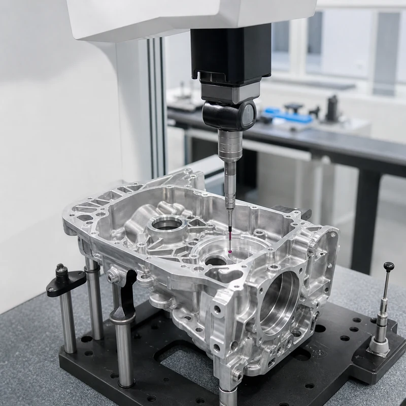
A CMM, or coordinate measuring machine, is an inspection system that measures points on a part using a probe or sensor. The machine records X, Y, and Z coordinates and compares them with the drawing or CAD model. This allows inspectors to verify whether a machined part is within tolerance.

CMM inspection is common for precision CNC parts because many features cannot be judged reliably with calipers alone. Hole patterns, datum relationships, true position, perpendicularity, flatness, and complex profiles need a measurement method that understands the part in 3D space.

What CMM Inspection Can Measure

Feature What CMM checks Why it matters
Hole position Location relative to datums or other holes Controls assembly alignment
Flatness Variation across a surface Important for sealing, mounting, and contact faces
Perpendicularity Angle relationship between axes or surfaces Important for housings, brackets, and fixtures
Profile Deviation from CAD surface or drawing profile Useful for complex milled geometry
True position GD&T-controlled feature location Common for precision hole patterns
Distance and size Lengths, widths, diameters, depths Confirms basic drawing dimensions

How CMM Inspection Works

First, the inspector reviews the drawing and identifies datums, critical features, tolerance zones, and measurement requirements. The part is cleaned and fixtured so it sits in a repeatable position. The CMM then touches or scans selected points. Software compares the measured data with the nominal CAD or drawing values and creates a report.

For repeat production, a CMM program can be saved and reused. This helps measure the same features consistently across batches. For first article inspection, the report may include a broader set of dimensions to validate the initial production process.

CMM Inspection vs Manual Inspection

Inspection method Best for Limitations
Calipers Quick checks of general dimensions Limited for complex geometry and high precision
Micrometers Accurate outside diameters and thickness Feature access and operator method matter
Pin / plug gauges Hole size and fit checks Does not fully describe position or geometry
Thread gauges Internal or external thread fit Does not measure all thread geometry
CMM Datum-based geometry, GD&T, complex parts More time and cost than simple manual checks

When Should Buyers Request CMM Inspection?

  • The part has tight tolerance hole patterns.
  • The drawing uses GD&T such as true position, profile, flatness, or perpendicularity.
  • The part must fit into a larger assembly with little adjustment.
  • The part has multiple machined sides or complex surfaces.
  • The order requires first article inspection or documented quality records.
  • The cost of failure is higher than the cost of measurement.

What Should a CMM Report Include?

A useful CMM report should include part name, drawing number, revision, inspection date, measured features, nominal values, tolerance limits, actual measurements, deviation, pass/fail result, datum reference, and inspector notes. For regulated or high-value projects, material certificate, finish confirmation, and first article documentation may also be needed.

GD&T, Datums, and CMM Inspection

GD&T gives more precise control over how features relate to each other. A hole may pass a simple diameter check but still fail true position if it is not located correctly from the datums. CMM inspection is strong in this situation because it can evaluate the feature within a coordinate system based on the drawing’s datum structure.

If the datum structure is unclear, inspection becomes uncertain. Buyers should make sure the drawing identifies primary, secondary, and tertiary datums where needed. For CNC suppliers, clear datums also help plan workholding and machining sequence.

CMM Inspection for CNC Milling and Turning

For CNC milled parts, CMM inspection is useful for hole patterns, pockets, flatness, profiles, and multi-side relationships. For CNC turned parts, it can support checks for bores, faces, grooves, concentric relationships, cross holes, and secondary milled features. It works best when the drawing clearly separates critical and non-critical dimensions.

How to Reduce Inspection Cost Without Increasing Risk

  • Identify critical dimensions instead of requiring a full report for every feature.
  • Use general tolerance notes for non-critical dimensions.
  • Provide CAD and drawing files together.
  • Define datum structure clearly.
  • Use gauges for simple features and CMM for features that need 3D relationships.
  • Agree on sampling quantity before production.

FAQ

Is CMM inspection required for every CNC part?

No. Many simple parts can be checked with calipers, micrometers, gauges, or visual inspection. CMM is most valuable for precision, complex, or GD&T-controlled parts.

Can CMM inspect threads?

CMM can check thread location and related geometry, but thread fit is usually checked with go/no-go thread gauges.

What is the difference between CMM and FAI?

CMM is a measurement method. First article inspection is a broader process that may include CMM measurements, material checks, finish checks, and documentation.

Does CMM inspection add lead time?

Yes, it can add inspection time, especially for complex reports. But it can reduce risk when parts are expensive or assembly-critical.

What files help CMM inspection?

A 2D drawing with tolerances and datums is essential. A 3D CAD model can help with programming and profile comparison.

Need inspection support for precision parts?

Send your drawing, GD&T notes, CAD file, and critical dimensions. MTSPi can review the right inspection method before quoting.

Contact MTSPi for CNC inspection support

Conclusion

CMM inspection helps confirm that CNC machined parts match the drawing in three-dimensional space. It is most useful for complex geometry, datum-based tolerances, first article inspection, and parts where assembly risk is high.

Categories
Blog CNC Machining Basics Quality & Tolerances

CNC Machining Tolerances: Complete Guide to Standards, Fits, Cost, Materials, and Inspection

Quick answer: CNC machining tolerances define how much a finished dimension may vary from the drawing value. Standard tolerances are easier and cheaper to produce, while tight tolerances require better process control, stable material, rigid workholding, suitable tooling, slower machining, and more inspection. The best drawings apply tight tolerances only to features that affect fit, function, sealing, motion, or assembly.

What Are CNC Machining Tolerances?

A tolerance is the acceptable variation around a nominal dimension. If a drawing says 20.00 ±0.05 mm, the feature can pass inspection between 19.95 mm and 20.05 mm. No machining process makes every dimension exactly perfect, so tolerances tell the manufacturer what variation is acceptable.

CNC machining can be very accurate, but not every feature needs the same accuracy. A clearance pocket, cosmetic chamfer, threaded mounting hole, bearing bore, and dowel pin hole all serve different functions. Tolerances should match those functions.

Standard vs Tight Tolerances

Tolerance type Typical use Cost impact Inspection impact
General tolerance Non-critical dimensions, covers, brackets, simple plates Lower Basic inspection is usually enough
Moderate tolerance Mating surfaces, hole patterns, controlled slots Medium More careful measurement required
Tight tolerance Bearing bores, dowel holes, sealing faces, precision fits Higher CMM, gauges, or special inspection may be needed
GD&T-controlled tolerance True position, flatness, perpendicularity, profile, concentricity Higher when strict Requires datum-based inspection planning

Why Tight Tolerances Cost More

Tight tolerances increase cost because they reduce the room for normal process variation. The machinist may need more careful setup, additional finishing passes, better fixtures, slower cutting, sharper tools, more stable material, in-process checks, and final inspection. If the part moves after material removal or finishing, the process may need stress relief or a different sequence.

Cost often rises fastest when every dimension is marked tight even though only a few features are functional. A good tolerance strategy protects important interfaces while allowing normal manufacturing variation elsewhere.

Factors That Affect CNC Tolerance Capability

  • Material: Aluminum is generally easier to hold than flexible plastics or difficult heat-resistant alloys.
  • Geometry: Thin walls, deep pockets, long shafts, and slender features can move during machining.
  • Setup count: More setups can introduce alignment variation between features.
  • Tooling: Tool wear, deflection, diameter, coating, and runout affect accuracy.
  • Workholding: Weak clamping or distorted parts can ruin tolerance even with a good machine.
  • Heat: Cutting heat and thermal expansion can change measurements.
  • Finishing: Anodizing, plating, coating, blasting, and polishing may change surfaces or dimensions.
  • Inspection method: A tolerance is only useful if it can be measured reliably.

ISO 2768 and General Drawing Tolerances

Many mechanical drawings use a general tolerance standard such as ISO 2768 for dimensions that do not have individual tolerances. ISO 2768 tolerance classes help avoid writing a tolerance next to every dimension. However, buyers should still mark critical dimensions separately when the default class is not enough.

For international sourcing, do not assume every shop uses the same default tolerance. Put the standard on the drawing, confirm the class, and identify functional features. If a part will be inspected against GD&T, define datums clearly.

Typical CNC Tolerance Decisions

Feature Common concern Practical recommendation
Clearance hole Bolt or screw must pass through Use practical clearance unless position is critical
Dowel pin hole Accurate location and fit Use reaming, positional tolerance, and gauge/CMM inspection
Bearing bore Diameter, roundness, finish Define fit, surface finish, and inspection method
Cosmetic surface Appearance rather than fit Use finish notes instead of unnecessary dimensional tolerance
Threaded hole Fastener engagement and fit Define thread callout, depth, class, and gauge requirement
Thin wall Deflection and movement Avoid tight tolerance unless the wall is supported and measurable

Tolerance and Material Selection

Different materials respond differently to machining. Aluminum is stable and cost-effective for many precision parts. Stainless steel is strong but can work-harden and generate heat. Brass machines cleanly. Titanium and nickel alloys need more careful cutting strategies. Plastics can absorb moisture, flex under clamping, and move after machining. Before locking tolerances, compare options in the CNC materials guide.

Tolerance and Surface Finishing

Finishing can change dimensions and surface texture. Anodizing adds or converts surface layers on aluminum. Plating adds thickness. Powder coating is much thicker than most machined tolerance bands. Polishing can remove material. If a feature is tolerance-critical, state whether the tolerance applies before or after finishing and whether masking is required. See surface treatment options when appearance or corrosion resistance matters.

Inspection Methods for Toleranced Parts

Simple dimensions may be checked with calipers or micrometers. Precision holes may need pin gauges, plug gauges, bore gauges, or air gauges. GD&T features may require CMM inspection. Threads usually need go/no-go gauges. Surface roughness needs a roughness tester. The drawing should not only say what tolerance is required; it should also make the measurement method practical.

How to Write Better Tolerance Notes

  • Use general tolerances for non-critical dimensions.
  • Mark critical features separately.
  • Use GD&T when location, orientation, flatness, or profile matters more than simple size.
  • Identify datum surfaces clearly.
  • Do not use tight tolerances to compensate for unclear design intent.
  • Discuss tolerance after finishing when coating or plating is required.
  • Ask your supplier which tolerance level is standard and which requires extra cost.

FAQ

What is a normal CNC machining tolerance?

Normal tolerance depends on material, geometry, machine, and supplier standard. Many non-critical machined features can use general tolerances, while precision interfaces require custom callouts.

Can CNC machining hold very tight tolerances?

Yes, but tight tolerance depends on part geometry, material, setup, tooling, inspection, and cost. Not every feature can or should be made extremely tight.

Does anodizing affect tolerance?

Yes. Anodizing can affect dimensions and surface condition. Critical surfaces may need masking or post-finish inspection.

Are plastic tolerances different from metal tolerances?

Often yes. Plastics can move with temperature, moisture, stress, and clamping force, so tolerance planning should be more conservative.

How do I reduce tolerance-related cost?

Use tight tolerances only where function requires them, choose stable materials, avoid thin flexible geometry, and define inspection requirements clearly.

Need tolerance review before quoting?

Send your drawing and mark the critical features. MTSPi can review tolerance, material, machining route, finish, and inspection method before production.

Ask MTSPi to review your CNC drawing

Conclusion

CNC machining tolerances are a design and manufacturing decision, not just numbers on a drawing. Good tolerance planning protects fit and function while avoiding unnecessary machining and inspection cost.

Request A Quote

We'll Send You Back with Price Immediately!

DEC 1-31

XMAS SPECEIL

Up to

40% off

CNC Machining Tolerances: Complete Guide to Standards, Fits, Cost, Materials, and Inspection

We'll Send You Back with Price Immediately!