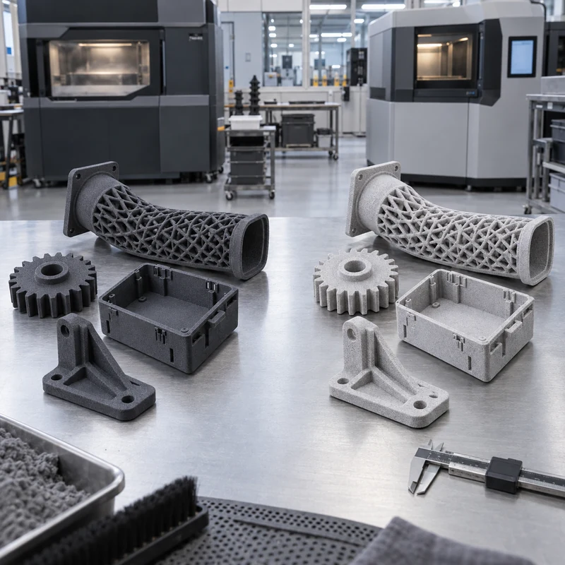
MJF and SLS both build nylon parts inside a powder bed without conventional support structures. That makes both processes useful for complex ducts, housings, clips, brackets, living hinges, lattice features, and low-volume assemblies. The practical differences appear in heat delivery, surface character, dimensional behavior, color, nesting strategy, and supplier workflow.
This MJF vs SLS guide explains those differences for engineers who need functional parts, not just visual models.
Quick Answer
Choose MJF when you want consistent mechanical behavior, fine detail, relatively uniform surfaces, and efficient batches of PA12 parts, especially when dark gray or dyed black is acceptable. Choose SLS when you need broad material availability, flexible build sizes, proven nylon options, or a supplier ecosystem suited to varied quantities and geometries. Test the actual material and orientation when fatigue, snap fits, pressure, or heat matters.
How MJF and SLS Work
SLS scans a laser across each powder layer and sinters the selected cross-section. MJF deposits fusing and detailing agents across the layer, then applies thermal energy. In both methods, surrounding powder supports the part, allowing nested builds and complex shapes without the support marks associated with many resin or filament processes.
MJF vs SLS Comparison
| Factor | MJF | SLS |
|---|---|---|
| Energy delivery | Fusing agents plus thermal energy | Laser scans each cross-section |
| Typical appearance | Graphite gray, often dyed black | Natural white or light gray, easily dyed |
| Surface | Fine, relatively uniform powder texture | Slightly grainier texture depending on machine |
| Materials | Strong focus on PA12 and selected polymers | Broad nylon and specialty-powder ecosystem |
| Mechanical consistency | Often relatively uniform in common PA12 builds | Good but orientation and machine still matter |
| Supports | Not normally required | Not normally required |
| Best fit | Functional batches and detailed PA12 parts | Flexible materials, sizes, and established applications |
Material Options
PA12 is the most common comparison material because it balances toughness, stiffness, chemical resistance, and dimensional stability. PA11 offers greater ductility for impact and snap features. Glass-filled nylons increase stiffness but can become less forgiving and more abrasive. TPU-like powders support flexible components, though machine availability and tolerances differ.
Always compare datasheets for the exact machine-material combination. A generic label such as “nylon” is not enough for a load-bearing design.
Accuracy and Dimensional Control
Both processes are suitable for functional prototypes, but neither should be treated like precision CNC machining. Large flat surfaces can warp, thin walls can move, and holes may print undersize. Geometry, orientation, cooling, packing density, and refresh ratio affect results.
- Add clearance to mating printed parts instead of using nominal CAD fits.
- Avoid very large unsupported flat panels; use ribs or gentle curvature.
- Use consistent wall thickness and gradual transitions.
- Machine or ream critical bores after printing when required.
- Validate snap fits using the intended material, finish, and orientation.
Surface Finish, Color, and Sealing
Both processes leave a matte powder texture. Bead blasting creates a more uniform appearance. Dyeing is common, especially black. Tumbling or chemical smoothing can improve feel and cleanability but may soften small edges or change dimensions. Unsealed nylon remains somewhat porous, so pressure, fluid, and hygiene applications may need infiltration, coating, or a different process.
Strength and Functional Testing
Printed PA12 can support clips, ducts, covers, fixtures, and many load-bearing prototypes. However, long-term creep, fatigue, temperature, moisture, and chemicals should be considered. Use application loads rather than a single tensile value. Test thin hinges, snap arms, screw bosses, and press fits because these features concentrate strain.
Cost and Lead-Time Drivers
| Driver | Why it matters |
|---|---|
| Bounding box | Controls how efficiently parts nest in the build |
| Build height | Adds layers and machine time |
| Part quantity | Dense nesting can lower unit cost |
| Powder refresh | Material handling affects operating cost |
| Cooling | Parts may remain in the build for controlled cooling |
| Finishing | Blasting, dyeing, smoothing, and sealing add steps |
| Inspection | Critical dimensions and lot records add labor |
Design Recommendations
- Use ribs and radii to support thin functional structures.
- Keep escape openings large enough to remove powder from channels.
- Do not create trapped cavities unless powder retention is acceptable.
- Use threaded inserts for repeated assembly rather than relying on printed threads.
- Separate cosmetic and critical dimensional surfaces on the drawing.
- Mark surfaces that will be machined and provide stock where needed.
When CNC Machining Is the Better Choice
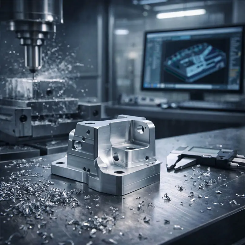
CNC machining is often better when the part needs a specific engineering plastic grade, tight hole or datum tolerances, low surface roughness, transparent material, stable flatness, or traceable stock properties. Printed nylon is excellent for geometry and low-volume function; machined nylon, POM, PEEK, aluminum, or other production materials may be better for final validation.
A Practical Selection Checklist
- What exact polymer grade is required?
- Which dimensions control assembly?
- Will the part see fatigue, heat, moisture, pressure, or chemicals?
- Does color or surface feel matter?
- Can all trapped powder be removed?
- Is the quantity high enough to benefit from dense nesting?
- Should critical features be CNC finished?
Frequently Asked Questions
Is MJF stronger than SLS?
There is no universal answer. With comparable PA12, MJF often provides consistent properties, but machine settings, orientation, geometry, and finishing matter. Use supplier data and functional testing for critical parts.
Which process gives a smoother surface?
MJF often appears finer and more uniform, while SLS can feel slightly grainier. Both remain matte and benefit from blasting, dyeing, or smoothing when appearance matters.
Can MJF or SLS parts be CNC machined?
Yes. Printed parts can be drilled, tapped, reamed, milled, or fitted with inserts, provided the fixture supports the part and the design includes enough material around the feature.
Related MTSPi CNC Resources
- Review our custom manufacturing capabilities for prototype and low-volume programs.
- Explore precision CNC milling for critical datums, bores, sealing faces, and post-processing.
- Compare materials in the MTSPi machining materials library.
- See how we control dimensions through inspection and quality assurance.
- Use our rapid prototyping service to validate geometry before production.