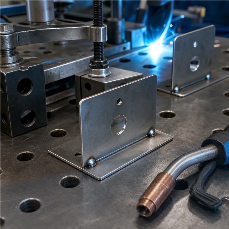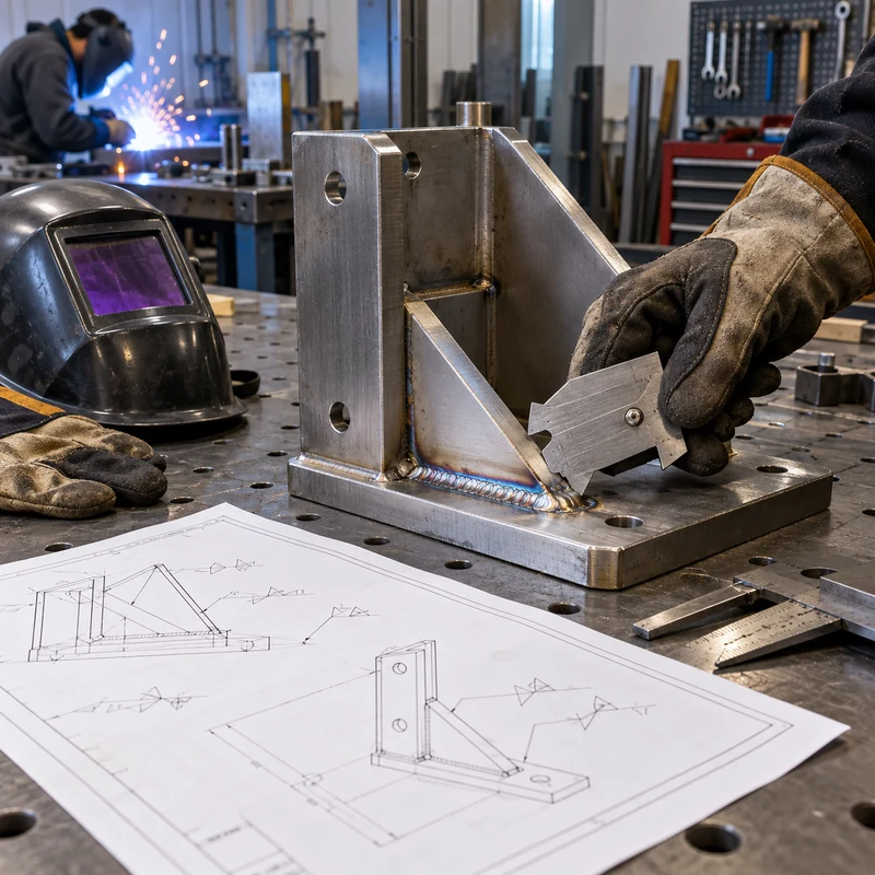
Welding symbols turn an assembly requirement into a compact manufacturing instruction. A few lines and numbers can define the joint, weld type, side, size, length, spacing, contour, finish, and whether the operation happens in the shop or in the field. That compression is useful, but it also means one missed mark can change cost, distortion, accessibility, and inspection.
This guide explains the notation from the viewpoint of designers and buyers of machined assemblies. It focuses on how weld callouts interact with CNC datums, post-weld machining, sealing surfaces, and quotation risk.
Quick Answer: How Do You Read a Welding Symbol?
Follow the same sequence every time: trace the arrow to the joint, identify the governing standard, check which side of the reference line contains the basic symbol, read size information on the left, read length and pitch on the right, then inspect the arrow-reference junction and contour marks for supplementary requirements.
Anatomy of a Welding Symbol
The arrow points to the physical joint. The horizontal reference line carries the weld information. An optional tail can identify the welding process, procedure, specification, or drawing note. A circle at the arrow junction generally indicates an all-around weld, while a flag indicates a field weld.
On drawings that follow AWS conventions, a symbol below the reference line applies to the arrow side and a symbol above applies to the other side. Symbols on both sides call for welding on both faces. ISO drawings can use different reference-line logic, so the title block or general notes must state the standard.
Common Weld Types and Their Uses
| Weld type | Typical symbol form | Common application | Machining implication |
|---|---|---|---|
| Fillet | Triangle | T-joints, lap joints, brackets | Heat can pull machined faces out of position |
| Square groove | Parallel edges | Thin butt joints | Edge squareness and root gap affect penetration |
| V or bevel groove | Angled groove | Thicker structural joints | Preparation may be milled before welding |
| U or J groove | Curved preparation | Heavy sections with controlled filler volume | Usually needs dedicated edge preparation |
| Plug or slot | Hole or slot notation | Joining overlapping plates | Hole location and fit influence load transfer |
| Spot or seam | Resistance-weld notation | Sheet-metal enclosures | Access and electrode clearance must be designed |
How Fillet Weld Dimensions Work
The dimension to the left of a fillet symbol normally controls weld size. Information to the right controls weld length and, for intermittent welds, pitch. A continuous weld may have no length value. When welds appear on both sides, the symbols indicate whether the pattern is aligned or staggered.
Oversizing a fillet does not automatically improve an assembly. It adds heat, filler, time, and distortion. Specify the size required by the load and code, then decide whether intermittent welding can reduce heat without compromising fatigue, sealing, corrosion, or stiffness.
Groove Welds, Root Opening, and Penetration
Groove callouts describe both the weld and the edge preparation. The drawing may identify preparation depth, root opening, groove angle, backing, and complete or partial joint penetration. These details strongly affect labor because deeper preparation requires more cutting, filler, passes, cleaning, and inspection.
For a welded component that will be finish machined, leave enough material around the joint and critical surfaces. The machining allowance must cover predictable distortion without making the section unnecessarily heavy.
Contour and Finish Symbols
Flush, convex, and concave contour marks define the required weld profile. A letter may define the finishing method, such as grinding or machining. A flush requirement should be tied to function: bearing clearance, sealing, cosmetic appearance, or interference avoidance. Applying it everywhere can add substantial cost without improving performance.
AWS and ISO Welding Symbols
| Topic | AWS-style drawing | ISO-style drawing |
|---|---|---|
| Reference line | Usually one line | May use a solid and dashed line |
| Side indication | Above or below the line | Depends on the selected ISO system |
| Fillet size | Commonly leg size | May identify throat or leg with a prefix |
| Units | Often inches on US drawings | Commonly millimetres |
| Best practice | State AWS edition | State ISO edition and system |
Designing Machined Parts for Welding
- Separate locating datums from heat-affected areas whenever possible.
- Add tabs, slots, shoulders, or pilot features to make fixture positioning repeatable.
- Provide torch access and space for clamps, backing, and inspection tools.
- Machine sealing faces, precision bores, and bearing seats after welding when distortion cannot be tolerated.
- Define whether dimensions apply before or after welding and finishing.
- Use a realistic datum scheme for post-weld inspection rather than relying on free-state dimensions alone.
Weld Inspection Checklist
Inspection should match the consequence of failure. Visual checks can verify location, continuity, contour, undercut, porosity, and obvious cracking. Dimensional inspection checks distortion and feature position. Dye penetrant, magnetic particle, ultrasonic, or radiographic methods may be required for critical joints, but the drawing should identify the acceptance standard instead of leaving the shop to guess.
Common Drawing Errors
- Mixing AWS and ISO conventions on one drawing.
- Calling out a full-length weld when intermittent welding was intended.
- Omitting the governing standard, units, or weld procedure reference.
- Placing a weld where a tool, torch, or inspection probe cannot reach.
- Requiring a ground-flush contour without identifying which surface controls function.
- Dimensioning precision holes before welding with no allowance for post-weld correction.
Frequently Asked Questions
What does a circle at the arrow junction mean?
It normally calls for welding around the complete perimeter of the indicated joint. Confirm the governing standard and ensure every segment is physically accessible.
What is the difference between arrow side and other side?
The arrow side is the face indicated by the arrow. The other side is the opposite face. The symbol position maps the requirement to one or both faces according to the drawing standard.
Should precision features be machined before or after welding?
Rough machining can occur before welding, but tight bores, flat sealing faces, and positional features are often finished afterward so the machining operation removes weld-induced distortion.
Related MTSPi CNC Resources
- Review our custom manufacturing capabilities for prototype and low-volume programs.
- Explore precision CNC milling for critical datums, bores, sealing faces, and post-processing.
- Compare materials in the MTSPi machining materials library.
- See how we control dimensions through inspection and quality assurance.
- Use our rapid prototyping service to validate geometry before production.