Categories
Blog Design, Cost & Sourcing

Aluminum Extrusion Design: A DFM Checklist Before Die Release

A manufacturable aluminum extrusion design balances section geometry, alloy, tolerance, and downstream operations before the die is released. The goal is not merely to push a profile through a die. It is to produce stock that can be cut, held, machined, finished, inspected, and assembled without repeated correction.

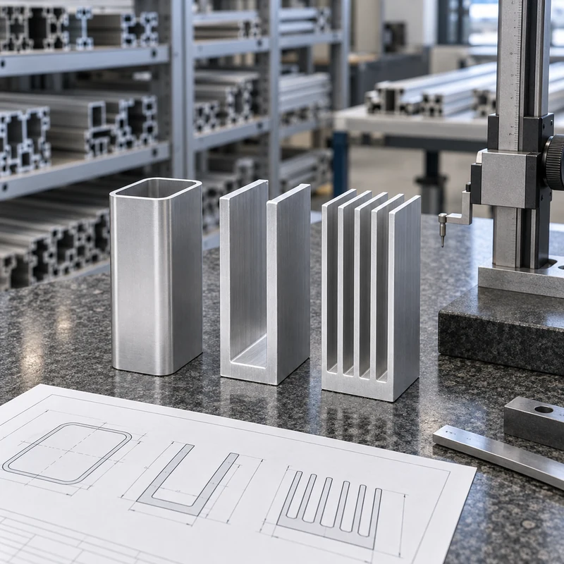
If the cross-section type is still undecided, begin with the comparison of extrusion profile shapes. This guide focuses on the next decision: whether a specific custom section is ready for tooling.

Start With the Assembly Interface, Not a Minimum Wall Number

Identify the surfaces that locate the component, carry load, seal against another part, or remain visible. Mark the assembly datums on the drawing. An external envelope may tolerate more variation than a sliding channel or a machined bearing seat, so applying one tight tolerance to the whole section is usually an unhelpful starting point.

There is no universal minimum wall thickness that is suitable for every alloy, press, profile width, or hollow feature. Ask the extruder to review the actual section. Document the intended alloy and temper, supplied length, annual demand, cut length, finishing route, and any restrictions on profile changes.

Review the Section for Balanced Flow and Robust Tooling

The Aluminum Extruders Council recommends balanced wall thickness and provides design guidance on section geometry. In practice, review abrupt transitions between thick and thin regions, sharp corners, and slender unsupported die features. Smooth transitions and sensible radii can improve feasibility, but the final dimensions must be agreed with the toolmaker.

Design feature Question for review Possible direction
Thick base with very thin fins Can the section be produced consistently? Rebalance section geometry with thermal and structural analysis
Deep narrow channel Does the opening require a fragile die feature? Widen access or reconsider the channel arrangement
Abrupt section change Can the transition be softened? Introduce a compatible radius or gradual change
Critical close-fitting slot Is extrusion tolerance sufficient after finishing? Reserve a controlled machining operation if necessary
Thin clamping wall Will machining restraint distort it? Provide supported locating and clamping surfaces

Each change has a functional tradeoff. A thicker fin may improve manufacturability while changing heat transfer or mass. Do not approve a die-driven geometry change without checking the original design requirement.

Separate As-Extruded and Machined Requirements

Extrusion standards address more than width and height. Straightness, twist, wall thickness, and other geometric characteristics can matter across a supplied length. The AEC tolerance resources direct designers to relevant industry standards; the drawing and purchase agreement should identify the applicable requirements rather than simply asking for “precision extrusion.”

Create two explicit states when appropriate: the purchased profile and the finished component. A bolt pattern machined after cutting should be controlled from finished-part datums. A long as-extruded surface may need a different inspection setup than the local interface machined into it.

For example, a housing rail might use its bottom face as the finished assembly datum. If the blank is held from an uncontrolled side wall, the hole pattern may be repeatable in the fixture but misplaced relative to the mating base. That is a datum-planning problem, not a reason to tighten every extrusion dimension.

Design the Machining Setup Before Approving the Die

Check tool access, available clamping area, cut-off allowance, burr removal, and access for inspection. A profile that looks efficient in cross-section may require multiple setups to drill inaccessible features. A small geometry change can sometimes simplify the entire route.

  • Identify which surfaces will locate the blank during each operation.
  • Confirm whether thin walls need support under clamping loads.
  • Specify machining allowance where cleanup is required.
  • Review access for cutters, drills, taps, and deburring tools.
  • Define which dimensions are accepted before and after finishing.

Submit the profile model and finished-part drawing together when discussing secondary milling and drilling. The unmachined stock definition alone is not enough to quote the finished part reliably.

Include Finish and Cosmetic Requirements in the Review

Anodizing, coatings, and mechanical finishing affect the acceptance plan. Mark visible faces and agree the reference sample, permitted marks, masking requirements, and inspection condition. Where fit is sensitive, evaluate the selected finish’s dimensional effect with the finishing supplier instead of assuming a universal coating allowance.

Keep engineering finish requirements separate from aesthetic descriptions. “Silver finish” does not specify an anodizing process, thickness requirement, sealing requirement, or color tolerance. The surface-treatment overview can help structure the finishing discussion.

A Practical Die-Release Gate

Before authorizing tooling, ask the responsible parties to sign off the same drawing revision. Record open issues with an owner and disposition rather than relying on comments spread across email attachments.

  1. Function: critical interfaces and loads are identified.
  2. Feasibility: the extruder has reviewed the complete section, alloy, and tolerances.
  3. Operations: cutting, machining, finishing, and inspection routes are defined.
  4. Acceptance: first-article scope, sample requirements, and change approval are agreed.
  5. Commercial scope: die ownership, maintenance, minimum order, and revision costs are clarified.

This review does not eliminate trials. It makes the trial meaningful by defining what must be demonstrated and which deviations require approval.

Frequently Asked Questions

Should all profile walls be identical?

Balanced walls are a useful design objective, not an absolute rule. Functional needs may require differences that the extruder must evaluate.

Can extrusion replace every machining operation?

No. Features that vary along the length, cross holes, precision seats, or local pockets commonly require secondary operations.

Can I specify machining tolerances on the full extrusion?

Discuss each functional requirement with the supplier. A finished tolerance may require machining rather than being economical or feasible directly from extrusion.

What files should accompany an RFQ?

Provide the section drawing, 3D model, finished-part drawing, alloy and temper, finish, volumes, and inspection requirements.

Technical reference basis: Aluminum Extruders Council design tips, design considerations, and tolerance resources. Workflow examples are illustrative and require supplier-specific feasibility review.
Categories
Blog CNC Materials

Aluminum Symbol: Al Meaning, Common Confusions, and Alloy Codes

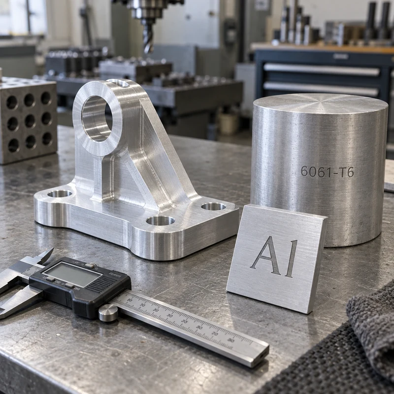
The chemical symbol for aluminum is Al: an uppercase A followed by a lowercase l. Its atomic number is 13. Aluminum and aluminium are names for the same element and use the same symbol. In chemistry, Al identifies the element; in manufacturing, an alloy and temper such as 6061-T6 provide additional information needed to specify a material.

Aluminum Symbol and Element Facts

Item Meaning
Chemical symbol Al
How to read it Capital A, lowercase letter l; not capital I
Element names Aluminum / aluminium
Atomic number 13, the number of protons
Relative atomic mass Approximately 26.98
Periodic table position Group 13, Period 3
Common oxidation state +3

The atomic number and atomic mass answer different questions. The number 13 identifies the element through its proton count. The value around 26.98 describes relative atomic mass; it is not an alloy number, a strength rating, or a density. For broader material properties, see how aluminum behaves as a metal.

Al, AL, AI, Al3+, and Al2O3: What Is the Difference?

Small typographic differences can change the meaning of a label. The second character in Al is the lowercase letter found at the start of the word light. A font with clear letter shapes helps distinguish it from an uppercase I.

Notation What it represents How to interpret it
Al The chemical element aluminum Correct capitalization for the element symbol
AL May be an abbreviation or label in a document Not the standard chemical symbol; read the document legend
AI Capital A followed by capital I Not the symbol for aluminum
Al3+ An aluminum ion carrying a +3 charge The superscript describes charge, not three aluminum atoms
Al2O3 Aluminum oxide A compound containing aluminum and oxygen in a 2:3 atomic ratio
6061-T6 An aluminum alloy and temper designation A material condition, not a chemical formula

In a formula, a subscript indicates the relative count of atoms. A superscript charge indicates an ion’s electrical charge. Neither notation identifies a machining grade. Aluminum oxide is also chemically different from metallic aluminum, so its properties should not be substituted for those of an aluminum workpiece.

Does Aluminium Have a Different Symbol?

No. The spelling aluminum is common in American English, while aluminium is common in British English and many other regions. Both use Al. An international drawing should nevertheless identify the governing material standard, because common element names do not establish equivalence between regional alloy specifications.

How to Read an Aluminum Material Callout

Consider the illustrative note Aluminum alloy 6061-T6. It contains three levels of information:

  1. Aluminum alloy identifies the material family.
  2. 6061 identifies an alloy designation. In the wrought aluminum system, the 6xxx family is associated with magnesium and silicon as major alloying additions.
  3. T6 identifies a temper: solution heat-treated and artificially aged.

The four digits are not a percentage formula. Do not read 6061 as a statement of aluminum purity. Similarly, T6 does not mean six percent of another element, a six-hour treatment, or a universal strength value. Mechanical properties must be checked for the specified product form, thickness, and applicable specification.

A different temper can change the engineering behavior of the same alloy. T651 adds a defined stress-relief condition to the heat-treatment description. Substituting one condition for another should be reviewed against the drawing rather than accepted because both names begin with 6061.

Why “Material: Al” Is Not Enough for a CNC Quote

Imagine two suppliers receive a bracket drawing with only the note “Al.” One quotes a readily available general-purpose alloy, while the other assumes a higher-strength grade. The quotes now describe different materials. Even if the dimensions match, the strength, cost, finishing response, and documentation may differ.

A clearer RFQ identifies the alloy, temper, stock form where relevant, applicable material specification, and certificate requirements. Keep finish and dimensional requirements explicit too. A compact review checklist is:

  • Which alloy and temper are required?
  • Which product specification applies to the purchased stock?
  • Are substitutions permitted, and who approves them?
  • Which dimensions must be checked after finishing?
  • Is material certification or lot traceability required?

Use the engineering materials overview to explore material choices, and supply those decisions with the model and drawing when requesting machining of a precision bracket or housing. A chemical symbol alone cannot define acceptance criteria.

Keep Pure-Aluminum Data Separate From Alloy Data

Reference tables often give pure aluminum a density of approximately 2.70 g/cm3 near room temperature and a melting point near 660°C. These are useful element facts. An engineering alloy can have a different density and a melting interval rather than the same single melting point.

Likewise, there is no single strength or hardness that applies to every part labeled aluminum. Alloy composition, temper, processing, temperature, and product form matter. For a weight estimate, use an appropriate density for the specified grade. For a load calculation, use the applicable design data and material condition rather than an element-summary table.

A Practical Label-Reading Example

Suppose a supplier labels a billet “6061-T6” while the inspection sheet lists Al among the detected elements. The billet label identifies the claimed alloy and condition; the element result identifies chemistry. These records answer different questions. An elemental reading alone does not establish temper, and a handwritten stock label does not replace the required certificate.

For receiving inspection, compare the purchase order, drawing revision, material certificate, and stock identification. Resolve discrepancies before machining. This is where understanding the difference between an element symbol and an alloy designation becomes useful beyond a chemistry definition.

Frequently Asked Questions

Is the aluminum symbol Al or AI?

It is Al, with a lowercase l. AI, using an uppercase I as the second character, is not the chemical symbol for aluminum.

Does Al always mean pure aluminum?

Al is the element symbol. On a product label or engineering document it may indicate the aluminum material family, so check the alloy, temper, and specification before assuming purity.

Is aluminum oxide the same material as aluminum metal?

No. Al identifies aluminum, while Al2O3 is aluminum oxide, a compound with different properties. Its subscript numbers describe composition, not an alloy grade.

Can I order a machined part by specifying Al only?

That leaves the material definition incomplete. Provide an alloy and temper or describe the requirements and request a material recommendation for approval before production.

Technical basis: PubChem aluminum element data, the Aluminum Association alloy-designation overview, and published aluminum temper definitions. Worked procurement examples are illustrative.

Categories
Blog Design, Cost & Sourcing Quality & Tolerances

Welding Symbols Explained: Meaning, Types, and Drawing Notes for Machined Assemblies

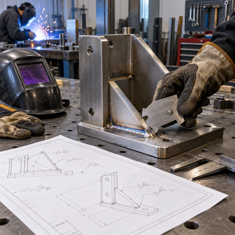
Welding symbols turn an assembly requirement into a compact manufacturing instruction. A few lines and numbers can define the joint, weld type, side, size, length, spacing, contour, finish, and whether the operation happens in the shop or in the field. That compression is useful, but it also means one missed mark can change cost, distortion, accessibility, and inspection.

This guide explains the notation from the viewpoint of designers and buyers of machined assemblies. It focuses on how weld callouts interact with CNC datums, post-weld machining, sealing surfaces, and quotation risk.

Quick Answer: How Do You Read a Welding Symbol?

Follow the same sequence every time: trace the arrow to the joint, identify the governing standard, check which side of the reference line contains the basic symbol, read size information on the left, read length and pitch on the right, then inspect the arrow-reference junction and contour marks for supplementary requirements.

Anatomy of a Welding Symbol

The arrow points to the physical joint. The horizontal reference line carries the weld information. An optional tail can identify the welding process, procedure, specification, or drawing note. A circle at the arrow junction generally indicates an all-around weld, while a flag indicates a field weld.

On drawings that follow AWS conventions, a symbol below the reference line applies to the arrow side and a symbol above applies to the other side. Symbols on both sides call for welding on both faces. ISO drawings can use different reference-line logic, so the title block or general notes must state the standard.

Common Weld Types and Their Uses

Weld type Typical symbol form Common application Machining implication
Fillet Triangle T-joints, lap joints, brackets Heat can pull machined faces out of position
Square groove Parallel edges Thin butt joints Edge squareness and root gap affect penetration
V or bevel groove Angled groove Thicker structural joints Preparation may be milled before welding
U or J groove Curved preparation Heavy sections with controlled filler volume Usually needs dedicated edge preparation
Plug or slot Hole or slot notation Joining overlapping plates Hole location and fit influence load transfer
Spot or seam Resistance-weld notation Sheet-metal enclosures Access and electrode clearance must be designed

How Fillet Weld Dimensions Work

The dimension to the left of a fillet symbol normally controls weld size. Information to the right controls weld length and, for intermittent welds, pitch. A continuous weld may have no length value. When welds appear on both sides, the symbols indicate whether the pattern is aligned or staggered.

Oversizing a fillet does not automatically improve an assembly. It adds heat, filler, time, and distortion. Specify the size required by the load and code, then decide whether intermittent welding can reduce heat without compromising fatigue, sealing, corrosion, or stiffness.

Groove Welds, Root Opening, and Penetration

Groove callouts describe both the weld and the edge preparation. The drawing may identify preparation depth, root opening, groove angle, backing, and complete or partial joint penetration. These details strongly affect labor because deeper preparation requires more cutting, filler, passes, cleaning, and inspection.

For a welded component that will be finish machined, leave enough material around the joint and critical surfaces. The machining allowance must cover predictable distortion without making the section unnecessarily heavy.

Contour and Finish Symbols

Flush, convex, and concave contour marks define the required weld profile. A letter may define the finishing method, such as grinding or machining. A flush requirement should be tied to function: bearing clearance, sealing, cosmetic appearance, or interference avoidance. Applying it everywhere can add substantial cost without improving performance.

AWS and ISO Welding Symbols

Topic AWS-style drawing ISO-style drawing
Reference line Usually one line May use a solid and dashed line
Side indication Above or below the line Depends on the selected ISO system
Fillet size Commonly leg size May identify throat or leg with a prefix
Units Often inches on US drawings Commonly millimetres
Best practice State AWS edition State ISO edition and system

Designing Machined Parts for Welding

  • Separate locating datums from heat-affected areas whenever possible.
  • Add tabs, slots, shoulders, or pilot features to make fixture positioning repeatable.
  • Provide torch access and space for clamps, backing, and inspection tools.
  • Machine sealing faces, precision bores, and bearing seats after welding when distortion cannot be tolerated.
  • Define whether dimensions apply before or after welding and finishing.
  • Use a realistic datum scheme for post-weld inspection rather than relying on free-state dimensions alone.

Weld Inspection Checklist

Inspection should match the consequence of failure. Visual checks can verify location, continuity, contour, undercut, porosity, and obvious cracking. Dimensional inspection checks distortion and feature position. Dye penetrant, magnetic particle, ultrasonic, or radiographic methods may be required for critical joints, but the drawing should identify the acceptance standard instead of leaving the shop to guess.

Common Drawing Errors

  • Mixing AWS and ISO conventions on one drawing.
  • Calling out a full-length weld when intermittent welding was intended.
  • Omitting the governing standard, units, or weld procedure reference.
  • Placing a weld where a tool, torch, or inspection probe cannot reach.
  • Requiring a ground-flush contour without identifying which surface controls function.
  • Dimensioning precision holes before welding with no allowance for post-weld correction.

Frequently Asked Questions

What does a circle at the arrow junction mean?

It normally calls for welding around the complete perimeter of the indicated joint. Confirm the governing standard and ensure every segment is physically accessible.

What is the difference between arrow side and other side?

The arrow side is the face indicated by the arrow. The other side is the opposite face. The symbol position maps the requirement to one or both faces according to the drawing standard.

Should precision features be machined before or after welding?

Rough machining can occur before welding, but tight bores, flat sealing faces, and positional features are often finished afterward so the machining operation removes weld-induced distortion.

Related MTSPi CNC Resources

Categories
Blog Guides Quality & Tolerances

Engineering Drawing Symbols for CNC Machining Quotes

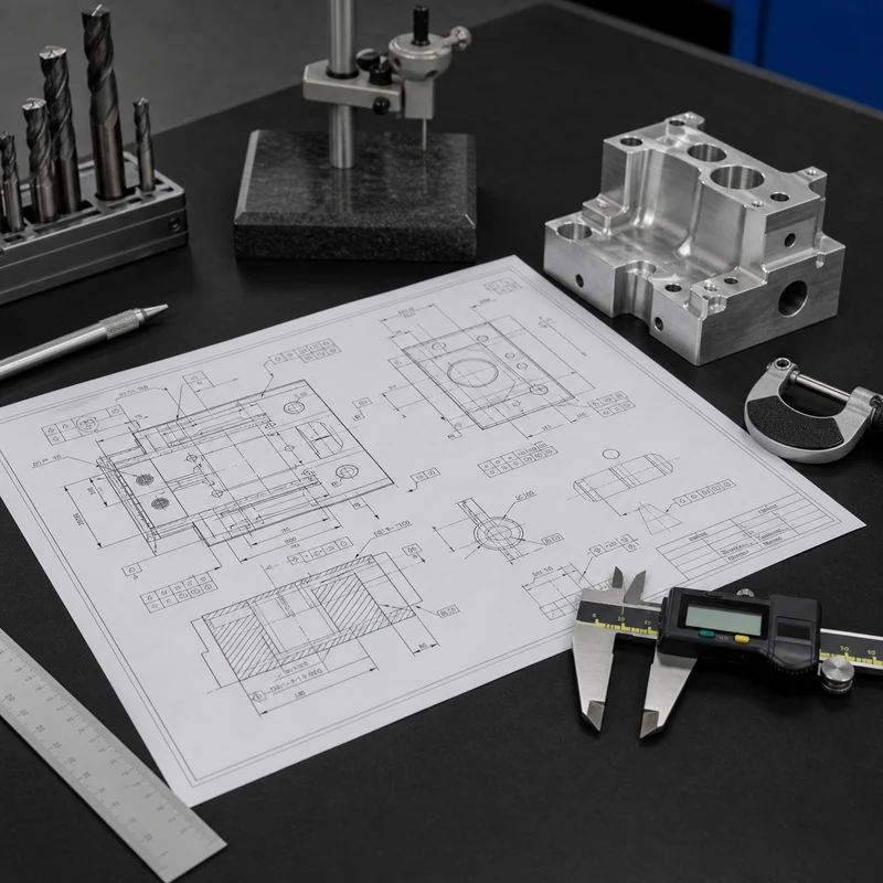
An engineering drawing is more than a picture of a part. For CNC machining, it defines dimensions, tolerances, materials, finishes, threads, inspection requirements, and notes that control how the part should be quoted and produced.

When symbols or abbreviations are missed, the result can be an inaccurate quote, the wrong toolpath, unnecessary rework, or a part that passes size checks but fails assembly. MTSPi reviews CNC machining drawings together with CAD files so unclear requirements are caught before production.

Why Drawing Symbols Matter

A small callout can change the whole manufacturing plan. A simple hole may need drilling only, while a counterbored and tapped hole may need several tools. A general tolerance may be easy to hold, while a tight position tolerance may require a more controlled setup and CMM inspection.

Drawing information What it affects Why it matters in quoting
Dimension Feature size and tool selection Defines the basic material removal plan.
Tolerance Process choice and inspection time Tight limits can add setup and measurement cost.
Surface finish Tooling, feed, finishing, or polishing Finish requirements can change cycle time.
Hole note Drilling, boring, tapping, counterboring Compound hole features need more operations.
GD&T Datum setup and measurement method Controls relationship between features, not just size.

Common Dimension and Feature Abbreviations

Abbreviation or symbol Meaning CNC machining note
DIA Diameter Used for holes, shafts, bosses, and circular features.
R Radius Affects cutter size, corner cleanup, and stress concentration.
TOL Tolerance Defines acceptable variation from nominal size.
REF Reference Information only unless the drawing states otherwise.
THK Thickness Important for plate, sheet, wall, and step features.
DP or DEPTH Depth Controls blind holes, pockets, slots, and threaded features.

Hole and Thread Callouts

Hole notes deserve careful review because they often combine several instructions in one short line. Diameter, depth, thread size, thread depth, countersink angle, counterbore diameter, and through-hole condition can all appear together.

Callout Meaning Manufacturing impact
THRU The hole passes through the part Tool must break through the full thickness.
TAP Internal thread required Needs tapping, thread milling, or forming depending on material.
CBORE Counterbore recess Adds a flat-bottom recess for a fastener head.
CSK Countersink Adds an angled recess and angle control.
M6 x 1 Metric thread size and pitch Requires matching thread tool and inspection gauge.

Fastener features also affect assembly and cost. If a part has many tapped holes, deep threads, or difficult counterbores, review them early with reduce CNC machining cost and the intended assembly method.

Surface Finish and Inspection Notes

Surface finish symbols and roughness values control how smooth a surface must be. A cosmetic face, sealing face, sliding surface, and hidden clearance pocket should not automatically receive the same finish requirement.

Requirement What to clarify Inspection method
Ra value Which surfaces need the value Roughness tester or agreed visual standard
No burrs Edges affected and acceptable break size Visual check, magnification, or edge standard
Critical dimension Sampling plan and report format Caliper, micrometer, pin gauge, CMM, or fixture
Flatness or parallelism Datum and measurement area CMM, surface plate, height gauge, or fixture

For parts with tight tolerances, ask how the supplier will measure the feature before machining starts. MTSPi connects the drawing to CNC machining quality inspection so the inspection plan matches the acceptance requirement.

GD&T Symbols in CNC Projects

Geometric Dimensioning and Tolerancing controls the shape, orientation, and location of features relative to datums. It is especially important when parts must assemble with other components or when hole patterns, flat surfaces, and mating features need controlled relationships.

GD&T concept Plain-English meaning CNC planning issue
Datum Reference feature used for measurement Fixture and inspection setup must match the drawing intent.
Position Allowed location error of a feature Hole patterns may need controlled setup and CMM reporting.
Flatness How much a surface may vary from flat Thin parts may need stress and clamping control.
Parallelism How closely one feature aligns with another Setup sequence and datum handling matter.
Runout Circular variation during rotation Turning process and chucking method are important.

File Package Checklist for an RFQ

  • 3D CAD file for geometry, preferably STEP or another neutral format.
  • PDF drawing with tolerances, material, finish, threads, and notes.
  • Quantity, target lead time, and whether prototypes or production batches are needed.
  • Critical features that affect assembly, sealing, motion, or appearance.
  • Inspection report, material certificate, or finish documentation requirements.

Clear drawing data helps the supplier choose between CNC milling service, CNC turning service, finishing, and inspection options without guessing.

Conclusion

Engineering drawing symbols and abbreviations turn design intent into manufacturing instructions. For CNC machining, the most important items are dimensions, tolerances, hole notes, surface finish, GD&T, material, and inspection requirements. A careful drawing review before quoting saves time, reduces ambiguity, and gives both buyer and supplier a clearer path to acceptable parts.

Request A Quote

We'll Send You Back with Price Immediately!

DEC 1-31

XMAS SPECEIL

Up to

40% off

Engineering Drawing Symbols for CNC Machining Quotes

We'll Send You Back with Price Immediately!