Categories
Blog Manufacturing Process Comparisons

Large Format 3D Printing: Design, Joining, and CNC Finishing

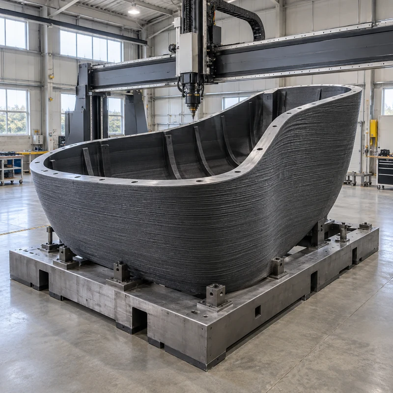
Large format 3D printing produces oversized components using a suitable additive process, sometimes followed by joining and CNC finishing. The useful question is not simply whether a model fits inside a printer. It is whether the complete manufacturing route can deliver the required interfaces, stability, surface condition, and inspection evidence.

This guide focuses on polymer components and tooling. Metal additive manufacturing has different equipment, support, thermal-processing, and qualification requirements. Neither route should be selected from a machine’s advertised build volume alone.

Define the Finished Part Before Choosing a Machine

Separate the overall shape from the functional interfaces. A full-size appearance model may accept visible layer lines. A fixture may need accurate locating pads. A mold may require a qualified working surface and temperature capability. These are different acceptance problems even when the outer dimensions are similar.

List the supplied dimensions, transport envelope, service environment, assembly loads, and surfaces requiring measurement. Identify the part’s inspection condition: unsupported, located on datums, or held in an assembly fixture. A large compliant shell can produce different measurements under different restraints.

Match the Process to the Entire Manufacturing Route

Route Reason to consider it Question before quotation
Large filament extrusion Full-scale polymer prototypes and suitable functional parts Can the selected material and geometry be produced without unacceptable distortion?
Pellet-fed extrusion Large near-net shapes with substantial material deposition What machining and finishing steps are included?
Large resin printing Detailed models or patterns where the chosen resin is suitable How are supports, curing, and dimensional acceptance controlled?
Sectioned assembly Parts exceeding a practical build or handling envelope How will the joints be located, inspected, and qualified?

Manufacturer specifications must be checked for the particular machine and material. There is no single build-size limit or tolerance that applies to an entire process family. Large-printing equipment also differs in its thermal controls and processing workflow.

For context on the broader alternatives, see the requirement-based process comparison. An attractive process name cannot replace a review of the actual part.

One Piece or Several Sections?

A one-piece build avoids assembly joints but can create a long, expensive job with demanding handling and finishing requirements. Dividing the part can improve access and allow smaller sections to be replaced, but adds alignment work and another source of variation. Neither choice is automatically cheaper.

Compare both routes against the same finished specification. Include the time required for adhesive preparation and cure, fastening, surface blending, alignment fixtures, and final inspection. Consider where the completed component will be installed: a part that fits the printer but not the building access route creates a separate logistics problem.

For a hypothetical equipment cover, a split near a removable service panel might be acceptable while a seam across a prominent cosmetic face is not. For a loaded tool, joint placement needs an engineering review of the load and temperature conditions. Appearance alone is not a sound basis for locating that joint.

Design Joints as Functional Features

Provide a defined locating method rather than relying on a long butt joint to align itself. Depending on the application, mating steps, dowels, fixtures, or designed fastening features may help establish position. Agree which features carry load and which only locate the assembly.

  • For bonded joints, validate material compatibility, preparation, bond geometry, and cure conditions.
  • For fastened joints, check local wall support, access, preload effects, and repeated assembly requirements.
  • For thermoplastic welding, confirm material and process compatibility with a qualified supplier.
  • For every joint, define the acceptance method and permissible mismatch.

There is no universal strength ranking between adhesives, fasteners, and welded joints. Geometry, material condition, temperature, and loading direction all matter. Use representative testing where the failure consequences justify it.

Reserve CNC Finishing for the Surfaces That Need It

Thermwood describes a near-net-shape workflow in which a part is printed oversize and then CNC trimmed to its final geometry. This is a useful manufacturing strategy, not a promise that any print can achieve any tolerance through machining.

Identify the mounting pads, sealing faces, locating holes, or other interfaces that require finishing. Define machining allowance with the manufacturing team, allowing for the selected print route and anticipated variation. Avoid removing so much stock that a cutter exposes an unsuitable internal structure or leaves a wall below its functional thickness.

Plan how the blank will be held. Clamping against a flexible printed wall can alter its shape, so the measured result in the fixture may differ from the released part. Datums, supports, cutter access, and tool travel need to be reviewed together. A part fitting the printer does not guarantee it fits the subsequent machining setup.

Discuss the critical interfaces and blank condition when requesting secondary milling of functional surfaces. Confirm material suitability and machine capacity with MTSPi before committing to a production route.

Validate Behavior at the Intended Scale

A small sample can help compare surfaces or basic material behavior, but it does not demonstrate the dimensional stability of a much larger geometry. Long spans, uneven section thickness, handling supports, and the sequence of processing operations deserve specific attention.

Record build orientation and post-processing conditions for the approved sample. Define the environment and support condition for dimensional inspection. Where elevated temperature or sustained loading matters, qualify the finished construction, including any coating, joint, or insert, rather than assuming that a resin name establishes performance.

Request a Delivered-Part Quote

Compare proposals that include the same scope: printing, material conditioning, support removal where applicable, joining, machining, finishing, inspection, packaging, and transport. Ask which requirements are guaranteed, which depend on a trial, and which require a design change.

A low print-only price can be misleading if another proposal includes the fixture and finished interface measurements. For interim production planning, the bridge-production acceptance checklist adds useful controls for revision and lot traceability.

Frequently Asked Questions

Does large format have a fixed size definition?

Not one universal threshold across suppliers. Specify actual part dimensions and the complete production route instead of relying on the label.

Must a large print be machined afterward?

No. Some as-printed parts meet their requirements. Machining is useful when selected interfaces need a condition the printing route cannot reliably provide.

Is printing in one piece always stronger?

No. Performance depends on material, build direction, geometry, and loads. A designed and qualified assembly may be suitable; a poorly positioned joint may not be.

Can a printed mold be used at any temperature?

No. Validate the complete tool against its thermal and mechanical duty. Material choice, construction, working surface, and operating conditions must be compatible.

Technical reference basis: Thermwood LSAM near-net-shape documentation and BigRep large-format equipment and design guidance. Examples are illustrative, not claims about MTSPi equipment ownership or documented customer test results.
Categories
Blog Manufacturing Process Comparisons

3D Printing for Low-Volume Production: A Bridge-to-Molding Plan

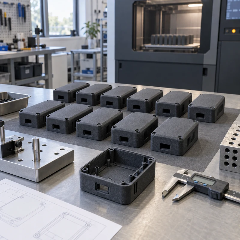
3D printing can supply a low-volume production batch while an injection mold is being developed, provided the printed material, process, and inspection plan are approved for the actual use. A successful bridge-production plan defines what may ship, how each batch will be accepted, and when the program will change to molded parts. It is not simply a larger prototype order.

Decide What the Interim Parts Must Prove

Start with the consequence of failure. A display housing for an internal sales review does not have the same requirements as a customer-delivered enclosure exposed to heat, sunlight, cleaning chemicals, or repeated screw assembly. Write down the operating environment and the release authority before selecting a printer or material.

Intended use Useful acceptance evidence Do not assume
Appearance review Approved color and surface sample Printed texture reproduces molded texture
Assembly trial Mating-part checks and measured interfaces One fit check establishes production capability
Functional pilot Application-specific load and environmental tests A similarly named resin has identical properties
Customer shipment Approved specification, lot records, release inspection A prototype approval covers end-use shipment

Where certification or regulated use applies, confirm which manufacturing changes require additional qualification. A material datasheet alone does not establish compliance of a finished assembly.

Choose the Process Against the Failure Mode

SLA, SLS, MJF, and material-extrusion processes can address different combinations of appearance, geometry, material behavior, and throughput. Compare candidate processes using the same part and inspection criteria rather than a generic claim about the strongest or cheapest technology. The requirement-based printing process comparison provides a starting framework.

Orientation affects printability, support placement, finish, and dimensional results. The printer manufacturer’s validated guidance should inform the build setup. Keep supports away from critical cosmetic or mating surfaces where practical, and include cleaning and post-curing when the selected system requires them. Lock the approved build recipe before interpreting results from multiple deliveries as comparable.

Do not substitute an SLA resin described as ABS-like for molded ABS without checking the properties relevant to the application. Repeated flexing, long-term temperature exposure, creep, and chemical resistance may decide suitability even when both samples initially fit.

Compare Total Accepted-Part Cost

There is no universal quantity at which molding becomes cheaper. Use supplier quotations for the same revision and include tooling, setup, finishing, inspection, expected scrap, and delivery. A simple preliminary model is:

Break-even quantity = (mold tooling and setup cost minus print setup cost) / (accepted printed-part cost minus accepted molded-part cost).

This expression is useful only when the denominator is positive and the compared parts satisfy the same requirements. For an illustrative calculation, a tooling difference of $8,000 and a unit-cost difference of $16 gives 500 accepted parts. Those figures are invented planning inputs, not MTSPi pricing. A design revision that changes the tool, or a finishing operation omitted from one quotation, can invalidate the comparison.

Separate economics from availability. Printing may remain appropriate for a time-critical interim batch even when molding has a lower eventual unit cost. For a broader quotation checklist, review the factors behind printing and scale-up cost.

Make Each Batch Traceable

Printed parts can have effective traceability; it must be specified and maintained. A useful traveler connects the part revision to material lot, machine, build identifier, approved orientation, post-processing records, inspection results, and release date. Decide whether individual serialization or batch identification is needed.

  • Approve a representative sample before the first production release.
  • Identify critical dimensions and how they will be measured.
  • Agree sampling frequency and the response to a failed check.
  • Record build or material changes before shipping affected parts.
  • Retain a reference sample when useful for later comparison.

A hypothetical enclosure program might check mounting-hole location with a fixture, verify lid engagement with a mating part, and inspect the cosmetic face under agreed lighting. These checks answer different questions. Passing the visual inspection does not replace measuring the mounting interface.

Control the Transition to Molded Production

Maintain a revision-controlled comparison between the interim part and the molded design. Draft, ribs, wall thickness, gate locations, ejection marks, and shrinkage behavior require a molding-specific review. A printed prototype that assembles successfully does not prove that the same geometry is ready for tool release.

Close the bridge phase after the production process has passed its agreed qualification and supply can meet the schedule. Keep interim and molded stock identifiable when their material or performance differs. Establish disposition for remaining inventory instead of silently mixing both routes under an uncontrolled label.

When planning the surrounding mechanical parts, share the assembly model, tolerances, and expected production sequence with MTSPi through the project inquiry page. Confirm the proposed scope and process with the team rather than assuming every manufacturing route is available.

Frequently Asked Questions

Can printed bridge parts be sold to customers?

Yes, when the material and finished part are qualified for their intended use and the required approvals and traceability are in place. Prototype acceptance alone is insufficient.

Does bridge production always mean printing?

No. The term describes an interim production role. Machining, casting, or temporary tooling may also be suitable, depending on the part and schedule.

Are printed molds the same as directly printed parts?

No. Direct printing creates the component. A printed mold is tooling used to form a separate component, with its own limits on temperature, pressure, wear, and tool life.

Should every small batch avoid injection molding?

No. Required resin behavior, geometry, repeatability, and available tooling can make molding appropriate even for modest quantities.

Technical reference basis: Formlabs model-orientation guidance and injection-molding application documentation. Cost figures and inspection examples are illustrative planning examples, not production test data.

Categories
Blog Design, Cost & Sourcing Guides

AI 3D Model Generators: How to Evaluate Models Before Printing or CNC

AI 3D model generators can turn text or images into meshes quickly, making them useful for concept exploration, visualization, games, and early prototype forms. A downloadable mesh is not automatically a manufacturing-ready model.

Mechanical production requires consistent scale, watertight geometry, controlled surfaces, feature dimensions, tolerances, materials, assembly logic, and revision history. This guide shows how to evaluate generated output before spending money on printing or machining.

Quick Answer

Use AI-generated models as concept geometry. Repair and validate the mesh before 3D printing. Rebuild critical products in parametric CAD before CNC machining, tooling, or tolerance-controlled production.

Comparison at a Glance

Factor Option A Option B
Output Usually polygon mesh Production engineering prefers controlled CAD
Dimensions May be arbitrary or inconsistent Must be explicitly defined
Topology Can contain holes and self-intersections Needs watertight valid geometry
Revisions Prompt changes may alter everything CAD supports controlled feature changes
Manufacturing Good for concept prints after repair Not automatically CNC-ready

What to Test in a Tool

Compare prompt adherence, image-to-3D quality, symmetry, view consistency, mesh density, export formats, commercial rights, privacy, and the ability to edit selected regions. Free access limits can change, so verify current terms directly.

Mesh Quality Checklist

Inspect for non-manifold edges, inverted normals, intersecting shells, thin walls, floating geometry, excessive polygons, and open surfaces. Confirm scale before slicing.

  • Repair watertightness
  • Reduce unnecessary polygons carefully
  • Check minimum wall and clearance
  • Orient and add supports
  • Run a small test print

From Mesh to CAD

Automatic surface conversion can create heavy, fragile models. For functional products, use the generated mesh as a visual reference and rebuild sketches, planes, holes, datums, ribs, and interfaces as controlled features.

3D Printing Use

Concept meshes can work well for appearance models once repaired. Choose FDM for inexpensive form studies, SLA for smooth detail, and powder-bed nylon for functional geometry.

Why CNC Needs More

CNC needs exact surfaces, machinable features, tool access, corner radii, setups, material, tolerances, and drawings. A visually plausible mesh can contain geometry that cannot be held, reached, or inspected.

  • Create STEP geometry
  • Define datums and tolerances
  • Review tool access
  • Select production material
  • Add drawings for threads and finishes

Licensing and Confidentiality

Confirm whether generated assets may be used commercially and whether uploaded product images or CAD data are retained for model training. Do not upload confidential customer geometry without approved terms.

Frequently Asked Questions

Can an AI mesh be CNC machined directly?

Sometimes CAM can import meshes, but product-quality CNC work generally benefits from repaired surfaces or rebuilt CAD plus controlled drawings.

Are free AI 3D tools truly free?

Many use credits, limited exports, watermarks, non-commercial terms, or paid high-resolution output. Verify current conditions.

What file format is best?

STL or OBJ suits mesh workflows; STEP is preferred for controlled mechanical CAD and CNC quoting.

Related MTSPi Resources

Categories
Blog Design, Cost & Sourcing Manufacturing Process Comparisons

Vacuum Casting vs 3D Printing: Choosing the Right Plastic Prototype Process

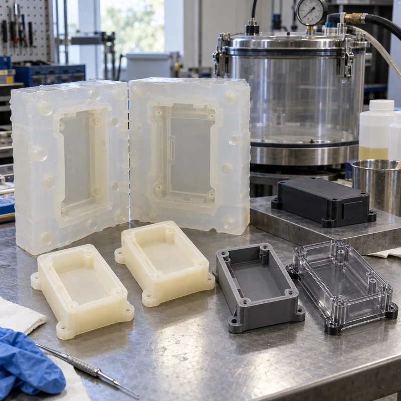
Vacuum casting and 3D printing are both practical routes for plastic prototypes and low-volume parts, but they solve different problems. Printing builds each part directly from digital data. Vacuum casting first needs a master pattern and silicone mold, then reproduces polyurethane parts with molded appearance.

The decision should be based on what the prototype must prove, how many copies are needed, and whether appearance, material behavior, geometry, or speed carries the most value.

Quick Answer

Choose 3D printing for one-off geometry, rapid iteration, complex internal features, and early design learning. Choose vacuum casting when you need a small batch of consistent, molded-looking parts with color, texture, transparency, or overmold simulation.

Comparison at a Glance

Factor Option A Option B
Quantity Excellent for one to several parts Better economics for repeated small batches
Tooling No physical mold Silicone mold and master required
Geometry Strong for complex shapes Needs castable geometry and venting
Surface Process-dependent layer or powder texture Replicates master surface closely
Changes Update file and print again May require new master and mold

How the Processes Work

Additive systems create parts layer by layer using filament, resin, powder, or other feedstock. Vacuum casting places a master inside silicone, removes the master after curing, then draws mixed polyurethane into the mold under vacuum.

Material and Functional Behavior

Printed polymers and cast polyurethane families can imitate different stiffness, clarity, heat resistance, and impact behavior, but neither should automatically be treated as production injection-molded resin. Use CNC machining when production-intent stock properties are essential.

Cost and Lead Time

Printing avoids mold preparation, making it fast for first parts and frequent revisions. Vacuum casting adds master and mold time but spreads that setup over repeated copies. Finishing, inspection, paint, inserts, and assembly may dominate either quote.

  • Define quantity and revision risk
  • Specify visible and critical surfaces
  • Identify inserts, colors, and textures
  • Quote finishing separately

Design Rules

Printing needs process-specific minimum walls, holes, supports, and powder escape. Casting needs draft where practical, controlled wall thickness, gates, vents, and accessible parting strategy.

Scaling Toward Production

Use early prints to validate form, then cast parts for stakeholder trials or pilot builds. Before injection molding, update CAD and drawings using test results rather than assuming prototypes prove production capability.

Quality Checklist

Inspect dimensions that control assembly, visual limits, bubbles, voids, warpage, inserts, color, hardness, and surface finish. Approve a representative sample and define how later parts are compared.

Frequently Asked Questions

Which is cheaper?

3D printing is usually cheaper for one or a few parts; vacuum casting often becomes competitive for repeated small batches with molded appearance.

How many parts can a silicone mold make?

Tool life depends on geometry, resin, undercuts, temperature, and surface requirements. Suppliers should quote an expected range rather than a guaranteed universal number.

Can vacuum-cast parts replace injection-molded testing?

They can support many fit, appearance, and limited functional tests, but material and process differences must be considered.

Related MTSPi Resources

Categories
Blog Guides Manufacturing Process Comparisons

SLA vs FDM 3D Printing: Choosing the Right Prototype Before CNC Machining

SLA vs FDM 3D Printing: Choosing the Right Prototype Before CNC Machining is a practical manufacturing question because the answer affects cost, lead time, material behavior, inspection, and the path from prototype to production. For MTSPi CNC customers, the key is not simply naming a process, but understanding how the process connects with machined parts, fixtures, tolerances, surface requirements, and final assembly.

This guide explains SLA vs FDM from an engineering and purchasing point of view. It is written for product developers, mechanical engineers, sourcing teams, and buyers who need clear decisions rather than generic process descriptions.

Quick Answer

Choose SLA for smooth visual models and fine details. Choose FDM for quick, low-cost functional mockups, larger prototypes, and early fit checks. Move to CNC machining when the prototype must match production material, tolerance, surface finish, or strength.

Key Differences at a Glance

Point Option A Option B
Material Photopolymer resin Thermoplastic filament
Surface finish Smooth and detailed Visible layer lines
Strength Resin-dependent, sometimes brittle Better for basic functional handling
Cost Moderate, depends on resin and finishing Usually low for early prototypes
Best use Appearance, fine detail, small features Fit checks, fixtures, larger simple forms

How the Process Choice Affects Real Parts

A manufacturing method should be selected around the feature that actually controls function. Cosmetic surfaces, hidden support features, threads, bores, sealing faces, heat-transfer areas, and assembly datums do not carry the same risk. When those requirements are mixed together without priority, quotes become inconsistent and production becomes harder to control.

The safest workflow is to define the part requirement first, then match the process. A printed prototype may answer shape questions, a molded sample may answer appearance questions, and a CNC machined sample may answer tolerance, material, and functional questions. Many successful projects use more than one method before the final design is locked.

Design and Manufacturing Considerations

  • Use SLA when small details or smooth surfaces drive the review.
  • Use FDM when speed, size, and basic function matter more than appearance.
  • Do not validate tight production tolerances with low-resolution printed parts.
  • Prototype threaded or snap-fit features carefully because printed behavior differs from machined or molded parts.
  • Move critical functional tests to CNC or production-equivalent processes.

Cost, Lead Time, and Risk Factors

Cost is driven by setup, tooling, material, machine time, inspection, finishing, and revision risk. A low unit price is not always the lowest project cost if it creates rework later. For prototypes and low-volume orders, flexibility can be more valuable than a process with a lower theoretical unit cost.

  • Use standard materials and standard feature sizes when they do not weaken the design.
  • Separate critical tolerances from general dimensions so the supplier knows where to focus.
  • Confirm surface finish and cosmetic requirements before production begins.
  • Avoid late changes to mounting holes, connector openings, datum faces, and threaded features.
  • Send CAD files and 2D drawings together when tolerances, threads, or finishes matter.

Quality Checks Before Production

A good quality plan checks the features that influence assembly and performance. Depending on the part, this may include dimensional inspection, thread gauges, surface roughness, flatness, perpendicularity, burr control, coating thickness, visual appearance, and fit with mating parts.

When This Topic Matters for CNC Buyers

SLA vs FDM matters when a team is comparing prototype routes, validating a design, replacing a weak supplier, or trying to reduce manufacturing cost without damaging function. The best choice is usually the process that answers the current engineering question with the least unnecessary risk.

MTSPi CNC Engineering Notes

MTSPi CNC supports precision CNC milling, turning, rapid prototyping, low-volume production, finishing, and inspection for custom parts. If your project uses molding, casting, welding, PCB assemblies, or 3D printing, CNC machining can still be important for datums, holes, threads, sealing faces, fixtures, and production-ready prototypes.

Frequently Asked Questions

Can this process replace CNC machining?

Sometimes it can replace CNC for non-critical geometry, but CNC is often still needed when tight tolerances, real engineering material, threads, flat sealing faces, or precise mating features are required.

What files help MTSPi CNC review a project?

STEP or STP files are useful for geometry. A 2D drawing is important for tolerances, materials, threads, surface finish, inspection requirements, and notes that are not obvious from the CAD model.

How do I reduce manufacturing risk?

Define critical features, avoid unnecessary tight tolerances, confirm material and finish requirements, and use prototypes to validate assembly before committing to higher-volume tooling or production.

Related MTSPi Resources

Request A Quote

We'll Send You Back with Price Immediately!

DEC 1-31

XMAS SPECEIL

Up to

40% off

SLA vs FDM 3D Printing: Choosing the Right Prototype Before CNC Machining

We'll Send You Back with Price Immediately!