Categories
Blog Quality & Tolerances

Injection Molding Bubbles and Voids: An Evidence-Led Troubleshooting Guide

An apparent bubble in an injection-molded part may be a gas pocket or a shrinkage void. Identify the mechanism before changing the process. Gas-related defects can involve moisture, entrained air, or degradation. A shrinkage void forms when internal contraction is not adequately supplied with material during solidification. The same visual description does not justify the same correction.

Preserve Evidence Before Adjusting Settings

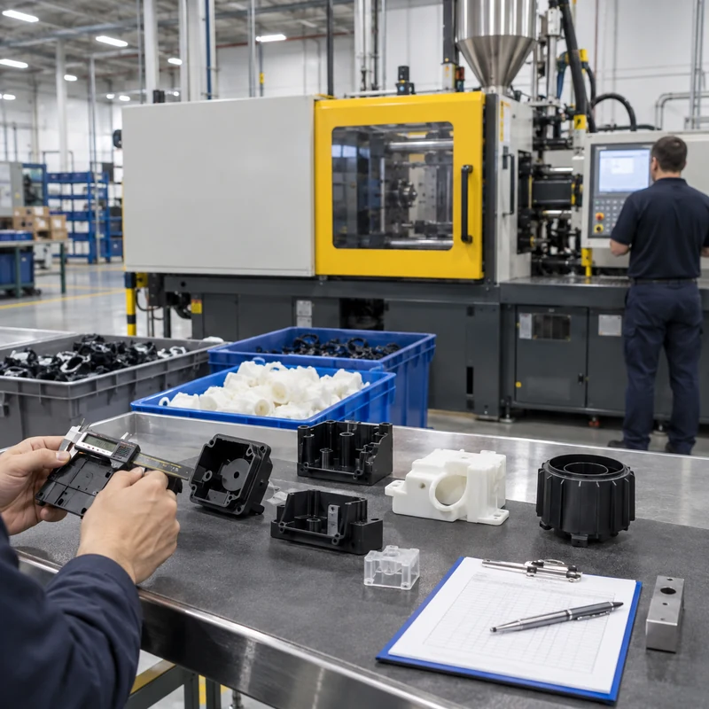
Retain defective and acceptable samples, identify the cavity, and record the material lot, startup condition, and current settings. Photograph the location relative to the gate and thick sections. Note whether the defect is repeatable in one location or scattered across the part.

Transparent parts make internal defects easier to see, but a sound-looking exterior does not rule out an internal void. Where the application warrants it, use an approved inspection method such as controlled sectioning or suitable imaging. Do not heat unknown plastics with an open flame as an informal diagnostic test.

Observation Useful investigation What it does not prove alone
Pocket in the center of a thick section Packing effectiveness and cooling-related shrinkage That moisture can be ruled out without other evidence
Scattered pockets with surface streaking Resin condition, moisture, contamination, and melt history That drying is the only cause
Defect near a flow-ending region Fill pattern and vent condition That a higher injection speed will solve it
Problem after a prolonged machine interruption Residence time and material degradation That every subsequent shot is acceptable

BASF’s troubleshooting guidance distinguishes gas bubbles from voids and notes the connection between voids and thick, internally molten regions. Use such guidance as a diagnostic starting point, not a replacement for examining the actual part.

Check Resin Condition at the Point of Use

For moisture-sensitive grades, verify the material supplier’s drying requirements and the condition of material entering the machine. A dryer temperature display does not confirm the pellets have reached an acceptable moisture level. Review residence time in the dryer, loading practice, and exposure during transfer.

Keep resin grade, colorant, additives, and regrind proportion identifiable. If the defect appeared after a material change, retain samples from both conditions and check whether the change was approved. Drying an unfamiliar mixture more aggressively is not a substitute for establishing what material is being processed.

Review the Melt and Filling History

Inspect the approved processing window against actual operating conditions. Barrel settings, measured melt behavior, recovery conditions, and residence time must be considered together. A machine idle period or an unsuitable shot-to-barrel relationship can change the thermal history even when the temperature setpoints remain unchanged.

Air management also deserves a targeted review. Examine the filling sequence, vent condition, and melt preparation with the process engineer. Raising temperature or changing injection speed without identifying the mechanism may move the defect or introduce another one. The melt-temperature and material guide explains why processing advice must be grade-specific.

Document one controlled adjustment at a time when isolating a cause. Where variables interact, use an agreed experimental plan rather than informal simultaneous changes. Keep machine operation and mold intervention within trained personnel’s procedures.

Test Whether Packing Can Feed the Critical Region

If evidence indicates a shrinkage void, review whether the flow path remains capable of supplying the region during packing. A holding-pressure increase cannot compensate indefinitely for a gate that has already frozen. It can also create flash, residual stress, or dimensional changes elsewhere.

A qualified process study may examine part-weight response to hold time together with gate behavior and defect incidence. Record the stable process conditions and use the material supplier’s limits. Do not treat a single heavier part as proof that the internal defect has disappeared.

Address Geometry When the Process Window Is Too Narrow

Thick regions cool and shrink differently from adjacent thin sections. Protolabs’ moldability guidance identifies thick sections as a risk for sink and void formation. Evaluate whether a heavy boss or local mass can be cored while preserving its structural function. Review wall transitions, gate location, and the ability to feed the affected region with the tooling specialist.

Consider a hypothetical mounting boss attached to a thin housing wall. If the pocket repeatedly appears inside the boss, making the entire surrounding wall thicker may add material and create additional cooling problems. A revised boss and rib arrangement may be worth evaluating instead. That decision requires a new structural and molding review, not just a cosmetic repair.

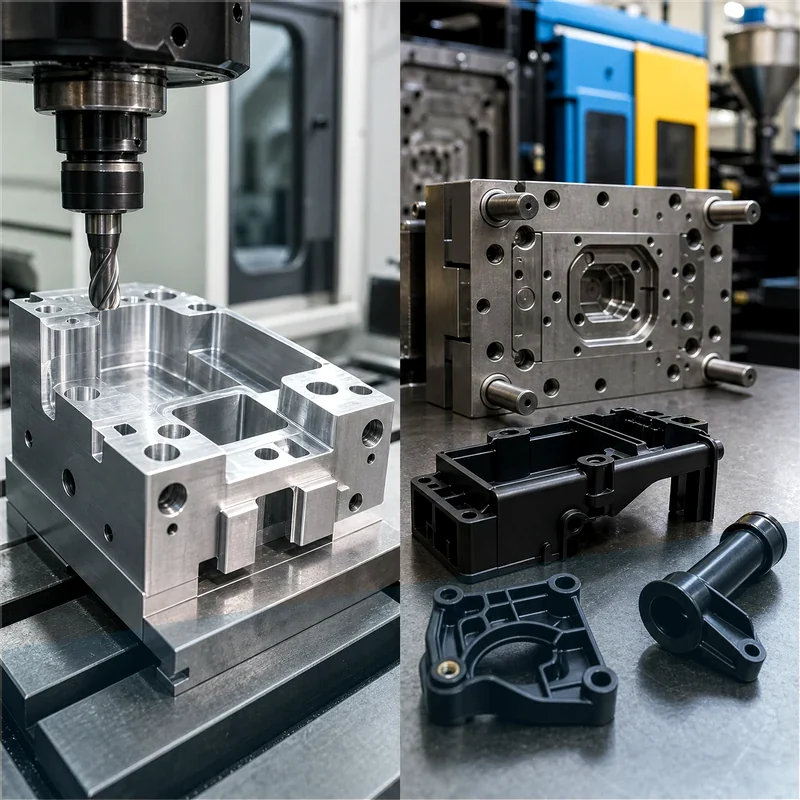
Any machining of samples for diagnosis should preserve the defect evidence and sample identity. A machined prototype can help assess fit, but it cannot prove the molding process is free of internal voids.

Verify the Correction Beyond the First Good Shot

Define success before running the confirmation lot. Check the internal defect with the chosen method and verify that the correction has not created flash, sink, warpage, unacceptable dimensions, or a new cosmetic issue. Include all relevant cavities and agreed operating conditions.

  • Compare samples against the original defect map.
  • Record the final approved process and material condition.
  • Repeat the critical functional and dimensional checks.
  • Assess startup or interruption conditions where relevant.
  • Establish lot disposition and a reaction plan if the defect returns.

When requesting help with mechanical interfaces or prototype components, send MTSPi the drawing, defect photographs, and acceptance criteria through the technical inquiry page. Keep the molding-process investigation with the responsible molder and material specialists.

Frequently Asked Questions

Will increasing pressure always remove bubbles?

No. Gas pockets and shrinkage voids have different mechanisms, and pressure changes may introduce other defects. Diagnose first.

Are internal bubbles only a cosmetic issue?

No. Depending on location and application, internal defects can affect strength, sealing, or durability even if the surface looks acceptable.

Should every resin receive the same drying cycle?

No. Use the specific grade supplier’s requirements and verify the condition of material at the machine.

Does one clear sample prove the fix?

No. Confirm the agreed batch, cavity coverage, inspection method, and process conditions before releasing production.

Technical reference basis: BASF Injection Molding Troubleshooter and engineering-thermoplastic defect guidance; Protolabs moldability guidance on thick sections. Diagnostic examples are illustrative and do not replace resin-specific processing instructions.

Categories
Blog Manufacturing Process Comparisons

3D Printing for Low-Volume Production: A Bridge-to-Molding Plan

3D printing can supply a low-volume production batch while an injection mold is being developed, provided the printed material, process, and inspection plan are approved for the actual use. A successful bridge-production plan defines what may ship, how each batch will be accepted, and when the program will change to molded parts. It is not simply a larger prototype order.

Decide What the Interim Parts Must Prove

Start with the consequence of failure. A display housing for an internal sales review does not have the same requirements as a customer-delivered enclosure exposed to heat, sunlight, cleaning chemicals, or repeated screw assembly. Write down the operating environment and the release authority before selecting a printer or material.

Intended use Useful acceptance evidence Do not assume
Appearance review Approved color and surface sample Printed texture reproduces molded texture
Assembly trial Mating-part checks and measured interfaces One fit check establishes production capability
Functional pilot Application-specific load and environmental tests A similarly named resin has identical properties
Customer shipment Approved specification, lot records, release inspection A prototype approval covers end-use shipment

Where certification or regulated use applies, confirm which manufacturing changes require additional qualification. A material datasheet alone does not establish compliance of a finished assembly.

Choose the Process Against the Failure Mode

SLA, SLS, MJF, and material-extrusion processes can address different combinations of appearance, geometry, material behavior, and throughput. Compare candidate processes using the same part and inspection criteria rather than a generic claim about the strongest or cheapest technology. The requirement-based printing process comparison provides a starting framework.

Orientation affects printability, support placement, finish, and dimensional results. The printer manufacturer’s validated guidance should inform the build setup. Keep supports away from critical cosmetic or mating surfaces where practical, and include cleaning and post-curing when the selected system requires them. Lock the approved build recipe before interpreting results from multiple deliveries as comparable.

Do not substitute an SLA resin described as ABS-like for molded ABS without checking the properties relevant to the application. Repeated flexing, long-term temperature exposure, creep, and chemical resistance may decide suitability even when both samples initially fit.

Compare Total Accepted-Part Cost

There is no universal quantity at which molding becomes cheaper. Use supplier quotations for the same revision and include tooling, setup, finishing, inspection, expected scrap, and delivery. A simple preliminary model is:

Break-even quantity = (mold tooling and setup cost minus print setup cost) / (accepted printed-part cost minus accepted molded-part cost).

This expression is useful only when the denominator is positive and the compared parts satisfy the same requirements. For an illustrative calculation, a tooling difference of $8,000 and a unit-cost difference of $16 gives 500 accepted parts. Those figures are invented planning inputs, not MTSPi pricing. A design revision that changes the tool, or a finishing operation omitted from one quotation, can invalidate the comparison.

Separate economics from availability. Printing may remain appropriate for a time-critical interim batch even when molding has a lower eventual unit cost. For a broader quotation checklist, review the factors behind printing and scale-up cost.

Make Each Batch Traceable

Printed parts can have effective traceability; it must be specified and maintained. A useful traveler connects the part revision to material lot, machine, build identifier, approved orientation, post-processing records, inspection results, and release date. Decide whether individual serialization or batch identification is needed.

  • Approve a representative sample before the first production release.
  • Identify critical dimensions and how they will be measured.
  • Agree sampling frequency and the response to a failed check.
  • Record build or material changes before shipping affected parts.
  • Retain a reference sample when useful for later comparison.

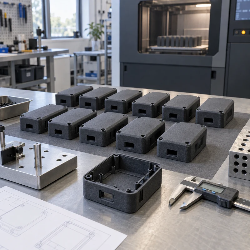
A hypothetical enclosure program might check mounting-hole location with a fixture, verify lid engagement with a mating part, and inspect the cosmetic face under agreed lighting. These checks answer different questions. Passing the visual inspection does not replace measuring the mounting interface.

Control the Transition to Molded Production

Maintain a revision-controlled comparison between the interim part and the molded design. Draft, ribs, wall thickness, gate locations, ejection marks, and shrinkage behavior require a molding-specific review. A printed prototype that assembles successfully does not prove that the same geometry is ready for tool release.

Close the bridge phase after the production process has passed its agreed qualification and supply can meet the schedule. Keep interim and molded stock identifiable when their material or performance differs. Establish disposition for remaining inventory instead of silently mixing both routes under an uncontrolled label.

When planning the surrounding mechanical parts, share the assembly model, tolerances, and expected production sequence with MTSPi through the project inquiry page. Confirm the proposed scope and process with the team rather than assuming every manufacturing route is available.

Frequently Asked Questions

Can printed bridge parts be sold to customers?

Yes, when the material and finished part are qualified for their intended use and the required approvals and traceability are in place. Prototype acceptance alone is insufficient.

Does bridge production always mean printing?

No. The term describes an interim production role. Machining, casting, or temporary tooling may also be suitable, depending on the part and schedule.

Are printed molds the same as directly printed parts?

No. Direct printing creates the component. A printed mold is tooling used to form a separate component, with its own limits on temperature, pressure, wear, and tool life.

Should every small batch avoid injection molding?

No. Required resin behavior, geometry, repeatability, and available tooling can make molding appropriate even for modest quantities.

Technical reference basis: Formlabs model-orientation guidance and injection-molding application documentation. Cost figures and inspection examples are illustrative planning examples, not production test data.

Categories
Blog Design, Cost & Sourcing

Medical Injection Molding Suppliers: An Evidence-Based Selection Guide

Choosing a medical injection molding supplier is an evidence exercise. A polished factory presentation does not establish that a particular production site can control your resin, tool, dimensions, contamination risks, and change history. The useful comparison is between the records each candidate can provide for the work you actually need.

Quick answer: Define the component’s function and acceptance criteria first. Screen suppliers for relevant quality-system scope, material traceability, tooling expertise, validation planning, and environmental controls. Then compare samples and documentation using the same drawing and test plan. Treat commercial price as one part of the decision.

Write a Project Brief Before Comparing Suppliers

A non-contact equipment cover, a fluid-path component, and an implantable component do not share the same requirements. Describe intended use, contact conditions where relevant, cleaning or sterilization exposure, assembly interfaces, quantities, and product life. Have the responsible quality and regulatory team define applicable obligations.

Include the exact resin grade or a controlled material-selection process. Define critical dimensions, appearance zones, packaging, and inspection methods. Suppliers cannot provide comparable proposals when each is making different assumptions about the scope.

An Evidence Matrix for Supplier Interviews

Area Evidence to request Follow-up question
Quality system Current certificate, site address, and scope where required Does the covered location perform this manufacturing step?
Material control Lot records, approved grades, storage and drying controls How is an unauthorized substitution prevented?
Tool and process DFM review, maintenance plan, sample process records How will cavity-to-cavity variation be evaluated?
Environment Defined controls and monitoring relevant to the component Where do parts travel after leaving the machine?
Measurement Inspection plan and suitable measurement methods Can the method reliably detect an out-of-limit part?
Changes Notification and approval procedure Which changes require customer approval before shipment?

Check Certification Scope Without Confusing It With Product Approval

A quality-system certificate can support supplier screening, but check its validity, scope, and manufacturing location. It does not establish approval of your device or prove that every process is suitable. Ask how the proposed work falls within the supplier’s controlled system and what records you will receive.

For U.S. finished-device manufacturers, FDA’s Quality Management System Regulation took effect on February 2, 2026 and incorporates ISO 13485:2016 by reference. Applicability depends on the organization’s role and product; a component supplier should not automatically be described as FDA approved. Confirm responsibilities for the actual supply arrangement.

Evaluate the Whole Handling Route

If controlled-environment molding is needed, map material entry, molding, trimming, inspection, assembly, and packaging. A clean machine area does not answer what happens during secondary handling. Define the contamination characteristics that matter and ask for the corresponding controls.

Keep environmental classification, product cleanliness, and sterility distinct. Establish the acceptance and verification approach with the responsible specialists. The cleanroom and standard molding comparison provides context for planning the production environment.

Make Validation Deliverables Part of the Quote

Discuss qualification and validation before issuing the tooling order. Agree on protocols, acceptance criteria, sample quantities, review responsibilities, and the records to be delivered. Installation, operational, and performance qualification may form part of the plan, depending on the process and applicable requirements.

Ask how the supplier will evaluate different cavities, material lots, and relevant process variation. A single attractive sample does not demonstrate sustained control. Where capability statistics are proposed, confirm that the measurement method and data set support the conclusion; do not accept a number detached from its method.

Review the Tooling and Drawing Together

Tool design affects gate vestiges, weld lines, ejector marks, parting lines, shrinkage, and assembly fit. Mark restricted areas on the drawing. Request an explanation of how critical features will be produced and measured, including the plan for correcting the tool after first samples.

For assemblies combining molded components with metal inserts or housings, define who owns the interface tolerances. Review the evaluation of precision component suppliers when the program also includes machined parts. Prototype fit checks can expose interface mistakes, but cannot establish production molding performance.

Set Traceability and Change Rules in Writing

Decide which records must connect the finished lot to the resin, colorant, tool, cavity, machine, inspection, and packaging batch. Define record retention and access. Use a sample record review during supplier assessment to check whether the trace can actually be followed.

  • Specify the policy for regrind and material substitutions.
  • Define approval of tool repairs that affect the component.
  • Include changes to subcontractors and production locations.
  • Agree how nonconforming lots will be segregated and reported.
  • Document the response and containment process for customer complaints.

Compare Commercial Terms After Technical Screening

Request separate prices for tooling, engineering work, qualification, routine production, inspection, and packaging. Clarify mold ownership, storage, maintenance, transfer documentation, and replacement inserts. Compare delivery commitments against realistic demand scenarios rather than only the smallest quoted unit price.

A practical selection method uses mandatory requirements first, then a documented scorecard. Do not average away a failed essential requirement with a low price. For two technically acceptable suppliers, compare the evidence quality, communication, capacity, and cost of sustaining the program.

Frequently Asked Questions

Does every medical component require a cleanroom?

Requirements depend on the component, intended use, subsequent processing, and acceptance criteria. Establish those requirements before specifying an environment.

Can a supplier certificate replace a product validation plan?

No. The certificate and the evidence for a particular product and process serve different purposes. Define the project-specific work and approval responsibilities.

What is the most useful first supplier meeting?

A review of one controlled drawing, its critical features, and the proposed evidence package. Concrete questions reveal more than a broad discussion of machine count.

This guide is a supplier-selection framework, not a statement that MTSPi holds a particular medical certification or operates a validated medical molding line.

Categories
Blog CNC Materials Manufacturing Process Comparisons Quality & Tolerances

Injection Molding Melt Temperature Guide: Materials, Settings, and Defect Control

Injection molding melt temperature controls viscosity, cavity filling, weld lines, surface replication, shrinkage, molecular orientation, and degradation. It is related to barrel-zone settings but is not identical to the displayed heater temperatures.

The correct range depends on polymer grade, additives, moisture, residence time, shear, screw design, machine size, part geometry, and mold temperature. Material supplier data is the starting point, followed by an approved process window.

Quick Answer

Use the resin manufacturer’s grade-specific range, dry the material correctly, measure actual melt when needed, and establish a stable window rather than one nominal number. Change temperature only after considering speed, pressure, back pressure, residence time, and mold conditions.

Comparison at a Glance

Factor Option A Option B
Low melt temperature High viscosity, short shots, weak weld lines Increase within approved window and verify drying
High melt temperature Degradation, gas, discoloration, flash Reduce heat or residence and check shear
Barrel display Shows zone control, not actual melt Verify with purge measurement or validated method
Shear heating Raises polymer temperature during plasticizing and fill Control screw speed and injection speed
Residence time Long exposure can damage resin Match shot size and cycle to machine capacity

Melt Temperature vs Barrel Temperature

Heater bands control barrel zones while the rotating screw generates shear heat. The polymer experiences a thermal history, so actual melt can differ from setpoints. Measure consistently and safely when troubleshooting.

Material Families

Amorphous and semi-crystalline polymers respond differently. ABS, PC, PMMA, PA, POM, PP, PE, PBT, and PEEK each need grade-specific conditions. Filled, flame-retardant, recycled, colored, and medical grades may use different limits.

Drying and Moisture

Hygroscopic materials can hydrolyze at processing temperature, reducing molecular weight and strength even if the part looks acceptable. Confirm dryer temperature, dew point, time, airflow, and material handling.

Defects Linked to Temperature

Low temperature can cause short shots, hesitation, poor knit lines, dull surfaces, and high pressure. Excessive temperature can cause splay, gas, odor, discoloration, flash, sticking, or brittleness. Similar defects can also come from moisture, venting, speed, or mold temperature.

  • Avoid changing several variables at once
  • Record actual conditions and lot
  • Check purge appearance and odor
  • Review residence time and shot utilization
  • Use a structured process study

Building a Process Window

Establish acceptable low and high boundaries for melt, fill speed, pack, cooling, and mold temperature. Validate critical dimensions and appearance across normal variation.

Design and Tooling Interaction

Thin walls, long flow paths, small gates, abrupt thickness changes, weak venting, and poor cooling may force an unnecessarily narrow thermal window. Improve part and mold design instead of relying on hotter material to solve every fill problem.

Quality Documentation

Record resin grade, lot, regrind policy, drying, machine, screw, zone settings, cycle, measured melt, mold temperature, pressure, and inspection results for controlled production.

Frequently Asked Questions

Is melt temperature the same as nozzle temperature?

No. Nozzle temperature is one setpoint; actual melt reflects barrel heating, shear, residence, and heat loss.

Should I use a universal temperature chart?

Charts provide orientation only. Use the exact resin supplier data and validate the process on the actual machine, mold, and part.

What happens if nylon is wet?

Moisture can create splay and hydrolytic degradation during melting, reducing strength. Proper drying and handling are essential.

Related MTSPi Resources

Categories
Blog Design, Cost & Sourcing Manufacturing Process Comparisons

How to Evaluate Injection Molding Companies in the USA: A 2026 Supplier Guide

Searching for injection molding companies in the USA produces long lists, but a supplier’s location or machine count does not show whether it fits your part. The useful question is whether its tooling, process control, material experience, quality system, capacity, communication, and commercial model match your program.

This guide provides a repeatable selection method for product teams. It does not rank companies by marketing visibility. Instead, it shows how to build a shortlist and compare evidence before committing to tooling.

Quick Supplier Selection Framework

Start with the part and program, not the supplier list. Define annual volume, resin, part size, cosmetic class, tolerance, regulatory needs, assembly content, target launch, and expected design changes. Eliminate suppliers that cannot support the required press size, resin family, documentation, or validation. Audit the remaining candidates using the same scorecard.

Eight Criteria That Matter Most

Criterion Evidence to request Risk if ignored
Tooling capability Mold design review, toolroom scope, maintenance plan Slow changes and recurring defects
Material experience Similar resin examples and drying controls Warp, splay, brittleness, color variation
Process control Documented windows and setup records Lot-to-lot inconsistency
Quality system Inspection plan, calibration, traceability Undetected defects and weak containment
Capacity Press availability and contingency plan Launch or replenishment delays
Engineering support DFM examples and mold-flow capability Tooling that locks in avoidable problems
Secondary operations Assembly, inserts, decorating, packaging Extra suppliers and handling risk
Commercial fit Transparent tooling ownership and change terms Unexpected fees and difficult transfers

Match the Supplier to Your Production Stage

A prototype or bridge program values speed, flexible tooling, and frequent engineering communication. A stable high-volume program values automation, cavity efficiency, preventive maintenance, material purchasing leverage, and dependable replenishment. A regulated program adds validation, traceability, change control, and record retention.

One supplier may be excellent at complex medical molding but expensive for a simple industrial housing. Another may run commodity resins efficiently but lack the engineering depth for optical parts or tight-tolerance inserts. Capability must be evaluated against the actual part family.

Tooling Questions to Ask Before Purchase

  • Who owns the mold, CAD data, and spare components?
  • Where will the mold be built, sampled, maintained, and stored?
  • What steel, insert, hot-runner, cooling, venting, and ejection approach is proposed?
  • How many shots is the quoted tool expected to support?
  • What is included in the sampling and approval cycle?
  • How are engineering changes priced and documented?
  • Can the mold be transferred, and is it compatible with another press base?

Quality and Validation

Request a control plan that links drawing requirements to measurement methods and sampling frequency. Critical dimensions may need a capability study. Cosmetic surfaces need an approved limit sample and controlled lighting. Materials may require certificates, lot traceability, moisture control, or regulatory declarations.

First Article Inspection is useful, but it is not the entire validation. A few acceptable parts do not prove a stable process. Ask how the supplier establishes the molding window and verifies performance across normal material, machine, cavity, and environmental variation.

Total Cost Beyond Piece Price

Cost component What to compare
Tooling Build, samples, spares, maintenance, modifications
Unit cost Resin, cycle time, cavities, labor, scrap
Quality Inspection, validation, containment, returns
Logistics Freight, packaging, inventory, emergency shipments
Change risk Revision speed and cost before design freeze
Program support Engineering time, reporting, communication

When a Hybrid Supply Chain Makes Sense

Some teams combine US molding with overseas tooling, CNC prototypes, or low-volume bridge production. This can balance response time and cost, but only when ownership, tolerances, data exchange, and responsibility are explicit. Before cutting a production mold, CNC-machined or printed prototypes can verify assembly, ergonomics, fastener access, and major dimensions.

Red Flags During Supplier Review

  • A quote arrives with no questions about draft, wall thickness, gate location, resin, or tolerance.
  • The supplier cannot explain how critical dimensions will be controlled.
  • Tool ownership and transfer terms are vague.
  • Every defect is treated as an inspection problem rather than a process problem.
  • Capacity claims are not supported by a launch or contingency plan.
  • Communication changes after the purchase order is issued.

Practical RFQ Package

Send a clean 3D model, controlled 2D drawing, expected volumes, resin specification, color and cosmetic standard, mating-part information, packaging needs, validation level, and launch schedule. Identify must-have requirements separately from preferences. This gives each supplier the same basis and makes quotations easier to compare.

Frequently Asked Questions

Should I choose the lowest injection molding quote?

Not automatically. Compare the included tool construction, sample cycles, process validation, maintenance, quality controls, logistics, and change terms. A low quote with weak assumptions can create a higher total program cost.

How many suppliers should receive an RFQ?

Three to five qualified suppliers is usually enough for a meaningful comparison. A very broad RFQ can consume time without improving the decision if candidates have not been screened for fit.

Can CNC machining reduce injection molding risk?

Yes. CNC prototypes in production-intent material can validate geometry, assembly, threads, flatness, and interfaces before mold steel is committed.

Related MTSPi CNC Resources

Categories
Blog Manufacturing Process Comparisons Quality & Tolerances

Cleanroom Injection Molding vs Standard Molding: Key Differences for Precision Parts

Cleanroom Injection Molding vs Standard Molding: Key Differences for Precision Parts is a practical manufacturing question because the answer affects cost, lead time, material behavior, inspection, and the path from prototype to production. For MTSPi CNC customers, the key is not simply naming a process, but understanding how the process connects with machined parts, fixtures, tolerances, surface requirements, and final assembly.

This guide explains cleanroom injection molding vs standard molding from an engineering and purchasing point of view. It is written for product developers, mechanical engineers, sourcing teams, and buyers who need clear decisions rather than generic process descriptions.

Quick Answer

Use standard molding for general industrial, consumer, and enclosure components where normal factory cleanliness is acceptable. Use cleanroom molding when particle contamination, biological burden, optical clarity, or medical validation can affect product performance.

Key Differences at a Glance

Point Option A Option B
Environment Controlled air and particle limits Normal manufacturing environment
Parts Medical, diagnostic, optical, sensitive electronics Industrial covers, brackets, caps, housings
Documentation Higher traceability and validation records Standard production records
Cost Higher operating and monitoring cost Lower cost for ordinary parts
Risk focus Contamination, packaging, handling Dimensions, cycle stability, cosmetic quality

How the Process Choice Affects Real Parts

A manufacturing method should be selected around the feature that actually controls function. Cosmetic surfaces, hidden support features, threads, bores, sealing faces, heat-transfer areas, and assembly datums do not carry the same risk. When those requirements are mixed together without priority, quotes become inconsistent and production becomes harder to control.

The safest workflow is to define the part requirement first, then match the process. A printed prototype may answer shape questions, a molded sample may answer appearance questions, and a CNC machined sample may answer tolerance, material, and functional questions. Many successful projects use more than one method before the final design is locked.

Design and Manufacturing Considerations

  • Specify cleanliness requirements only when they are functional or regulatory needs.
  • Separate cosmetic requirements from contamination requirements on the drawing.
  • Confirm resin compatibility with sterilization, cleaning agents, and final assembly conditions.
  • Plan inspection for critical dimensions, flash, particulates, and packaging damage.
  • Coordinate CNC inserts, machined fixtures, or threaded metal parts before mold validation.

Cost, Lead Time, and Risk Factors

Cost is driven by setup, tooling, material, machine time, inspection, finishing, and revision risk. A low unit price is not always the lowest project cost if it creates rework later. For prototypes and low-volume orders, flexibility can be more valuable than a process with a lower theoretical unit cost.

  • Use standard materials and standard feature sizes when they do not weaken the design.
  • Separate critical tolerances from general dimensions so the supplier knows where to focus.
  • Confirm surface finish and cosmetic requirements before production begins.
  • Avoid late changes to mounting holes, connector openings, datum faces, and threaded features.
  • Send CAD files and 2D drawings together when tolerances, threads, or finishes matter.

Quality Checks Before Production

A good quality plan checks the features that influence assembly and performance. Depending on the part, this may include dimensional inspection, thread gauges, surface roughness, flatness, perpendicularity, burr control, coating thickness, visual appearance, and fit with mating parts.

When This Topic Matters for CNC Buyers

cleanroom injection molding vs standard molding matters when a team is comparing prototype routes, validating a design, replacing a weak supplier, or trying to reduce manufacturing cost without damaging function. The best choice is usually the process that answers the current engineering question with the least unnecessary risk.

MTSPi CNC Engineering Notes

MTSPi CNC supports precision CNC milling, turning, rapid prototyping, low-volume production, finishing, and inspection for custom parts. If your project uses molding, casting, welding, PCB assemblies, or 3D printing, CNC machining can still be important for datums, holes, threads, sealing faces, fixtures, and production-ready prototypes.

Frequently Asked Questions

Can this process replace CNC machining?

Sometimes it can replace CNC for non-critical geometry, but CNC is often still needed when tight tolerances, real engineering material, threads, flat sealing faces, or precise mating features are required.

What files help MTSPi CNC review a project?

STEP or STP files are useful for geometry. A 2D drawing is important for tolerances, materials, threads, surface finish, inspection requirements, and notes that are not obvious from the CAD model.

How do I reduce manufacturing risk?

Define critical features, avoid unnecessary tight tolerances, confirm material and finish requirements, and use prototypes to validate assembly before committing to higher-volume tooling or production.

Related MTSPi Resources

Request A Quote

We'll Send You Back with Price Immediately!

DEC 1-31

XMAS SPECEIL

Up to

40% off

Cleanroom Injection Molding vs Standard Molding: Key Differences for Precision Parts

We'll Send You Back with Price Immediately!