Categories
Surface Finishing

Does Nickel Rust? Nickel Corrosion, Plating, and CNC Part Applications

Nickel does not rust in the strict chemical sense because rust is iron oxide, and pure nickel does not contain iron. However, nickel can still corrode, tarnish, pit, or lose its surface appearance under certain environments. Nickel-plated steel can also show rust if the plating is damaged and the steel underneath is exposed.

For CNC machined parts, the practical question is not only whether nickel rusts. Buyers need to know when nickel, brushed nickel, satin nickel, and nickel-plated steel are suitable, how corrosion starts, and what finishing choices can improve durability. This guide rewrites the topic from a manufacturing and material-selection point of view for MTSPi CNC / MEITESI customers.

Quick Answer

Pure nickel does not rust like carbon steel because rust specifically refers to iron oxide. Nickel can still corrode, especially in harsh chemicals, salt environments, acidic conditions, or damaged coatings. Nickel-plated steel may rust when scratches, pores, or worn edges expose the steel substrate. Brushed nickel and satin nickel finishes can resist corrosion well indoors, but outdoor durability depends on the base material, plating quality, coating thickness, and maintenance.
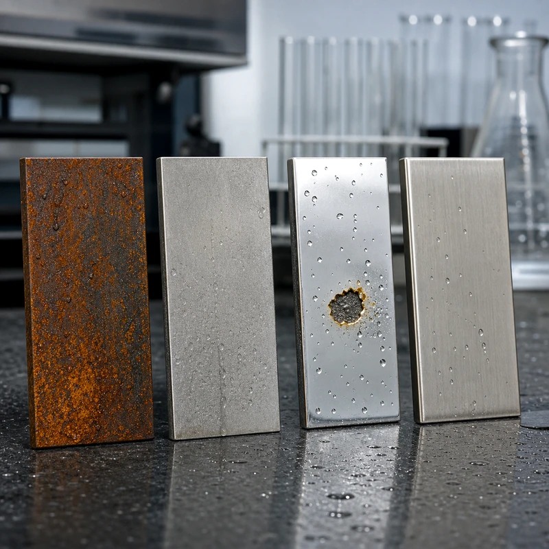
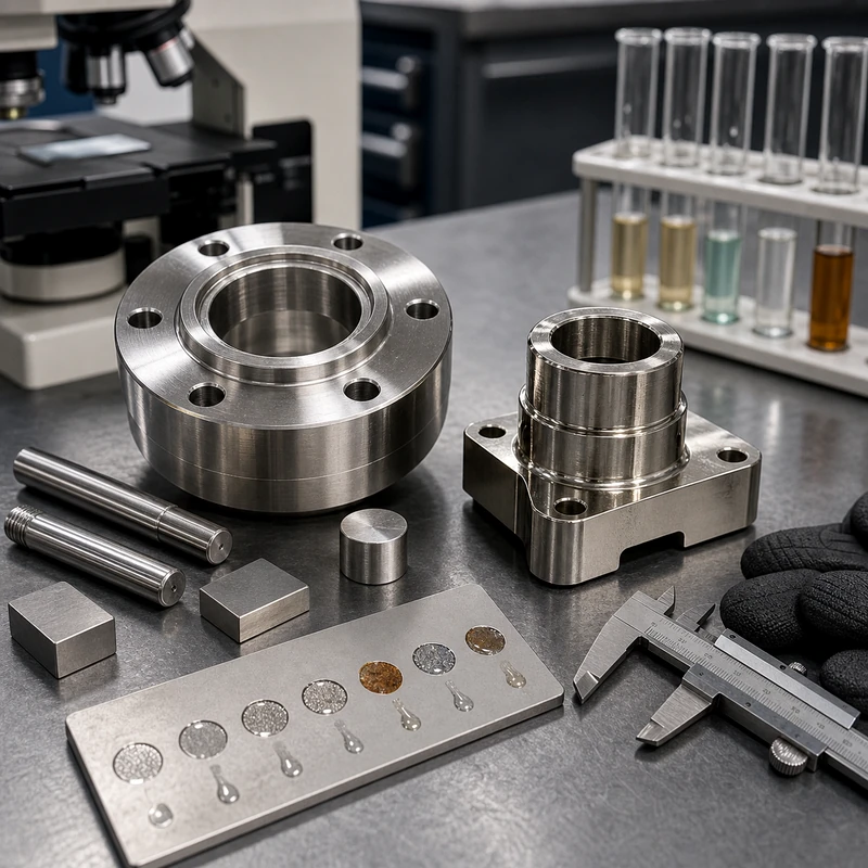
Rust and nickel corrosion comparison on metal samples

What Exactly Is Rust?

Rust is a specific corrosion product that forms when iron or steel reacts with oxygen and moisture. It is usually reddish-brown or orange because iron oxide forms on the surface. Since nickel is not iron, pure nickel does not create the same orange iron-rust layer.

That does not mean nickel is completely immune to surface change. Nickel can oxidize, discolor, pit, or react with chemicals. In many normal environments, nickel forms a thin protective surface film that slows further corrosion. This is why nickel and nickel plating are often used for decorative and protective finishes.

Does Nickel Rust?

Pure nickel does not rust in the way carbon steel rusts. It has good corrosion resistance in many indoor and mildly corrosive environments. This makes nickel useful for plated hardware, electrical contacts, decorative finishes, machined components, and parts that need both appearance and moderate corrosion protection.

The important limitation is that nickel can still corrode. In chloride exposure, acidic media, high temperature, or aggressive chemicals, nickel may pit or degrade. If nickel is applied as a plating layer on steel, any damage to the plating can allow the steel underneath to rust.

Types of Nickel Corrosion

Nickel corrosion can appear in different ways. Surface tarnish may make the finish look dull. Pitting can create small localized holes in aggressive environments. Galvanic corrosion can occur when nickel is connected to a different metal in the presence of an electrolyte. Plated parts can also fail at pores, edges, scratches, or thin coating areas.

For machined parts, the risk depends on the base material, surface preparation, plating thickness, post-treatment, environment, and whether the part is scratched during assembly or use.

Does Nickel-Plated Steel Rust?

Nickel-plated steel can rust if the nickel layer is thin, porous, cracked, scratched, or worn through. The nickel layer protects the steel only while it remains continuous enough to block moisture and oxygen from reaching the substrate. Once steel is exposed, normal iron rust can form at that damaged area.

This is especially important for threaded parts, edges, press-fit surfaces, and components that see repeated abrasion. If corrosion resistance is critical, buyers should define the plating specification, thickness, base material, and service environment clearly.
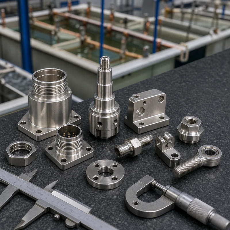
Nickel plated machined parts and CNC hardware

Does Brushed Nickel Rust?

Brushed nickel is usually a finish texture, not a base material by itself. It may be applied over brass, steel, zinc alloy, stainless steel, or another substrate. Whether it rusts depends on what is underneath and how well the finish is protected.

A brushed nickel finish on a non-ferrous base may not rust, but it can still tarnish or discolor. Brushed nickel over steel can rust if the coating is damaged or thin. For functional CNC parts, the substrate and coating specification matter more than the appearance name.

Does Satin Nickel Rust?

Satin nickel is also a surface appearance. It can provide good corrosion resistance indoors when the plating is properly applied. In wet, salty, or abrasive environments, satin nickel over steel may rust at damaged edges or scratches. The finish can also dull over time if exposed to harsh cleaners or outdoor conditions.

Does Brushed Nickel Rust Outside?

Outdoor use is more demanding because rain, humidity, UV exposure, salt, temperature cycling, and pollutants can attack the surface. Brushed nickel hardware may survive well in sheltered environments, but it is not automatically rust-proof outdoors. Nickel-plated steel is more vulnerable if the coating is damaged.

For outdoor CNC components, stainless steel, aluminum with anodizing, suitable nickel alloy, or a specified plating system may be a better choice depending on strength, appearance, and cost requirements.
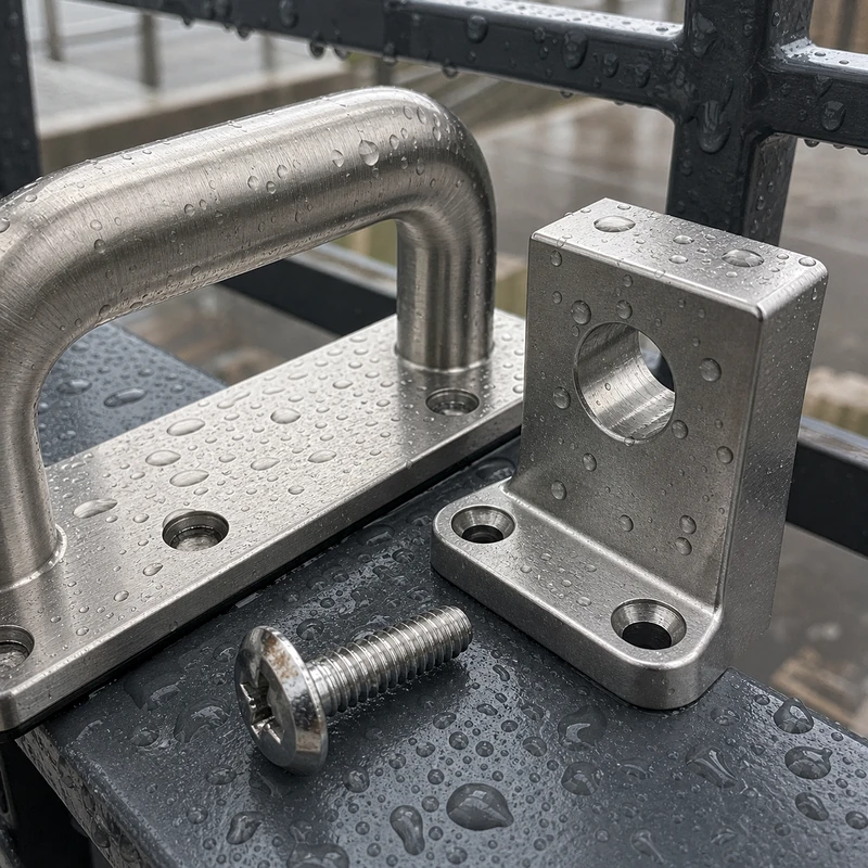
Brushed nickel and satin nickel hardware exposed to moisture

Nickel vs Common Metals: Rust and Corrosion Comparison

Material or finish Does it form red rust? Typical corrosion behavior CNC part note
Pure nickel No Can tarnish, oxidize, or pit in aggressive environments. Useful where moderate corrosion resistance, metallic appearance, or nickel alloy properties are needed.
Nickel-plated steel Only if steel is exposed Plating protects the surface, but scratches, pores, or worn edges can allow steel rust. Specify plating type, thickness, masking, and service environment if rust resistance matters.
Carbon steel Yes Forms red-orange iron oxide quickly when exposed to moisture and oxygen. Needs coating, plating, oiling, painting, or controlled storage for corrosion protection.
Stainless steel Usually no Can pit or stain in chloride, acid, or poor passivation conditions. Good option for corrosion-resistant machined parts, but grade selection matters.
Aluminum No Forms aluminum oxide; can pit in salt or harsh chemicals. Anodizing can improve surface protection and appearance.
Brass and copper No Can tarnish or develop patina rather than red rust. Often chosen for conductivity, fittings, appearance, or corrosion behavior.

What Metal Is Rust Proof?

No engineering metal is completely immune to all corrosion, but some metals do not form traditional iron rust because they contain little or no iron. Aluminum, copper, brass, bronze, titanium, nickel, and many stainless steels behave differently from carbon steel. They may oxidize, tarnish, pit, or discolor rather than form orange rust.

For CNC part sourcing, it is better to ask which material is suitable for the environment rather than asking whether it is rust-proof. Chemical exposure, temperature, salt, contact metals, cleaning method, and appearance requirements all affect the decision.

What Is Nickel?

Nickel is a silvery metal known for corrosion resistance, toughness, and usefulness in alloys and plating. It is often used in stainless steels, superalloys, batteries, coatings, and decorative finishes. In CNC manufacturing, nickel may appear as a base alloy, a plating layer, or an alloying element in stainless steel and high-performance materials.

Nickel is also used when parts need a bright appearance, wear resistance, solderability, or moderate corrosion protection. However, nickel allergies, regulatory requirements, and application environment should be considered for consumer-facing components.

What Is the Density of Nickel?

The density of nickel is about 8.9 g/cm3. It is heavier than aluminum and many steels are in a similar range depending on alloy. Density matters when weight, balance, shipping cost, or product feel is important.

Is Nickel Magnetic?

Nickel is ferromagnetic at room temperature, so pure nickel can be attracted to a magnet. However, magnetism in finished parts depends on alloy composition, heat treatment, coating thickness, and the substrate. A nickel finish over a non-magnetic base may behave differently from a solid nickel alloy.

How Fast Does Nickel Rust or Corrode?

Pure nickel does not rust like iron, so there is no single rusting speed. Corrosion speed depends on environment. In dry indoor air, nickel may remain stable for a long time. In salt spray, acids, or damaged plated surfaces, corrosion can happen much faster. Nickel-plated steel may rust quickly at scratches if moisture reaches the steel substrate.

Practical Applications of Nickel in Machined Parts

  • Decorative and protective plating for machined steel or brass parts
  • Electrical contacts and connector components
  • Wear-resistant surfaces on small hardware
  • Corrosion-resistant parts in mild service environments
  • Alloying element in stainless steel and nickel-based alloys
  • Prototype or low-volume parts that need a bright metallic finish

For custom CNC projects, MTSPi CNC can review material and finish choices for CNC metal parts, aluminum CNC machining, and stainless steel CNC machining.

How to Choose Nickel or Nickel Plating for CNC Parts

Choose nickel or nickel plating when the part needs a bright finish, moderate corrosion protection, improved wear resistance, or a specific electrical/contact property. Avoid vague finish names when performance matters. Instead, specify the base material, plating type, coating thickness, appearance, masking areas, and service environment.

If a part will be used outdoors, in salt spray, or in contact with chemicals, ask for a finish review before production. A small design or coating change may prevent corrosion problems later.

Conclusion

Nickel does not rust like carbon steel because rust is iron oxide. But nickel can corrode, and nickel-plated steel can rust when the coating is damaged or incomplete. Brushed nickel and satin nickel finishes can perform well indoors, but outdoor or harsh environments require careful base material and coating selection.

For CNC machined parts, the best choice depends on function, appearance, environment, cost, and inspection needs. MTSPi CNC / MEITESI can help review whether nickel, nickel plating, stainless steel, aluminum, or another finish is the right route for your project.

FAQ

Does pure nickel rust?

No. Pure nickel does not form iron rust because it does not contain iron. It can still oxidize or corrode in certain environments.

Can nickel-plated steel rust?

Yes. If the nickel plating is scratched, porous, thin, or worn through, the steel underneath can rust.

Is brushed nickel good for outdoor use?

It depends on the base material, coating quality, and environment. Brushed nickel over steel can rust if damaged, especially outdoors or near salt.

Is nickel magnetic?

Pure nickel is magnetic at room temperature, but finished part magnetism depends on alloy, coating, and substrate.

What should I specify for nickel-plated CNC parts?

Specify base material, plating type, coating thickness, appearance, masking areas, service environment, and any corrosion or inspection requirements.
Categories
CNC Materials

Text Milling: CNC Engraving for Machined Parts

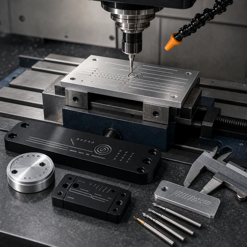
Text milling is a CNC machining method used to engrave names, part numbers, serial codes, arrows, scale marks, logos, or other shallow identification features onto machined parts. Instead of printing or applying a label, the text is cut directly into the material with a small engraving cutter, end mill, or V-bit.

For custom parts, text milling can make identification more durable and professional. It is useful for prototypes, fixtures, panels, aluminum housings, plastic covers, control plates, and components that need traceability. This guide explains how text milling works, what affects font and size choices, which materials are suitable, and how to specify engraved text in an RFQ for MTSPi CNC / MEITESI.

Quick Answer

Text milling means using CNC tools to cut text or marking features into a part surface. The best results usually come from simple fonts, adequate character size, enough stroke width, flat or accessible surfaces, and material that can hold clean edges. Buyers should provide exact text, font preference, location, depth, size, and whether the engraving is cosmetic, functional, or traceability-related.

What Is Text Milling?

Text milling is a subtractive marking process. The CNC machine removes a small amount of material to form letters, numbers, symbols, or graphic marks. The mark may be shallow and cosmetic, or it may be deep enough to remain visible after handling, coating, or repeated use.

Unlike laser marking or printing, text milling creates a physical groove. This can be helpful when the part needs a durable mark, when labels may peel off, or when the text must be part of the machined geometry.

Common Uses for Text Milling

  • Part numbers and revision marks on prototypes
  • Serial numbers and traceability markings
  • Labels on control panels, covers, and plates
  • Orientation arrows, scale marks, and assembly notes
  • Brand marks or simple logos on machined parts
  • Fixture identification and shop-floor tooling labels

Text milling is common on aluminum plates, stainless steel parts, brass components, plastic panels, engineering fixtures, and low-volume custom parts where permanent identification is useful.

Text Milling Font Type

Simple fonts machine better than decorative fonts. A clean sans-serif font is usually easier to engrave because the strokes are consistent and the toolpath is predictable. Very thin, script-style, or highly detailed fonts can require smaller tools, slower cutting, and more finishing work.

For functional marking, readability matters more than style. If the text must be inspected, scanned, or read by operators, choose a font with clear spacing and avoid crowded characters. Single-line engraving fonts can be efficient for simple marking, while outline fonts may be used when the appearance needs more visual weight.

Text Milling Font Size

Font size should be large enough for the cutter to create clean strokes. Very small letters require very small tools, and small tools are more fragile. Tiny text may also become unreadable after bead blasting, anodizing, powder coating, polishing, or normal wear.

A practical text size depends on material, tool diameter, engraving depth, surface finish, and viewing distance. For small parts, shallow fine text may be acceptable. For industrial labels, larger letters with generous spacing are safer.

Design factor Why it matters
Character height Controls readability and tool size.
Stroke width Must be compatible with the cutter diameter.
Engraving depth Affects visibility, burrs, cycle time, and coating behavior.
Letter spacing Prevents characters from blending together after machining or finishing.

Text Milling Materials

Text milling can be used on many materials, but the result depends on hardness, chip behavior, burr formation, surface finish, and the final coating or treatment. The same text geometry may need different tools and depths on aluminum, stainless steel, plastic, and brass.

Metals

Aluminum is one of the easiest materials for CNC text milling. It cuts cleanly and can produce sharp marks, especially before anodizing. Stainless steel is more durable but harder on tools and may need careful cutting parameters to avoid burrs or poor finish. Brass can engrave cleanly, while copper may be more difficult because it can be gummy.

For metal parts, consider whether the text will be visible after anodizing, passivation, bead blasting, polishing, black oxide, or powder coating. A mark that looks clear before finishing may become subtle after a thick coating.

Plastics

Engineering plastics such as POM, ABS, PEEK, nylon, acrylic, and polycarbonate can be engraved, but heat control is important. Some plastics can melt, smear, or leave fuzzy edges if the tool is dull or the feed and speed are poorly chosen.

Plastic parts may need a slightly different engraving depth and tool shape than metal parts. For visible panels, a clean surface finish and burr control are especially important.

Wood, Composites, and Other Materials

Text milling can also be used on wood, composite panels, and some specialty materials. These materials may behave differently from metal. Fibers, layers, resin content, and dust control can affect the final result. For composites, tool wear and edge quality should be reviewed before production.

Design Tips for CNC Text Milling

  • Use simple, readable fonts whenever possible.
  • Keep letters large enough for the chosen cutter.
  • Avoid placing text too close to edges, holes, ribs, or clamping areas.
  • Specify engraving depth if visibility or coating is important.
  • Confirm whether the text should be milled before or after surface finishing.
  • Provide vector artwork for logos instead of low-resolution images.
  • Use a flat or accessible surface so the cutter can reach the text cleanly.

Text Milling vs Laser Marking

Text milling physically cuts grooves into the part, while laser marking changes the surface with light and heat. CNC milling is useful when a mark needs depth, when the part is already being machined, or when the mark should be part of the geometry. Laser marking may be faster for fine serial numbers, QR codes, and high-volume marking on suitable materials.

The best method depends on material, text size, durability, appearance, and production quantity. For low-volume machined components, milling the text during the CNC process can be convenient and durable.

How to Specify Text Milling in an RFQ

To avoid mistakes, the RFQ should include the exact text, location, orientation, font or artwork file, character height, depth, and whether the text is cosmetic or functional. If the part will be anodized, coated, or blasted, state whether the text must remain visible after finishing.

For custom machined parts, MTSPi CNC can review text placement along with CNC machining drawings, material choice, tolerances, and finishing requirements. Related processes may include CNC milling service and CNC machining aluminum parts.

Common Mistakes to Avoid

  • Using text that is too small for the cutter and material.
  • Choosing decorative fonts that are hard to machine cleanly.
  • Forgetting that coating or blasting may reduce text visibility.
  • Placing text where clamps, curved surfaces, or tool access make machining difficult.
  • Sending raster artwork when clean vector geometry is needed.
  • Not specifying whether the mark is cosmetic, traceability-related, or functional.

Conclusion

Text milling is a practical way to add durable identification, labels, symbols, serial marks, or simple branding to machined parts. The best results come from clear fonts, realistic character size, accessible surfaces, suitable tools, and early communication about finishing and visibility.

If your part needs milled text or engraved marking, send MTSPi CNC / MEITESI the model, drawing, exact text, artwork file, material, finish, and quantity. A quick review can confirm the right engraving size, depth, cutter, and machining sequence.

FAQ

What is text milling?

Text milling is the process of engraving letters, numbers, symbols, or marks into a part using CNC cutting tools.

What font is best for CNC text milling?

Simple sans-serif or single-line engraving fonts are usually best because they are easier to machine and read.

Can text milling be used on aluminum?

Yes. Aluminum is one of the most common materials for text milling because it machines cleanly and can hold clear engraved marks.

Can CNC text be added after anodizing?

It depends on the required appearance. Text can be milled before finishing or sometimes after finishing, but the sequence changes color, edge appearance, and corrosion protection.

What files should I send for a logo or custom mark?

Send vector artwork such as DXF, AI, SVG, or clean CAD geometry whenever possible. Low-resolution images are not ideal for precise CNC engraving.

Categories
CNC Materials

What Can a 5-Axis CNC Machine Do? Common Questions Answered

A 5-axis CNC machine can cut complex parts from several angles without repeatedly removing and reclamping the workpiece. It can machine angled holes, multi-sided features, sculpted surfaces, deep pockets, complex aluminum housings, aerospace-style brackets, medical components, molds, fixtures, and other precision parts that would be difficult or slow on simpler machines.

However, a 5-axis machine cannot solve every design problem. Tool access, cutter shape, material behavior, workholding, programming, collision clearance, tolerances, and inspection still matter. This guide answers common questions about what a 5-axis CNC machine can and cannot do for buyers working with MTSPi CNC / MEITESI.

Quick Answer

A 5-axis CNC machine can move the cutting tool or workpiece in three linear axes and two rotary axes. This lets the cutter reach the part from different directions, reduce setups, improve access to angled features, and machine complex geometry more efficiently. It is useful for parts with angled faces, compound surfaces, tight datum relationships, and features on several sides.

What Can a 5-Axis CNC Machine Do?

The main advantage of 5-axis machining is access. The machine can tilt and rotate so the cutter approaches the part from a better angle. This helps with features that are not straight up and down, surfaces that curve in several directions, and parts that would otherwise require many setups.

Common capabilities include machining angled holes, contoured surfaces, pockets on tilted faces, undercut-style access in some geometries, multi-side features, complex aluminum parts, shorter-tool finishing, and parts where several critical features must stay aligned.

Capability Why 5-axis helps
Angled holes and faces The tool can be oriented toward the feature instead of forcing a separate setup.
Complex surfaces Tool angle can follow curved geometry for better reach and finish.
Multi-sided parts Fewer reclamping steps can improve datum relationships.
Deep or difficult access Tilting the tool can reduce tool length and improve rigidity.

Can a 5-Axis CNC Machine Cut Triangle Holes?

A 5-axis CNC machine can machine triangular pockets, triangular profiles, and three-sided openings if the geometry allows tool access. But a perfectly sharp internal triangular corner cannot be milled directly with a round cutter. Milling tools leave a radius in internal corners.

If a drawing requires sharp internal corners, the supplier may need EDM, broaching, a design change, or an accepted corner radius. For most functional designs, adding a practical internal radius is faster and more economical.

Can a 5-Axis CNC Machine Cut Angled Holes?

Yes. Angled holes are one of the common reasons to use 5-axis machining. The machine can tilt the part or tool so drilling, boring, or milling is aligned with the hole direction. This can reduce special fixtures and improve positional control.

The exact result depends on hole diameter, depth, material, tool length, surface angle, and whether the hole is drilled, interpolated, bored, tapped, or reamed. Deep angled holes still need careful tool selection and chip evacuation.

Can a Horizontal Machining Center Perform 5-Axis Machining?

Some horizontal machining centers can perform 5-axis or 3+2 machining if they include the right rotary axes, trunnion, rotary table, or tilting head configuration. However, not every horizontal machining center is a 5-axis machine. The actual capability depends on the machine design.

A buyer should not judge capability only by the machine category name. The important questions are how many controlled axes the machine has, whether it supports simultaneous movement, what the rotary limits are, and whether the post-processor and CAM workflow are proven.

Can a 5-Axis CNC Machine Handle Complex Aluminum Parts?

Yes. Complex aluminum parts are one of the strongest applications for 5-axis machining. Aluminum is often used for aerospace-style brackets, housings, frames, heat sinks, fixtures, lightweight structures, and prototype components. 5-axis access can reduce setups and improve surface finish on angled or curved features.

For aluminum, the design should still avoid unnecessarily thin walls, deep narrow cavities, and sharp internal corners. Good DFM review can reduce vibration, distortion, and finishing cost. For related guidance, see how to design parts for 5-axis CNC machining.

5-Axis CNC Machining Has Limitations

A 5-axis machine is powerful, but it cannot ignore physics. Cutters are still round. Tools still need clearance. Workpieces still need secure clamping. Thin walls can still move. Deep narrow features can still require long tools. Very tight tolerances still require stable processes and inspection.

The machine also depends on programming and simulation. Complex five-axis work needs CAM software, collision checking, a correct post-processor, and experienced setup. For programming details, see what is 5-axis CNC programming.

When Should You Choose 5-Axis CNC Machining?

Choose 5-axis machining when the part geometry needs angled access, multi-side machining, complex surfaces, or fewer setups for critical relationships. It is especially useful when repeated 3-axis setups would add too much alignment risk, tool reach, or manual handling.

Do not choose 5-axis machining just because it sounds advanced. If a part is a simple plate, bracket, or block with accessible top-face features, standard CNC milling service may be more economical. For round parts, CNC turning service may be better.

Examples of Parts Suited for 5-Axis Machining

  • Complex aluminum housings with angled ports or faces
  • Aerospace-style brackets and lightweight structures
  • Medical components with precise curved surfaces
  • Impeller-like parts and sculpted surfaces
  • Molds, fixtures, and prototypes with multiple critical sides
  • Parts where one setup can improve datum control

How MTSPi CNC Handles Complex 5-Axis CNC Parts

MTSPi CNC reviews the model, drawing, material, tolerance, finish, and quantity before deciding whether a part should use 3-axis, 4-axis, 3+2 indexed, simultaneous 5-axis, or a mixed strategy. The right process depends on the part, not only the machine label.

For some features, indexed 3+2 machining is stable and cost-effective. For complex surfaces, simultaneous 5-axis machining may be needed. For many parts, a mixed process gives the best balance of cost, accuracy, and surface quality. See 3+2 axis vs simultaneous 5-axis machining for more detail.

RFQ Checklist for 5-Axis Parts

RFQ item Why it matters
STEP file Allows tool access, setup, and CAM review.
2D drawing Defines datums, tolerances, threads, finish, and inspection needs.
Material and quantity Affects tooling, fixture strategy, machining time, and price.
Critical features Helps decide where 5-axis access and inspection control are most important.

Conclusion

A 5-axis CNC machine can do much more than machine from five directions. It can reduce setups, improve access to angled features, support complex surfaces, help with multi-sided parts, and improve datum control on difficult geometry. But it still needs good design, practical tooling, stable workholding, CAM programming, and inspection.

If you have a complex CNC part, send MTSPi CNC / MEITESI the model, drawing, material, quantity, finish, and inspection requirements. A process review can confirm whether 5-axis machining is the right choice or whether a simpler route can achieve the same result.

FAQ

Can a 5-axis CNC machine make any shape?

No. It can machine many complex shapes, but tool geometry, access, workholding, material behavior, and inspection still limit what is practical.

Can 5-axis CNC cut sharp internal corners?

Not with standard milling tools. Internal corners usually have a radius because cutters are round. Sharp corners may require EDM or a design change.

Is 5-axis CNC only for aerospace parts?

No. It is common in aerospace, but it is also useful for medical parts, molds, fixtures, prototypes, aluminum housings, and precision multi-sided components.

Does 5-axis machining always cost more?

The machine rate may be higher, but total cost can be lower if it reduces setups, shortens tools, improves finish, or lowers scrap risk.

What files are needed for a 5-axis machining quote?

Send a STEP file, 2D drawing, material grade, quantity, finish requirement, critical tolerances, and inspection notes.

Categories
Machine Tools & Programming

What Is 5-Axis CNC Programming? Toolpaths, CAM, and Simulation

5-axis CNC programming is the process of creating safe, accurate toolpaths for a CNC machine that can move in three linear axes and two rotary axes. It is used when a part needs angled features, complex surfaces, fewer setups, or tool access that is difficult on a standard 3-axis machine.

Good programming is critical because 5-axis machining involves more than moving the cutter around a model. The programmer must control tool orientation, avoid collisions, choose practical cutting strategies, verify machine motion, and output code that matches the exact machine and control. This guide explains the core ideas for buyers, engineers, and manufacturing teams working with MTSPi CNC / MEITESI.

Quick Answer

5-axis CNC programming uses CAM software and machining knowledge to define how a 5-axis CNC machine cuts a part. It includes toolpath creation, tool axis control, collision checking, simulation, post-processing, and setup verification. The goal is to machine complex features accurately while protecting the machine, tool, fixture, and workpiece.

What Is 5-Axis CNC Programming?

In a 5-axis CNC machine, the cutter or workpiece can move along X, Y, and Z while also rotating around two axes. Programming tells the machine where the tool tip should go and how the tool should tilt during machining. This allows the cutter to approach the part from different angles instead of being limited to straight-down cutting.

The program is usually created in CAM software from a 3D CAD model and 2D drawing. The CAM file defines cutting tools, toolpaths, speeds, feeds, stepovers, tool orientation, retract moves, clearance, and machining order. The final code is generated through a post-processor for a specific machine.

Why Is 5-Axis Programming More Difficult Than 3-Axis Programming?

3-axis programming mainly controls the cutter position in three linear directions. 5-axis programming must also control tool angle, rotary axis movement, machine limits, holder clearance, fixture clearance, and the relationship between the tool and part throughout the cut. A small programming error can cause a collision or poor surface finish.

The programmer must think about machine kinematics, not only part geometry. Two different 5-axis machines may need different code for the same part because their rotary axes, table layout, control system, travel limits, and post-processors can differ.

3+2 Programming vs Simultaneous 5-Axis Programming

There are two common programming strategies. In 3+2 programming, the machine rotates to a fixed angle, locks that position, and then cuts with three linear axes. This is useful for angled faces, holes, and multi-side features that can be reached from stable indexed positions.

In simultaneous 5-axis programming, the linear and rotary axes move together while cutting. This is useful for flowing surfaces, undercuts, turbine-style geometry, and features where the tool angle must change continuously. Simultaneous programming is more complex, but it can create surfaces and access that 3+2 cannot handle efficiently.

For a deeper comparison, see 3+2 axis vs simultaneous 5-axis machining.

Main Steps in 5-Axis CNC Programming

Step What happens Why it matters
Review model and drawing Check geometry, datums, tolerances, material, and finish Prevents programming the wrong manufacturing intent
Choose strategy Decide 3+2, simultaneous, or mixed machining Controls cost, access, stability, and surface finish
Select tools Define cutter type, holder, length, diameter, and material Affects rigidity, reach, finish, and tool life
Create toolpaths Generate roughing, finishing, drilling, and rest machining paths Defines how material is removed
Simulate and post Check collisions and output machine-specific code Reduces crash risk and setup errors

Tool Axis Control Matters a Lot

Tool axis control defines how the cutter tilts relative to the part surface. A good tool angle can reduce tool stick-out, improve surface finish, avoid holder interference, and help the cutter reach difficult geometry. A poor tool angle can gouge the part, create chatter, or collide with the fixture.

In simultaneous 5-axis machining, tool orientation may change continuously. The CAM strategy must keep that motion smooth enough for the machine to run without sudden rotary moves, poor finish, or feedrate problems.

Collision Avoidance in 5-Axis Programming

Collision avoidance is one of the most important parts of 5-axis programming. The programmer must check the cutter, holder, spindle, fixture, clamps, rotary table, stock, and finished part. Simulation should include the real tool assembly and workholding whenever possible.

Collision checking is especially important for deep cavities, tall walls, short clearances, tilted tools, and expensive materials. A verified program protects the machine and reduces the chance of scrapped parts.

Why the Post-Processor Is So Important

A post-processor converts CAM toolpaths into CNC code for a specific machine. In 5-axis work, the post-processor must correctly handle rotary axis direction, limits, tool center point control, retract moves, feedrates, work offsets, and machine-specific commands.

A toolpath that looks correct in CAM can still fail if the post-processor is wrong. This is why 5-axis programming should be connected to the actual machine model and control system, not treated as generic code.

Common 5-Axis CNC Programming Mistakes

  • Choosing simultaneous 5-axis when 3+2 indexed machining would be simpler and more stable.
  • Using tool angles that create holder or spindle interference.
  • Skipping accurate fixture and clamp modeling during simulation.
  • Using long tools when a better tilt strategy could allow shorter tools.
  • Ignoring machine rotary limits or singularity problems.
  • Applying tight tolerances without planning inspection and setup control.
  • Posting code without verifying it on the target machine configuration.

What CAM Software Is Used for 5-Axis Programming?

Many professional CAM systems can support 5-axis programming. The exact software matters less than whether the team can use it correctly for the machine, material, and part geometry. Important capabilities include multi-axis toolpaths, collision detection, stock simulation, tool libraries, machine simulation, post-processing, and NC verification.

For more about CAM planning, see 5-axis machining software.

When Do You Need Professional 5-Axis Programming?

Professional 5-axis programming is needed when the part has complex surfaces, angled features, deep access, expensive material, strict datum relationships, or high inspection risk. It is also important when a part must move from prototype to repeatable production.

If a part is simple, 3-axis or indexed machining may be enough. If the geometry is complex, the programming strategy should be reviewed before quoting and before material is cut.

How MTSPi CNC Handles 5-Axis CNC Programming

MTSPi CNC reviews the model, drawing, material, tolerance, finish, quantity, and inspection needs before choosing a programming strategy. The team considers whether the job should use 3-axis, 4-axis, 3+2 indexed machining, simultaneous 5-axis machining, or a mixed route.

The process includes CAM toolpath planning, tool and holder selection, workholding review, simulation, collision checking, post-processing, first-piece verification, and inspection planning. This helps turn complex geometry into a controlled machining process.

For design-side preparation, see how to design parts for 5-axis CNC machining.

RFQ Checklist for 5-Axis Programming Review

RFQ item Why it matters
STEP file Needed for CAM toolpath and tool access review.
2D drawing Defines datums, tolerances, threads, finish, and inspection requirements.
Material and quantity Affects tools, speeds, fixtures, and setup strategy.
Critical surfaces Helps choose tool orientation, finishing path, and inspection method.

Conclusion

5-axis CNC programming turns complex geometry into safe, controlled machine motion. It includes toolpath creation, tool axis control, collision avoidance, simulation, post-processing, and machine-specific verification. The best programming strategy may be 3+2, simultaneous 5-axis, or a combination of both.

For complex CNC parts, MTSPi CNC / MEITESI can review your model and drawing, choose a practical machining strategy, program the part, machine it, and support inspection for prototype or low-volume production.

FAQ

What is 5-axis CNC programming used for?

It is used to create toolpaths and machine code for parts that need multi-angle tool access, complex surfaces, fewer setups, or advanced datum control.

Is 5-axis programming always simultaneous?

No. Many jobs use 3+2 indexed programming, simultaneous 5-axis programming, or a mixed strategy depending on the part geometry.

Why is collision checking important?

Because the tool, holder, spindle, fixture, and part can move in complex relationships. Collision checking helps prevent crashes and scrap.

What is a post-processor in 5-axis CNC?

A post-processor converts CAM toolpaths into CNC code for a specific machine and control. It is critical for correct rotary motion and safe machine behavior.

What files should I send for 5-axis programming support?

Send a STEP file, 2D drawing, material grade, quantity, finish requirement, critical tolerances, and any inspection or assembly notes.

Categories
Machine Tools & Programming

How 5-Axis Machining Software Improves Complex Part Production

5-axis machining software is one of the reasons complex CNC parts can be produced reliably. The machine provides the motion, but CAM software helps turn the 3D model into safe toolpaths, controlled tool angles, collision-checked movements, and CNC code that the machine can run.

For parts with angled faces, deep features, sculpted surfaces, tight datum relationships, or expensive material, software planning can affect cost and quality as much as the machine itself. This guide explains what 5-axis machining software does and how MTSPi CNC / MEITESI uses it to support complex part production.

Quick Answer

5-axis machining software is CAM software used to generate, simulate, and verify toolpaths for five-axis CNC machines. It controls tool orientation, cutting strategy, collision avoidance, machine movement, and NC program output. Good software helps reduce setups, lower collision risk, improve surface finish, and machine complex geometry more efficiently.

What Is 5-Axis Machining Software?

5-axis machining software usually refers to CAM software that supports three linear axes plus two rotary axes. It imports or references a CAD model, lets the programmer choose cutting tools and machining strategies, calculates the toolpath, checks machine motion, and outputs CNC code through a post-processor.

The software does not replace machining knowledge. A programmer still needs to understand tool access, material behavior, workholding, cutter length, machine limits, tolerance, and inspection needs. The software is a planning and verification tool that helps apply that knowledge consistently.

Key Features of 5-Axis Machining Software

Different CAM systems have different interfaces and capabilities, but most strong 5-axis workflows include toolpath generation, collision detection, simulation, machine kinematics, post-processing, and tool library control.

Automatic Toolpath Generation

Toolpath generation converts a design model into cutter movements. For 5-axis work, the software must calculate not only where the tool tip moves, but also how the tool tilts as it approaches the surface. This can help maintain better cutting angles, shorter tool reach, and smoother surface finish.

Common strategies include swarf cutting, contour machining, multi-axis finishing, flowline machining, drilling at compound angles, and 3+2 indexed operations. The right strategy depends on part geometry, material, tolerance, and surface requirements.

Collision Detection

Collision detection checks whether the tool, holder, spindle, fixture, or machine components may crash into the part or workholding. This is especially important in 5-axis machining because rotary motion changes the relationship between the cutter, part, and fixture throughout the operation.

A collision that looks small in software can be expensive in real production. Good verification reduces the chance of broken tools, damaged parts, spindle crashes, and lost machine time.

Machining Simulation

Simulation lets the programmer review material removal, tool motion, stock condition, clearance, and remaining material before running the job. It helps identify gouging, missed surfaces, excessive tool engagement, unsafe rapid moves, and areas that may need rest machining.

For complex parts, simulation is also useful for communicating the process to operators and quality teams. A clearer setup plan makes first-article machining more controlled.

CNC Program Output and Post-Processing

After toolpaths are verified, CAM software outputs CNC code through a post-processor. The post-processor converts generic CAM movement into code that matches a specific machine control, rotary axis configuration, tool changer, work offset system, and safety format.

This step matters because two five-axis machines may not interpret rotary motion the same way. A reliable post-processor helps prevent axis reversal, unsafe retracts, wrong rotary limits, or unexpected machine movement.

How 5-Axis Software Improves Complex Part Production

The value of 5-axis machining software is not only speed. It improves process planning, reduces risk, and helps decide whether a part should use 3+2 indexed machining, simultaneous 5-axis machining, or a mixed strategy.

Better Toolpath Control

With complex geometry, cutter direction and tool contact matter. CAM software helps control lead angle, tilt angle, step-over, scallop height, cutting direction, and tool engagement. This can improve surface finish and reduce hand polishing.

Better toolpath control also helps use shorter tools where possible. Shorter tools are more rigid, which improves accuracy and reduces chatter on deep or angled features.

Lower Collision Risk

Five-axis jobs often include tilted tools, rotary tables, clamps, long holders, and complex stock shapes. Software simulation can check these relationships before the machine cuts material. This is especially important for prototypes, expensive alloys, and parts with limited clearance.

Easier Machining of Complex Surfaces

Sculpted surfaces, compound angles, turbine-style forms, and complex housings are difficult to program manually. CAM software helps create smooth, consistent paths that follow the surface and keep the cutter oriented correctly.

For some surfaces, simultaneous 5-axis movement is the best option. For others, 3+2 indexed positions may be simpler and more stable. Good software lets the programmer compare both routes.

Fewer Setups and Better Datum Control

5-axis software can help plan operations that machine several sides or angles in fewer setups. Fewer setups can reduce datum transfer error and improve the relationship between critical features.

This does not mean every part should be fully simultaneous 5-axis. Often the best route is a combination of 3+2 positioning for stable features and continuous 5-axis only where tool orientation must change during cutting. See also 3+2 axis vs simultaneous 5-axis machining.

Common Applications

  • Aerospace-style brackets and lightweight components
  • Complex aluminum housings with angled features
  • Medical and optical precision components
  • Impeller-like or curved surface parts
  • Molds, prototypes, fixtures, and low-volume complex parts
  • Parts that need strong datum control across multiple sides

For simpler geometry, standard CNC milling service may still be the more economical route. The software helps evaluate this instead of assuming every complex-looking part needs the most advanced strategy.

What Software Cannot Fix

CAM software is powerful, but it cannot fix every design issue. Extremely deep narrow pockets, sharp internal corners, unstable thin walls, unrealistic tolerances, and poor fixture access can still cause manufacturing problems. Design for manufacturability remains important.

Before quoting a complex part, MTSPi CNC reviews tool access, internal radii, wall thickness, tolerance stack, finish requirements, and inspection access. For design guidance, see how to design parts for 5-axis CNC machining.

How MTSPi CNC Uses 5-Axis CAM Software

MTSPi CNC uses CAM planning to review the model, choose machining strategies, verify tool access, simulate critical movements, and create CNC programs for the selected machine. The goal is not only to create code, but to reduce production risk before material is cut.

For complex work, the team may compare 3-axis, 4-axis, 3+2, and simultaneous 5-axis options. The selected route depends on geometry, quantity, material, tolerance, surface finish, and inspection requirements. A practical process is better than using advanced motion where it is not needed.

RFQ Checklist for Software-Driven 5-Axis Machining

RFQ item Why it helps
STEP file Allows CAM toolpath and collision review.
2D drawing Defines tolerances, datums, threads, finish, and inspection needs.
Material and quantity Affects cutting strategy, tool choice, and fixture planning.
Critical surfaces Helps prioritize toolpath quality and inspection effort.

Conclusion

5-axis machining software improves complex part production by helping programmers generate toolpaths, control tool orientation, simulate machining, detect collisions, and output machine-specific CNC code. It reduces risk, improves process planning, and helps choose between indexed and simultaneous five-axis strategies.

If you need complex CNC parts, send MTSPi CNC / MEITESI your model, drawing, material, quantity, finish, and inspection requirements. A CAM-based review can help confirm the safest and most cost-effective machining route.

FAQ

What is 5-axis machining software used for?

It is used to create, simulate, verify, and post-process toolpaths for 5-axis CNC machines. It helps control tool angles, avoid collisions, and machine complex geometry.

Does software replace an experienced CNC programmer?

No. Software supports the programmer, but experience is still needed for tooling, fixtures, material behavior, machine limits, tolerances, and inspection planning.

Can CAM software prevent every collision?

It can greatly reduce collision risk, but the setup must be modeled correctly and the program still needs careful review before machining.

Is 5-axis software only for simultaneous machining?

No. It can support both 3+2 indexed machining and simultaneous 5-axis machining, depending on the part and strategy.

What files should I send for a 5-axis CAM review?

Send a STEP file, 2D drawing, material grade, quantity, finish requirement, critical tolerances, and inspection notes.

Categories
Surface Finishing

3+2 Axis vs Simultaneous 5-Axis Machining: Which Should You Choose?

3+2 axis machining and simultaneous 5-axis machining both use five-axis CNC equipment, but they are not the same process. The difference matters because it affects programming time, surface finish, tool access, setup stability, part accuracy, cost, and risk. Choosing the wrong strategy can make a simple part too expensive or make a complex part harder to control.

This guide explains how 3+2 indexed machining differs from continuous 5-axis machining, when each one makes sense, and how MTSPi CNC / MEITESI chooses a practical route for complex CNC parts.

Quick Answer

3+2 axis machining positions the part or tool using two rotary axes, locks that position, and then cuts with three linear axes. Simultaneous 5-axis machining moves the three linear axes and two rotary axes at the same time during cutting. 3+2 is often better for stable angled features, multiple faces, and cost-controlled parts. Simultaneous 5-axis is better for complex curved surfaces, smooth tool orientation changes, difficult undercuts, and geometry that cannot be machined cleanly with fixed indexing.

What Is 3+2 Axis Machining?

3+2 axis machining is also called indexed 5-axis machining or positional 5-axis machining. The machine uses the rotary axes to tilt or rotate the workpiece into a specific angle. Once the angle is set, the machine performs a mostly 3-axis toolpath in that fixed orientation.

This approach gives the cutter access to angled faces, side features, holes, pockets, and surfaces that would otherwise require extra manual setups. Because the rotary axes are not continuously moving during the cut, the process can be stable, predictable, and easier to program than full simultaneous 5-axis machining.

Typical 3+2 applications include angled drilling, multi-side housings, brackets with tilted faces, fixture components, molds with accessible angled surfaces, and parts where reducing reclamping improves accuracy.

What Is Simultaneous 5-Axis Machining?

Simultaneous 5-axis machining, also called continuous 5-axis machining, moves all five axes during cutting. The tool angle changes while the cutter follows the surface. This allows the machine to maintain a better cutting orientation on complex curves, undercuts, freeform surfaces, and deep features.

This strategy is useful for impeller-like parts, aerospace components, turbine-style geometry, sculpted medical parts, complex molds, and surfaces where a fixed tool orientation would leave poor finish or impossible tool access.

The process is more powerful but also more demanding. It requires careful programming, collision control, machine calibration, toolpath smoothing, and experienced process planning. The higher capability should be used when the part actually benefits from it.

3+2 Axis vs Simultaneous 5-Axis: Main Differences

Factor 3+2 Axis Machining Simultaneous 5-Axis Machining
Axis movement Rotary axes position the part, then linear axes cut Linear and rotary axes move together while cutting
Programming Simpler and easier to verify More complex toolpath and collision control
Best use Angled faces, indexed holes, multiple accessible sides Complex curves, undercuts, continuous surfaces, tool-angle control
Cost pattern Often more cost-effective when fixed angles work Higher programming and machine control cost, useful when geometry requires it
Surface finish Good on accessible fixed-angle surfaces Better for flowing surfaces where tool orientation must change

When Should You Choose 3+2 Axis Machining?

Choose 3+2 axis machining when the part has several angled faces or side features, but each feature can be machined from a fixed orientation. The machine indexes to the required angle, locks the position, and then cuts with a stable 3-axis motion. This often gives a good balance between access, accuracy, and cost.

3+2 machining can also reduce manual reclamping. Instead of removing the part and setting it up again for each face, the machine can rotate the part into position. This helps maintain datum relationships and reduce setup error.

Good examples include aluminum housings with angled ports, brackets with tilted mounting surfaces, fixtures with side holes, low-volume parts with multiple faces, and prototypes where several orientations are needed but full continuous motion is not required.

When Is Simultaneous 5-Axis Machining Better?

Simultaneous 5-axis machining is better when the cutter must change angle while it cuts. This is common with sculpted surfaces, complex contours, undercuts, impellers, turbine-style features, and parts where the tool must stay normal to a changing surface.

It can improve surface finish by keeping a better cutting angle and avoiding long tool reach. It can also help avoid collisions and improve access in areas where a fixed 3+2 position would not be enough.

The tradeoff is complexity. Simultaneous toolpaths need careful verification because the machine, holder, tool, fixture, and part are all moving in a more complex relationship. The supplier must understand machine limits, collision zones, post-processing, and inspection strategy.

Accuracy, Setup, and Datum Control

Both 3+2 and simultaneous 5-axis machining can improve accuracy compared with repeated manual setups. The main benefit is reducing how many times the part must be removed, reclamped, and re-referenced. Fewer datum transfers usually mean less accumulated error.

3+2 machining is often very accurate for fixed-angle features because the machine can hold a stable orientation while cutting. Simultaneous 5-axis can be accurate too, but machine calibration, rotary center accuracy, toolpath quality, and post-processor reliability become more important.

Cost: Do Not Choose by Axis Count Alone

A common mistake is assuming simultaneous 5-axis is always better because it is more advanced. In reality, the best strategy is the lowest-risk way to meet the drawing. If 3+2 machining can make the part accurately with simpler programming and stable cutting, it may be the smarter choice.

On the other hand, forcing a complex curved part into indexed positions may create more setups, longer tools, poor finish, and extra polishing. In that case, simultaneous 5-axis machining may reduce total cost even if the machine time is more expensive.

Design Notes for Choosing the Right Strategy

  • Use 3+2 machining when features can be reached from fixed angles.
  • Use simultaneous 5-axis when the tool angle must change during cutting.
  • Avoid deep narrow pockets that require long tools unless function demands them.
  • Use practical internal corner radii so stronger tools can be used.
  • Mark critical datums and tolerances clearly on the drawing.
  • Tell the supplier which surfaces are cosmetic, sealing, bearing, or assembly-critical.
  • Ask whether the quote assumes indexed 3+2, full simultaneous 5-axis, or a mixed strategy.

Can One Part Use Both Strategies?

Yes. Many real parts use a mixed strategy. A supplier may use 3+2 positioning for most angled faces and holes, then use simultaneous 5-axis only for a complex surface or hard-to-reach feature. This can control cost while still solving the difficult parts of the geometry.

A mixed strategy is often practical for prototype and low-volume work. The goal is not to use the most advanced toolpath everywhere. The goal is to make each feature with the right balance of accuracy, finish, time, and risk.

How MTSPi CNC Chooses the Right 5-Axis Machining Method

MTSPi CNC reviews the 3D model, 2D drawing, material, quantity, tolerances, surface finish, and inspection requirements before choosing a machining strategy. The review looks at tool access, workholding, part rigidity, datum control, cutter length, collision risk, and finishing needs.

For some parts, a 3+2 approach is the most efficient route. For others, simultaneous 5-axis motion is necessary. For many complex components, the best answer is a combination of both. The process should be chosen from the part geometry and quality requirements, not from a marketing label.

Related reading: 3-axis vs 4-axis vs 5-axis CNC machining and how to design parts for 5-axis CNC machining.

RFQ Checklist

RFQ item Why it matters
STEP file Allows tool access, surface orientation, and collision review.
2D drawing Defines datums, tolerances, finish, threads, and inspection needs.
Material and quantity Affects tooling, fixture cost, cycle time, and price breaks.
Critical features Helps decide where 3+2 is enough and where continuous 5-axis may be needed.

Conclusion

3+2 axis machining and simultaneous 5-axis machining are both valuable, but they solve different problems. 3+2 machining is usually best for stable fixed-angle features and cost-controlled multi-side work. Simultaneous 5-axis machining is better for complex surfaces and situations where the tool angle must change continuously during cutting.

If you are unsure which method fits your part, send MTSPi CNC / MEITESI the model, drawing, material, quantity, finish, and inspection requirements. A process review can identify whether indexed 3+2, simultaneous 5-axis, or a mixed strategy is the most practical route.

FAQ

Is 3+2 machining the same as 5-axis machining?

It uses a five-axis machine, but the rotary axes position the part before cutting rather than moving continuously during the cut. It is often called indexed or positional 5-axis machining.

Is simultaneous 5-axis machining always better?

No. It is more capable for complex geometry, but 3+2 machining can be more stable and cost-effective when fixed-angle positions are enough.

Which method gives better surface finish?

Simultaneous 5-axis often gives better finish on flowing curved surfaces because tool orientation can change continuously. 3+2 can still produce excellent finish on accessible fixed-angle surfaces.

Can one part use both 3+2 and simultaneous 5-axis machining?

Yes. Many parts use 3+2 for most features and simultaneous 5-axis only where continuous tool orientation is needed.

What should I send for a 5-axis machining quote?

Send a STEP file, 2D drawing, material grade, quantity, finish requirement, critical tolerances, and any inspection or assembly notes.

Categories
Machine Tools & Programming

How to Design Parts for 5-Axis CNC Machining: Practical DFM Tips

Designing parts for 5-axis CNC machining is different from simply drawing a complex shape and asking a machine shop to make it. A 5-axis machine can reach more angles, reduce setups, and improve accuracy on difficult geometry, but the design still needs realistic tool access, sensible radii, stable walls, practical tolerances, and a clear inspection plan.

This guide explains practical DFM tips for 5-axis CNC parts so engineers and buyers can reduce cost, avoid avoidable rework, and send a stronger RFQ package to MTSPi CNC / MEITESI.

Quick Answer

To design parts for 5-axis CNC machining, keep tool access clear, avoid unnecessarily deep and narrow cavities, use internal radii that match real cutters, keep walls thick enough to stay stable, apply tight tolerances only where function requires them, and design critical features so they can be machined and inspected from a controlled setup. A 5-axis machine gives more freedom, but good manufacturability still depends on geometry, material, fixturing, tooling, and measurement.

Why Design Matters in 5-Axis CNC Machining

5-axis machining can tilt the tool or workpiece so the cutter reaches surfaces that would be difficult on a 3-axis machine. That helps with angled holes, compound surfaces, deep features, and parts where multiple sides need accurate relationships. However, the process is not magic. If a feature is too deep, too thin, too sharp, or impossible to inspect, it can still become expensive or risky.

Good design lets the machine use shorter tools, better cutting angles, fewer setups, and more stable workholding. Poor design forces long tool reach, vibration, slow cutting, extra deburring, special fixtures, and repeated inspection. The difference often appears as higher cost, longer lead time, or inconsistent parts.

What Parts Are Suitable for 5-Axis CNC Machining?

5-axis CNC machining is usually useful when a part has complex angles, multiple machined sides, sculpted surfaces, deep access requirements, or strict relationships between features. It can also help when reducing setup count is more important than using the lowest machine hourly rate.

  • Aerospace-style brackets and lightweight structures
  • Complex aluminum housings with angled faces
  • Medical or optical components with precise surfaces
  • Impeller-like or curved surface parts
  • Fixtures, prototypes, and low-volume components with many side features
  • Parts where datum transfer between setups creates risk

For simple plates, flat brackets, or basic pockets, CNC milling service on a 3-axis machine may be more economical. The best process is the one that matches the part geometry and tolerance needs.

Key Design Tips for 5-Axis CNC Parts

The following design rules help make 5-axis parts easier to machine, inspect, and quote. They are not rigid limits for every project, but they are useful starting points before DFM review.

1. Keep Tool Access in Mind

Even with 5-axis movement, the cutter, holder, spindle, and fixture need physical clearance. Designers should avoid hidden features that require the tool to reach behind walls, under overhangs, or into very tight spaces without clearance. If the tool can reach the surface at a stable angle, machining is usually faster and safer.

A good design review checks not only whether the cutter tip can touch the feature, but whether the whole tool assembly can move safely around the part. This is especially important near tall walls, bosses, ribs, clamps, and angled faces.

2. Avoid Deep and Narrow Cavities When Possible

Deep narrow pockets often require long tools. Long tools are less rigid, so they can chatter, deflect, leave poor surface finish, and slow the process. 5-axis machining can reduce tool length by tilting the tool, but it cannot remove all problems caused by extreme depth-to-width ratios.

If a cavity must be deep, consider increasing opening width, adding relief, allowing larger corner radii, or separating the feature into a more practical assembly. When function allows, a more open geometry can reduce cycle time and improve consistency.

3. Use Practical Internal Corner Radii

CNC milling tools are round, so sharp internal corners are not realistic unless a secondary process such as EDM is used. Smaller internal radii require smaller tools, which can cut more slowly and wear faster. A larger radius allows a stronger cutter, better chip evacuation, and lower cost.

A useful rule is to make internal radii slightly larger than the cutter radius needed for the feature. If the pocket is deep, use a larger radius where possible. For many machined parts, changing a sharp internal corner into a practical radius has no effect on function but can significantly improve manufacturability.

4. Avoid Unnecessary Tight Tolerances

5-axis CNC machines can hold accurate features, but tight tolerances still increase cost. They may require slower cutting, stable temperature, better fixtures, extra inspection, and more setup care. Apply tight tolerances only to functional surfaces such as bearing seats, sealing faces, mating holes, datum features, or alignment interfaces.

For noncritical geometry, use standard machining tolerances. This keeps the quote realistic and helps the supplier focus inspection effort on the dimensions that truly matter.

5. Keep Wall Thickness Reasonable

Thin walls can move during machining because cutting forces and released material stress change the part shape. The problem can become worse after roughing, heat, finishing, or unclamping. 5-axis access may help the tool approach the wall more favorably, but it does not make a weak wall rigid.

If a wall must be thin, discuss material, support strategy, roughing sequence, finish passes, and inspection method with the supplier. In some cases, ribs, temporary stock, or design changes can help the part stay stable.

6. Design Features for One-Setup Machining When It Matters

One advantage of 5-axis machining is the ability to complete more features in a single setup. This helps when several surfaces must stay accurate relative to the same datum. Designers can support this by placing critical features where they can be reached without unnecessary reclamping.

However, one setup is not always the only goal. Sometimes two simple, stable setups are better than one complicated setup with poor clamping. The right strategy depends on part shape, quantity, material, and inspection requirements.

7. Consider Deburring and Edge Breaks Early

Complex 5-axis parts often have intersecting surfaces, slots, holes, and edges that can create burrs. If the drawing does not define edge break expectations, the supplier may have to guess. Small edge-break notes, cosmetic surface notes, and no-burr requirements help avoid confusion.

For parts with hard-to-reach internal edges, designers should consider whether the burr can actually be removed and inspected. A tiny hidden burr can become a serious problem in fluid, medical, aerospace, or precision assembly applications.

Common Design Mistakes That Increase Cost

  • Adding tight tolerances to every dimension instead of only functional features.
  • Using sharp internal corners where a radius would work.
  • Designing deep narrow pockets that force long tools.
  • Creating thin walls without considering distortion after machining.
  • Placing critical holes or surfaces where tool access is poor.
  • Forgetting inspection access for important features.
  • Choosing 5-axis machining for a simple part that could be made more economically on 3-axis equipment.

When Multi-Axis Machining Is Not Necessary

Not every complex-looking part requires 5-axis machining. If the geometry can be reached from the top and a few simple sides, 3-axis or indexed 4-axis machining may be enough. A part with simple pockets, flat faces, and standard holes may become more expensive if forced onto a 5-axis machine without need.

Buyers should ask suppliers to explain the process route, not only the machine type. A good answer should describe setups, fixtures, tool access, expected risk, inspection method, and why the chosen process is cost-effective.

How DFM Review Improves a 5-Axis CNC Part

A DFM review checks whether the design can be machined reliably before production begins. It may identify small changes such as increasing a radius, opening a pocket, relaxing a tolerance, moving a feature, adding a datum note, or changing a finish requirement. These changes can reduce cost without weakening the part.

For custom machined parts, MTSPi CNC reviews models and drawings for tool access, material behavior, workholding, setup sequence, finishing, and inspection. Early review is especially useful for prototypes that may later move into low-volume production.

RFQ Checklist for 5-Axis CNC Parts

Information Why it helps
STEP file Allows tool access and surface strategy review.
2D drawing Defines datums, tolerances, threads, finishes, and inspection notes.
Material and quantity Affects cutting strategy, fixture cost, and lead time.
Critical features Helps decide which surfaces need tight control and inspection.
Finish requirement Prevents late changes that affect dimensions or appearance.

If your design includes complex surfaces, angled features, or multiple critical datums, MTSPi CNC can compare 3-axis, 4-axis, and 5-axis CNC machining routes and recommend a practical process.

Conclusion

Good 5-axis CNC part design balances function with manufacturability. The machine can reach more angles and reduce setups, but the design still needs clear tool access, practical radii, stable walls, realistic tolerances, and inspectable features. Small DFM improvements before quoting can save time, reduce cost, and improve part quality.

For complex CNC parts, send MTSPi CNC / MEITESI your model, drawing, material, quantity, finish, and inspection requirements. A manufacturing review can help confirm whether 5-axis CNC machining is the right route or whether a simpler process can achieve the same result.

FAQ

What makes a part suitable for 5-axis CNC machining?

A part is suitable when it has complex angles, multiple machined sides, curved surfaces, deep access issues, or critical features that benefit from fewer setups.

Does 5-axis CNC remove the need for DFM?

No. 5-axis machining improves access, but the design still needs practical tool reach, stable geometry, realistic tolerances, and inspection access.

Are sharp internal corners possible in 5-axis machining?

Milled internal corners still follow the round cutter shape. Sharp internal corners may require EDM or a design change, so practical radii are usually better.

Why do thin walls cause problems in CNC machining?

Thin walls can bend, vibrate, or move after material is removed. This can affect dimensions, flatness, and surface finish.

Should every complex part use 5-axis CNC?

No. Some parts can be made more economically with 3-axis or 4-axis machining. The best route depends on geometry, tolerance, setup count, material, and quantity.

Categories
CNC Materials

How to Use a CNC Machine: Basic Operation Steps for Beginners

Learning how to use a CNC machine starts with more than pressing cycle start. A good operator must understand the drawing, material, workholding, cutting tools, coordinates, program verification, machining sequence, and inspection requirements. Skipping one of these steps can damage the tool, scrap the part, or create a safety risk.

This guide explains the basic CNC machine operation steps in a practical order. It is written for beginners, buyers, engineers, and shop teams who want to understand what happens before a machined part is produced by MTSPi CNC / MEITESI.

Quick Answer

To use a CNC machine, review the drawing, prepare the material, secure the workpiece, install the correct tools, set the work coordinate system, load and verify the program, run a simulation or dry run, start machining under supervision, inspect the finished part, and record any required adjustments. The exact steps depend on the machine type, part geometry, material, tolerance, and shop procedure.

What Does It Mean to Use a CNC Machine?

Using a CNC machine means controlling a machine tool with a programmed set of movements. The program tells the machine where to move, how fast to feed, what spindle speed to use, which tool to select, and how deep to cut. But the program is only one part of the process. The setup must physically support the part, the tools must match the material, and the coordinate system must match the drawing and fixture.

In real production, CNC operation connects engineering intent with shop-floor execution. A 3D model and 2D drawing define what the part should become. The operator, programmer, and inspector make sure the machine can create that part safely and repeatably.

Basic CNC Machine Operation Process

The exact workflow varies between milling machines, turning centers, routers, grinders, EDM machines, and multi-axis equipment. However, most CNC jobs follow a similar sequence. A disciplined process reduces setup mistakes and makes quality easier to control.

Step Purpose Risk if skipped
Review the drawing Understand geometry, material, tolerance, and finish Wrong feature, wrong tolerance, or missing finish requirement
Secure the workpiece Hold the material rigidly and repeatably Part movement, chatter, poor accuracy, or collision
Set tools and offsets Tell the machine tool length, diameter, and cutting position Broken tool, wrong depth, or scrapped part
Verify the program Check toolpath, clearance, speeds, and sequence Machine crash or incorrect machining route
Inspect the part Confirm dimensions and surface requirements Undetected defects reach assembly or shipment

Step 1: Review the Drawing and Machining Requirements

Before touching the machine, review the engineering drawing, 3D model, material specification, revision number, tolerance notes, thread callouts, surface finish requirements, and inspection needs. The operator should know which dimensions are critical and which surfaces are cosmetic or functional.

If the job includes tight tolerances, thin walls, special threads, deep pockets, or difficult materials, these details should be discussed before setup. MTSPi CNC often reviews drawings through CNC machining drawing preparation so process risks are clear before cutting starts.

Step 2: Prepare the Material

The raw stock must match the material grade, size, and condition required for the job. The operator checks whether the material is aluminum, stainless steel, brass, copper, titanium, engineering plastic, or another specified grade. Stock should be large enough for machining allowance but not so oversized that it wastes time and material.

Material preparation may include cutting stock to length, cleaning surfaces, deburring saw-cut edges, marking orientation, and confirming certificates if required. For high-value parts, material traceability and lot control may also matter.

Step 3: Secure the Workpiece

Workholding is one of the most important parts of CNC operation. The workpiece may be held in a vise, chuck, collet, fixture plate, soft jaws, clamps, vacuum table, or custom fixture. The setup must be rigid enough to resist cutting force while leaving tool access to the required features.

Poor workholding causes vibration, dimensional error, surface marks, and safety problems. For thin or delicate parts, clamping pressure must be controlled so the part does not deform before machining. For repeat jobs, a stable fixture helps improve consistency.

Step 4: Install the Correct Cutting Tools

Cutting tools must match the material, feature type, and machining sequence. A milling job may use end mills, drills, chamfer tools, taps, reamers, face mills, or ball-nose cutters. A turning job may use inserts, boring bars, threading tools, grooving tools, and drills.

Each tool needs the correct holder, projection length, tool number, offset, and condition check. Worn or chipped tools can create poor surface finish, oversized holes, burrs, or broken edges. Tool length should be as short as practical to improve rigidity.

Step 5: Establish the Work Coordinate System

The work coordinate system tells the CNC machine where the part zero is located. Common offsets include G54, G55, G56, and related work offsets. The zero point may be set at a corner, center, top face, fixture datum, or another reference defined by the setup plan.

This step is critical. If the work offset is wrong, the toolpath may cut in the wrong location even if the program itself is correct. Operators may use an edge finder, probe, dial indicator, gauge block, or touch-off method to establish the coordinate system.

Step 6: Load and Verify the CNC Program

The CNC program may come from CAM software, manual G-code, or a proven shop template. Before running it, the operator verifies tool numbers, spindle speeds, feed rates, coolant commands, work offset, clearance planes, tool changes, and safe retract moves.

For a new part, program verification should include simulation, backplot review, or a machine control preview when available. The goal is to catch toolpath errors before the cutter reaches the material.

Step 7: Run a Dry Run, Simulation, or Single-Block Check

A dry run checks the machine movements without cutting full material, often with reduced feed, increased distance from the workpiece, or single-block operation. Some shops use graphics simulation first, then air-cut the first toolpath, then cut cautiously while monitoring load and sound.

This step helps catch wrong offsets, tool number mistakes, unsafe rapid moves, and clearance problems. It is especially important for complex fixtures, long tools, expensive material, and first-article parts.

Step 8: Start the Machining Process

When the setup and program are verified, machining can begin. The operator monitors spindle load, coolant flow, chip evacuation, tool sound, vibration, and part stability. Early in a new job, it is common to stop after roughing or after the first critical feature to inspect the result.

If a dimension is trending high or low, the operator may adjust offsets within the approved process. Any change should be controlled so later parts remain consistent. For production work, approved setup sheets and inspection records help maintain repeatability.

Step 9: Inspect the Finished Part

Inspection confirms whether the part meets the drawing. Basic checks may use calipers, micrometers, thread gauges, plug gauges, height gauges, surface roughness tools, or a CMM depending on the tolerance and feature type.

The first article is especially important. If the first piece is correct, the process can often continue with sampling checks. If the first piece is incorrect, the team should identify whether the issue comes from programming, setup, tool wear, material movement, or inspection method.

How to Operate a CNC Machine Safely

  • Wear proper eye protection and follow shop safety rules.
  • Keep hands away from rotating tools, moving tables, chucks, and chip conveyors.
  • Never reach into the machine while the spindle is running.
  • Confirm that clamps, vises, and fixtures are tight before cycle start.
  • Use the door interlock, emergency stop, and feed hold correctly.
  • Remove chips with a brush, hook, or approved tool, not bare hands.
  • Keep the work area clean so tools, gauges, and stock do not create hazards.

Common Mistakes When Using a CNC Machine

Beginner mistakes usually come from rushing setup verification. Common problems include using the wrong work offset, forgetting a tool length offset, loading the wrong revision of the program, clamping on an unstable surface, using a worn tool, choosing unsuitable feeds and speeds, or skipping first-piece inspection.

Another common mistake is treating the CNC machine as if the program alone guarantees quality. The program matters, but the real result depends on material, machine condition, tool condition, workholding, coolant, temperature, measurement, and operator discipline.

CNC Operation vs CNC Programming

CNC programming creates the instructions for the machine. CNC operation prepares the machine, loads the tools and workpiece, sets coordinates, verifies the program, runs the job, and checks the part. In small shops, one person may do both. In larger production environments, programming and operation may be separate roles.

A good operator does not need to write every line of code, but they should understand the program well enough to recognize unsafe moves, wrong tool calls, unrealistic feeds, and setup conflicts. A good programmer should understand machine operation well enough to create practical toolpaths.

Buyer Notes: Why CNC Operation Steps Matter

For buyers, understanding CNC operation helps explain why quotes can differ. A part that looks simple in a model may require careful fixturing, multiple setups, special tools, tight inspection, or controlled finishing. Those steps affect price and lead time.

If you need machined parts, provide the model, drawing, material grade, quantity, finish, tolerance requirements, and inspection expectations. MTSPi CNC can review whether your part is best suited for CNC milling service, CNC turning service, prototype machining, or low-volume production.

Conclusion

Using a CNC machine is a controlled process that starts with understanding the part and ends with verified inspection. The basic steps include drawing review, material preparation, workholding, tool setup, coordinate setting, program verification, dry run, machining, and inspection. When these steps are followed carefully, CNC machining becomes safer, more repeatable, and more reliable.

For custom CNC parts, MTSPi CNC / MEITESI can help review drawings, choose a practical process, machine the parts, apply finishing, and provide inspection support for prototypes and production batches.

FAQ

Can a beginner use a CNC machine?

A beginner can learn CNC operation, but they should be trained and supervised. CNC machines are powerful and can be dangerous if tools, offsets, workholding, or programs are handled incorrectly.

What is the first step before running a CNC machine?

The first step is reviewing the drawing, material, program, tooling, and setup requirements. The operator should understand the job before preparing the machine.

What does setting zero mean on a CNC machine?

Setting zero means defining the work coordinate reference point so the machine knows where the part is located. If zero is wrong, the toolpath will cut in the wrong place.

Why is a dry run important?

A dry run helps verify tool movement, clearances, offsets, and sequence before full cutting. It reduces the risk of crashes and setup mistakes.

Do CNC operators need to know G-code?

They do not always need to write full programs, but understanding basic G-code, tool calls, offsets, feeds, speeds, and safe moves helps operators run jobs more safely and solve problems faster.

Categories
Machine Tools & Programming

3-Axis vs 4-Axis vs 5-Axis CNC Machining: What Is the Difference?

Choosing between 3-axis, 4-axis, and 5-axis CNC machining is not only a question about machine capability. It affects setup count, tool access, surface finish, dimensional accuracy, lead time, and cost. A simple bracket may not need a 5-axis machine, while a complex housing with angled features may become expensive or risky if it is forced through several 3-axis setups.

This guide explains how the three machining approaches differ, when each one makes sense, and how buyers can choose a practical route before sending an RFQ to MTSPi CNC / MEITESI.

Quick Answer

3-axis CNC machining moves the cutting tool along X, Y, and Z. It is efficient for flat faces, pockets, drilled holes, slots, and many simple milled parts. 4-axis machining adds a rotary axis, so the part can be indexed or rotated for features around a cylinder or multiple sides. 5-axis machining adds two rotary movements, allowing the tool to approach the workpiece from many angles and machine complex geometry with fewer setups.

In simple terms: use 3-axis for straightforward prismatic parts, 4-axis for parts that need rotation or features around several sides, and 5-axis for complex surfaces, difficult angles, tight setup control, or parts where reducing repositioning matters more than machine hourly rate.

What Is 3-Axis CNC Machining?

A 3-axis CNC machine cuts in three linear directions: left-right, front-back, and up-down. The workpiece usually stays fixed in a vise or fixture while the spindle moves along the programmed toolpath. This is the most common route for many milled components because it is widely available, predictable, and cost-effective.

Typical 3-axis parts include plates, brackets, blocks, pockets, counterbores, slot features, simple housings, mounting faces, and hole patterns. If a part can be machined from one or two sides without difficult undercuts or steep angled surfaces, 3-axis machining is often the first process to evaluate.

The main limitation is access. If the tool cannot reach a feature from the current setup direction, the part must be reclamped, refixtured, or moved to another operation. Every additional setup can add time and introduce small alignment errors. For simple parts this is manageable; for complex parts it can become the biggest source of cost and risk.

What Is 4-Axis CNC Machining?

4-axis CNC machining adds a rotary axis to the standard X, Y, and Z movements. Depending on the machine and fixture, the workpiece can rotate so the cutter reaches different sides without fully removing and reclamping the part. Some jobs use the fourth axis for indexing, while others use continuous rotation for curved or cylindrical features.

This is useful for shafts, tubes, manifolds, parts with features around a circumference, components with repeated side holes, and parts that need machining on several faces. A 4-axis setup can reduce handling and improve consistency because the same datum relationship can be maintained through more of the operation.

However, 4-axis is not automatically better for every job. Fixtures, programming, tool clearance, and part geometry still matter. If the part only needs simple top-face machining, a 4-axis route may add setup complexity without a useful benefit.

What Is 5-Axis CNC Machining?

5-axis CNC machining combines three linear axes with two rotary axes. This lets the cutting tool approach the part from many angles. The machine may move all axes at once for complex contouring, or it may use 3+2 positioning, where the part or tool is tilted into a fixed angle and then machined like a stable 3-axis operation.

5-axis machining is commonly used for aerospace-style parts, impellers, complex housings, medical components, deep cavities, angled holes, organic surfaces, and parts where several critical features must stay aligned. It can also help reduce tool length by tilting the tool closer to the cutting surface, which improves rigidity and surface finish.

The advantage is not only geometry. Fewer setups can mean fewer datum transfers, less accumulated error, and a cleaner inspection story. The tradeoff is higher machine rate, more advanced programming, and greater need for experienced process planning.

3-Axis vs 4-Axis vs 5-Axis CNC: Main Differences

Factor 3-Axis 4-Axis 5-Axis
Motion X, Y, Z linear movement X, Y, Z plus one rotary axis X, Y, Z plus two rotary axes
Best for Simple milled blocks, plates, pockets, holes Multi-side parts, cylindrical features, indexed faces Complex angles, deep features, sculpted surfaces, tight datum control
Setup count Can require several setups for multiple sides Can reduce side-to-side repositioning Often reduces setups significantly
Cost pattern Lowest machine rate for simple geometry Moderate cost when rotation saves handling Higher rate but may save total cost on complex parts

When 3-Axis Machining Is the Best Choice

3-axis machining is usually the best starting point when the part has simple geometry and clear tool access. If the main features are on the top face, bottom face, or a few straightforward sides, a well-planned 3-axis process can be fast and economical.

For prototypes and low-volume components, 3-axis machining also provides flexibility. Programming is usually simpler, fixtures are often less complex, and inspection can be straightforward. Buyers should not pay for advanced axis capability unless the part geometry or quality requirement actually benefits from it.

MTSPi CNC often reviews 3-axis feasibility for parts such as aluminum brackets, mounting plates, small housings, covers, plastic blocks, and test fixtures. For this type of work, a clear drawing and realistic tolerances matter more than choosing the most advanced machine.

When 4-Axis Machining Makes Sense

4-axis machining becomes valuable when the part has features around multiple sides or around a rotating centerline. Instead of removing the part, rotating it by hand, and reclamping it, the machine can index the workpiece more accurately. This can improve hole alignment, side feature consistency, and repeatability.

Common examples include valve bodies, manifolds, cylindrical parts with cross holes, engraved or milled round parts, and components with repeated features around the outside. A fourth axis can also help reduce fixture changes in small-batch production.

The buyer should still ask whether the fourth axis is truly useful. If the part needs only one or two simple setups, 3-axis may remain cheaper. If several faces need accurate relationships, 4-axis can be the practical middle ground.

When 5-Axis Machining Is Worth It

5-axis machining is worth considering when tool access, feature alignment, or surface quality would suffer in repeated 3-axis setups. Complex components often need angled surfaces, compound curves, deep pockets, or features that must stay accurate relative to several datums. In these cases, 5-axis machining can make the process cleaner and more reliable.

A higher hourly rate does not always mean a higher total part cost. If 5-axis machining removes several setups, shortens tool length, reduces custom fixtures, and lowers inspection risk, it may be the better commercial choice. This is especially true when the part is expensive, the material is difficult, or the geometry is hard to recover after a setup mistake.

For 5-axis work, the RFQ should include a STEP file and a detailed 2D drawing. The drawing should mark datums, critical surfaces, tolerance requirements, surface finish expectations, and any inspection report needs.

Cost Comparison: Machine Rate vs Total Cost

Buyers often compare 3-axis, 4-axis, and 5-axis machining by machine hourly rate. That can be misleading. The lower machine rate may not win if the part requires several setups, custom fixtures, long tools, extra deburring, and repeated inspection checks.

A better comparison is total manufacturing cost. This includes programming, material preparation, fixture strategy, setup time, cutting time, tool wear, finishing, inspection, and risk. A simple part should not be over-processed, but a complex part should not be forced into a route that creates avoidable risk.

Accuracy and Surface Finish Differences

Accuracy depends on more than the number of axes. A stable 3-axis setup can produce excellent results on suitable geometry. Problems appear when the part needs repeated repositioning and each setup transfers the datum relationship. More setups mean more chances for small errors to accumulate.

5-axis machining can improve accuracy when it keeps more features in one controlled setup. It can also improve surface finish by allowing better tool angles and shorter tool stick-out. For deep cavities or curved surfaces, this can reduce vibration and visible tool marks.

4-axis machining can improve consistency for features around a part because the same rotary reference is used. This is helpful for side holes, radial patterns, and cylindrical features that must stay aligned.

Design Tips Before Choosing an Axis Strategy

  • Mark critical datums and functional dimensions on the 2D drawing.
  • Avoid unnecessary tight tolerances on noncritical surfaces.
  • Separate cosmetic finish requirements from hidden functional surfaces.
  • Allow realistic internal corner radii where milling cutters must enter.
  • Tell the supplier which features mate with other parts.
  • Ask whether the quote assumes 3-axis, indexed 4-axis, 3+2 machining, or full simultaneous 5-axis machining.

How to Choose the Right Option

Start with the part geometry, not the machine name. If the part is mostly flat and accessible, 3-axis is likely enough. If it has several accurately related side features or round geometry, 4-axis may reduce handling. If it has complex angles, deep access problems, sculpted surfaces, or strict datum relationships, 5-axis deserves serious evaluation.

Quantity also matters. For one prototype, a slightly longer setup may be acceptable. For repeated production, the more stable process may save money over time. Material matters too: titanium, stainless steel, and high-value aluminum components can justify a more controlled route because scrap risk is more expensive.

RFQ Checklist for MTSPi CNC

RFQ item Why it matters
STEP file Lets engineering review tool access, surfaces, and setup options.
2D drawing Defines tolerances, datums, threads, finish, and inspection rules.
Material and quantity Affects tool choice, fixture planning, price breaks, and lead time.
Critical features Helps decide whether fewer setups or advanced axis control is worth it.

MTSPi CNC can review parts for CNC milling service, CNC turning service, prototype machining, low-volume production, and multi-axis CNC machining. The best route is the one that makes the part reliable at the right total cost.

Conclusion

The difference between 3-axis, 4-axis, and 5-axis CNC machining is more than the number of machine movements. It is a practical choice about tool access, setup count, tolerance control, surface finish, cost, and risk. 3-axis machining is efficient for simple parts, 4-axis machining helps with rotation and multi-side features, and 5-axis machining is strongest for complex geometry and fewer setups.

If you are unsure which process fits your part, send MTSPi CNC the model, drawing, material, quantity, and finish requirement. A process review can often identify whether a simpler route is enough or whether multi-axis machining will save time and risk.

FAQ

Is 5-axis CNC always better than 3-axis?

No. 5-axis machining is more capable, but it is not automatically better for simple parts. 3-axis machining is often faster and cheaper when the geometry is straightforward.

What is the biggest advantage of 4-axis CNC machining?

The main advantage is controlled rotation. It can reduce reclamping and improve consistency for multi-side features, radial holes, and cylindrical parts.

Why can 5-axis machining reduce cost on complex parts?

It can reduce setup count, shorten tool reach, improve access, and lower alignment risk. On complex or high-value parts, those savings can outweigh the higher machine rate.

Do I need a 2D drawing if I already have a 3D model?

Yes. The model gives shape, while the drawing defines tolerances, datums, threads, finish, inspection requirements, and revision control.

How should I decide between 3-axis, 4-axis, and 5-axis machining?

Look at tool access, number of sides, datum relationships, surface requirements, material value, and quantity. A supplier can then compare process routes instead of quoting only by machine type.

Categories
Machine Tools & Programming

What Is Turning? Lathe Process, Parts, Tools, and CNC Uses

What is turning is a practical question because the word is used in design reviews, RFQs, supplier audits, cost discussions, and quality reports. In manufacturing, it usually describes controlled material removal from metal or plastic stock to create a part with defined shape, dimensions, surface condition, and functional features. For buyers, the useful answer is not only the dictionary definition; it is how the process affects material choice, tolerance, lead time, finish, inspection, and supplier communication.

This guide combines common top-page coverage with CNC buyer details that are often missing: drawing requirements, process selection, cost drivers, inspection evidence, and realistic questions to ask before placing an order with MTSPi CNC / MEITESI.

Quick Answer

What is turning refers to a manufacturing subject connected to cutting, shaping, or removing material with controlled tools. In CNC work, the main decision is how to turn a drawing or model into a repeatable part without overpaying for unnecessary tolerance, finish, or setup complexity. A buyer should start with the part function, then define material, quantity, critical dimensions, finish, and inspection requirements.

When a part needs milled faces, pockets, slots, holes, or 3D profiles, a process-specific review can help match the geometry to a practical route. When the part includes round features, shafts, threads, bushings, or sleeves, turning may be more efficient than forcing the work into a milling setup.

Key Takeaways

  • What is turning should be understood through part function, not only a short definition.
  • The same term can mean different things in engineering, purchasing, shop-floor planning, and inspection.
  • Material grade, tolerance, surface finish, and batch quantity often matter more than the process name.
  • A clear 2D drawing is still important even when a 3D model is available.
  • The best supplier questions focus on risk: workholding, tool access, burrs, finish, measurement, and repeatability.

Definition and Core Meaning

Most leading educational pages explain what is turning with a simple idea: controlled shaping of material into a desired part. That definition is useful, but it is incomplete for real sourcing work. A buyer also needs to know what will be held, where the cutting forces go, which surfaces are cosmetic, which dimensions control assembly, and what evidence proves the finished part is acceptable.

In a CNC project, the definition becomes more concrete. The process starts with a drawing, model, material, stock size, tools, fixtures, and inspection plan. If any of these are unclear, the quote may look fast but the project can still run into rework. MTSPi CNC reviews those details through drawing and model preparation before the machining route is finalized.

A useful way to think about the term is this: machining is not just cutting material away. It is a chain of decisions that includes programming, setup, tool selection, clamping, roughing, finishing, deburring, surface treatment, inspection, packaging, and communication. Each step can change cost and quality.

Question Simple answer Buyer detail that matters
What is being made? A part from raw material. The drawing should identify datums, threads, finish, tolerances, and critical surfaces.
How is material removed? By cutting tools or controlled energy. Tool access, chip control, heat, and workholding decide whether the process is stable.
What affects price? Machine time and material. Setup count, tolerance, finish, inspection, burr control, and quantity are often just as important.
How is quality confirmed? By inspection. Inspection should match the drawing risk with the right gauge, report, or sampling plan.

Main Process Categories

The most common process categories include milling, turning, drilling, boring, tapping, reaming, grinding, EDM, and finishing operations. Educational pages often list these as separate processes, but real parts often use several of them. A housing may need milling, drilling, tapping, deburring, bead blasting, and anodizing. A shaft may need turning, threading, grooving, polishing, and runout inspection.

Milling removes material with rotating cutters and is common for flat faces, pockets, slots, holes, and complex surfaces. Buyers can review CNC milling support when a part has prismatic geometry or multiple machined faces. Turning rotates the workpiece and is usually efficient for round parts, shafts, bushings, threaded pins, sleeves, and spacers; for these parts, CNC turning support may be the better starting point.

Drilling, boring, tapping, and reaming are hole-making or hole-finishing operations. They look simple on a drawing, but hole depth, thread engagement, position tolerance, burr direction, and access from one side or both sides can affect machining risk. Deep holes and small threaded holes deserve special attention before quoting.

A strong process choice also considers the order of operations. A hole drilled before milling may move slightly after material is removed around it. A thin wall roughed too aggressively may release stress and lose flatness. A cosmetic surface finished too early may be damaged during later clamping. These sequencing details are rarely visible in a simple definition, yet they are often the difference between a clean first batch and repeated correction.

Process Best suited for Common risk
Milling Flat faces, slots, pockets, 3D contours, hole patterns Long tool reach, vibration, internal corner radius, thin wall movement
Turning Shafts, bushings, sleeves, pins, threaded round parts Runout, concentricity, surface finish, slender-part deflection
Drilling and tapping Holes, threads, fastener locations Broken taps, wrong thread depth, burrs, poor position control
Grinding or fine finishing Tight surfaces and improved roughness Extra cost, measurement demand, and possible lead time increase

Materials and Manufacturing Considerations

Material choice changes nearly every part of what is turning. Aluminum usually machines quickly and accepts many finishes, but thin walls may deform and cosmetic surfaces need protection. Stainless steel is strong and corrosion resistant, but it can work harden and increase tool wear. Brass cuts cleanly, copper needs careful burr and heat control, titanium demands conservative cutting and cooling, and engineering plastics need heat management and gentle workholding.

For metal projects, metal machining choices gives a useful way to compare alloy behavior before the RFQ is finalized. For projects where aluminum is likely, buyers should think about 6061, 7075, anodizing, flatness, and cost. Stainless steel buyers should pay attention to 304 versus 316, burr behavior, passivation, and the cost impact of tight tolerances.

Material is not only a performance choice. It is also a supply-chain choice. Availability, stock shape, minimum order size, certificate requirements, and substitute-grade permission can all affect quote speed. Buyers should state whether equivalent materials are allowed or whether the listed grade is mandatory.

Material Why buyers choose it Machining note
Aluminum Light weight, good machinability, many finish options Thin walls and cosmetic faces need careful sequence and handling.
Stainless steel Corrosion resistance, strength, clean appearance Tool wear, burrs, and work hardening can raise cost.
Brass or copper Conductivity, appearance, thread quality, fittings Copper can be gummy; brass is easier but alloy choice still matters.
Engineering plastics Weight reduction, insulation, wear behavior Heat, clamping, and burr control are important.

Cost, Tolerance, and Surface Finish Factors

Cost is often misunderstood because buyers compare only the unit price. A quote also reflects programming, setup, material preparation, fixture design, tool life, cutting time, deburring, finish, inspection, packaging, and delivery risk. A low quote may hide missing assumptions, while a high quote may include inspection or finish work that another supplier ignored.

Tolerances should protect function rather than decorate every feature. Tight dimensions on noncritical surfaces add cost without improving performance. A better approach is to mark critical features clearly and allow standard tolerances elsewhere. MTSPi CNC can review machining cost reduction checks when buyers want to reduce price without weakening the part.

Surface finish also changes the process. A visible aluminum panel may need careful tool paths, deburring, polishing, bead blasting, or anodizing. A hidden bracket may only need safe edges and functional holes. Surface expectations should be discussed before machining, especially when a post-machining finish will be applied after cutting.

Tolerance and finish should also be separated by purpose. A sealing face, bearing seat, threaded hole, and decorative cover do not fail in the same way. A sealing face may need flatness and surface roughness control. A bearing seat may need diameter, roundness, and runout. A visible cover may need consistent texture and protected edges. A hidden mounting plate may only need hole position and deburred edges. This distinction helps buyers spend money where it protects function.

Factor Why it changes the quote How to control it
Tight tolerance Requires slower cutting, stable setup, and more inspection Apply it only to functional features.
Small batch Setup cost is spread over fewer parts Combine parts or request quantity breaks.
Complex finish Adds handling, protection, and rework risk Define visible and hidden surfaces separately.
Incomplete drawing Supplier must guess or ask repeated questions Send drawing, model, material, finish, and quantity together.

Design and Drawing Notes for Better Results

Good design makes the important features reliable. Internal corners should allow realistic cutter radius. Deep pockets should allow tool access. Thin walls need enough stiffness for cutting and finishing. Threads should have clear depth and class. Holes should show whether they are blind, through, tapped, reamed, or counterbored.

A 3D model gives geometry, but the 2D drawing gives manufacturing intent. It should identify datums, tolerances, surface roughness, thread callouts, finish requirements, revision level, and inspection notes. Without this, the supplier may produce the shape correctly but miss the real acceptance standard.

For prototype work, prototype machining review helps confirm fit and function before the design moves to a production order. For repeated small batches, fixture notes, approved samples, and inspection records should be kept with the job so later orders do not restart the learning process.

Common Mistakes to Avoid

  • Using a broad term without explaining the part’s function or assembly risk.
  • Sending only a model when threads, finish, tolerances, and critical features are needed.
  • Specifying tight tolerances on every dimension instead of only where fit or performance requires them.
  • Leaving surface finish until after the machining process is already fixed.
  • Comparing supplier quotes without checking whether material, finish, inspection, and packing assumptions match.
  • Approving a prototype without recording what changed before low-volume production.

Supplier and Quotation Checklist

A good RFQ package helps suppliers answer quickly and accurately. It should include the model, drawing, material, quantity, finish, target lead time, inspection requirement, and any special packaging need. If the part is used with another component, include a short note about the mating feature or failure concern.

A capable supplier should explain the process route, not only state that the part can be made. Ask about workholding, tool access, burr control, inspection, and finish sequence. The answer should be specific enough that an engineer can see how the part will be controlled before shipment.

RFQ item What to provide Why it helps
3D model STEP or other usable CAD format Supports programming and geometry review.
2D drawing Tolerances, datums, threads, finish, revision Shows manufacturing intent and acceptance rules.
Material Grade, temper, certificate need, substitute permission Controls performance, cost, and availability.
Quantity Prototype and production breaks Helps choose fixture and process strategy.
Inspection Critical dimensions and report needs Prevents disputes after delivery.

How to Use This Information in a Real RFQ

After reading a definition or comparison, buyers should turn the information into a short RFQ note. The note can be simple: part function, material preference, expected quantity, important mating features, visible surfaces, and delivery target. This small addition helps the supplier understand why certain features matter and where standard manufacturing variation is acceptable.

For example, instead of asking only for a price, a buyer can write that two bores locate bearings, the top face is visible after assembly, the threaded holes need repeated installation, and the first order is for functional testing. That kind of note guides process planning, inspection priority, and packaging protection without making the project more complicated.

Specific Notes for What Is Turning? Lathe Process, Parts, Tools, and CNC Uses

For the topic what is turning, the most useful article is one that begins with the general definition but quickly moves into practical manufacturing choices. The front-page results commonly explain the concept well, yet they often leave buyers without enough detail about drawings, tolerance, cost, finishing, inspection, and supplier communication.

The better approach is to connect the concept to part features. If the part has milled pockets, use milling logic. If it has round geometry, evaluate turning. If it needs a smooth visible finish, plan surface treatment early. If it has tight functional dimensions, decide the inspection method before accepting the quote.

This is why MTSPi CNC / MEITESI treats every request as a connected manufacturing problem rather than a single-word process label. A clear drawing, suitable material, realistic tolerance, and measurable quality standard make the finished part easier to quote, easier to produce, and easier to approve.

Practical Buyer Scenario

Consider a buyer who searches for what is turning because a new project has moved from concept to sourcing. The drawing shows a metal housing with two bearing bores, four mounting holes, a visible top surface, and a note calling for black finish. A basic educational explanation may help the buyer understand the term, but it will not answer the real purchasing questions: which faces are datums, whether the bores need inspection reports, whether the finish changes dimensions, and how the supplier will protect the visible surface during shipping.

In that situation, the buyer should not ask only whether the supplier can machine the part. A better request is to ask for a review of stock material, setup count, bore measurement, edge break, surface finish route, and packaging. If the housing is still being tested, prototype machining review can help confirm geometry before repeat orders. If the order will move into small batches, the buyer should ask which setup details can be reused and which dimensions need routine reporting.

This scenario shows why information articles should lead into real manufacturing decisions. The reader may begin with a broad question, but the project succeeds only when the definition becomes a drawing, a process route, a material order, a controlled finish, and an inspection method. That is the bridge between learning a term and buying usable parts.

Conclusion

What Is Turning? Lathe Process, Parts, Tools, and CNC Uses should be understood as a practical manufacturing topic, not just a short definition. Buyers should use the concept to make better decisions about process selection, materials, tolerances, finish, cost, inspection, and supplier communication. With a clear RFQ package and a supplier that explains the route before production, MTSPi CNC / MEITESI can help turn general manufacturing knowledge into reliable machined parts.

FAQ

What does what is turning mean in manufacturing?

It generally refers to a controlled way of shaping material, often by removing material with tools or machine processes. In CNC work, the meaning also includes programming, setup, workholding, finishing, and inspection.

What information should I send for a CNC quote?

Send a 3D model, 2D drawing, material grade, quantity, finish requirement, critical dimensions, thread notes, and any assembly concerns.

Is CNC machining always the best process?

No. It is excellent for precision parts, prototypes, low-volume production, metal components, and many plastic parts, but casting, forming, molding, or fabrication may suit some designs better.

Why do machining costs vary so much?

Costs vary because material, setup count, tolerance, finish, inspection, tooling, batch size, and lead time can change the real work behind the same-looking part.

How can buyers reduce machining risk?

Clarify drawings, mark critical features, choose suitable materials, avoid unnecessary tight tolerances, define finish expectations, and request inspection evidence that matches the part function.

Request A Quote

We'll Send You Back with Price Immediately!

DEC 1-31

XMAS SPECEIL

Up to

40% off

What Is Turning? Lathe Process, Parts, Tools, and CNC Uses

We'll Send You Back with Price Immediately!