

Categories
Blog Quality & Tolerances

What Is CMM Inspection? Complete Guide to Coordinate Measuring Machines for CNC Parts

Quick answer: CMM inspection uses a coordinate measuring machine to measure part features in three-dimensional space. It checks dimensions, hole positions, profiles, flatness, perpendicularity, true position, datums, and GD&T requirements. For CNC machined parts, CMM inspection is most useful when features are tight, complex, datum-based, or critical to assembly.

What Is a CMM?

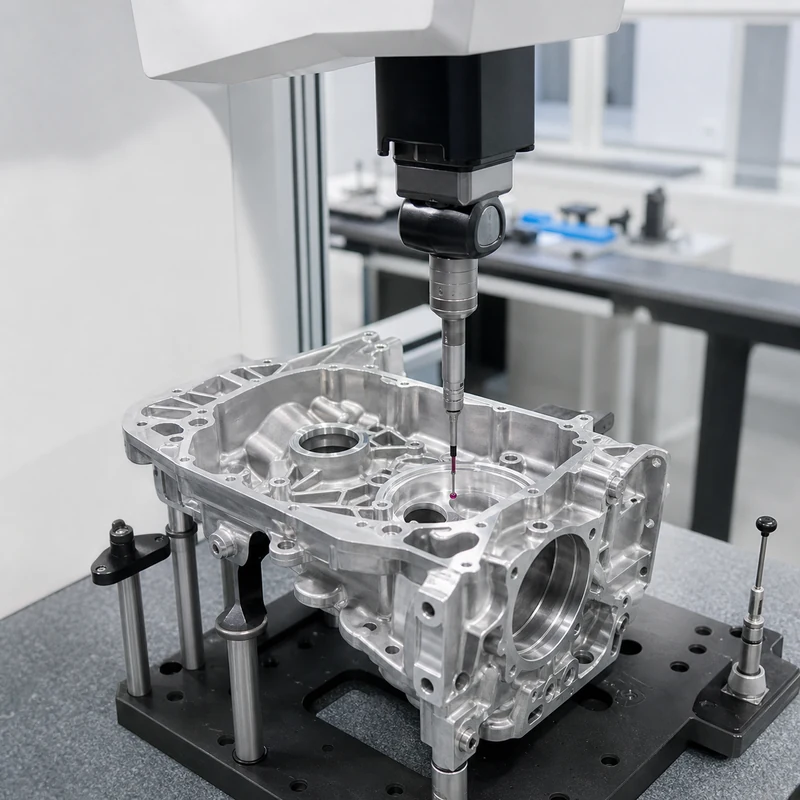
A CMM, or coordinate measuring machine, is an inspection system that measures points on a part using a probe or sensor. The machine records X, Y, and Z coordinates and compares them with the drawing or CAD model. This allows inspectors to verify whether a machined part is within tolerance.

CMM inspection is common for precision CNC parts because many features cannot be judged reliably with calipers alone. Hole patterns, datum relationships, true position, perpendicularity, flatness, and complex profiles need a measurement method that understands the part in 3D space.

What CMM Inspection Can Measure

Feature What CMM checks Why it matters
Hole position Location relative to datums or other holes Controls assembly alignment
Flatness Variation across a surface Important for sealing, mounting, and contact faces
Perpendicularity Angle relationship between axes or surfaces Important for housings, brackets, and fixtures
Profile Deviation from CAD surface or drawing profile Useful for complex milled geometry
True position GD&T-controlled feature location Common for precision hole patterns
Distance and size Lengths, widths, diameters, depths Confirms basic drawing dimensions

How CMM Inspection Works

First, the inspector reviews the drawing and identifies datums, critical features, tolerance zones, and measurement requirements. The part is cleaned and fixtured so it sits in a repeatable position. The CMM then touches or scans selected points. Software compares the measured data with the nominal CAD or drawing values and creates a report.

For repeat production, a CMM program can be saved and reused. This helps measure the same features consistently across batches. For first article inspection, the report may include a broader set of dimensions to validate the initial production process.

CMM Inspection vs Manual Inspection

Inspection method Best for Limitations
Calipers Quick checks of general dimensions Limited for complex geometry and high precision
Micrometers Accurate outside diameters and thickness Feature access and operator method matter
Pin / plug gauges Hole size and fit checks Does not fully describe position or geometry
Thread gauges Internal or external thread fit Does not measure all thread geometry
CMM Datum-based geometry, GD&T, complex parts More time and cost than simple manual checks

When Should Buyers Request CMM Inspection?

  • The part has tight tolerance hole patterns.
  • The drawing uses GD&T such as true position, profile, flatness, or perpendicularity.
  • The part must fit into a larger assembly with little adjustment.
  • The part has multiple machined sides or complex surfaces.
  • The order requires first article inspection or documented quality records.
  • The cost of failure is higher than the cost of measurement.

What Should a CMM Report Include?

A useful CMM report should include part name, drawing number, revision, inspection date, measured features, nominal values, tolerance limits, actual measurements, deviation, pass/fail result, datum reference, and inspector notes. For regulated or high-value projects, material certificate, finish confirmation, and first article documentation may also be needed.

GD&T, Datums, and CMM Inspection

GD&T gives more precise control over how features relate to each other. A hole may pass a simple diameter check but still fail true position if it is not located correctly from the datums. CMM inspection is strong in this situation because it can evaluate the feature within a coordinate system based on the drawing’s datum structure.

If the datum structure is unclear, inspection becomes uncertain. Buyers should make sure the drawing identifies primary, secondary, and tertiary datums where needed. For CNC suppliers, clear datums also help plan workholding and machining sequence.

CMM Inspection for CNC Milling and Turning

For CNC milled parts, CMM inspection is useful for hole patterns, pockets, flatness, profiles, and multi-side relationships. For CNC turned parts, it can support checks for bores, faces, grooves, concentric relationships, cross holes, and secondary milled features. It works best when the drawing clearly separates critical and non-critical dimensions.

How to Reduce Inspection Cost Without Increasing Risk

  • Identify critical dimensions instead of requiring a full report for every feature.
  • Use general tolerance notes for non-critical dimensions.
  • Provide CAD and drawing files together.
  • Define datum structure clearly.
  • Use gauges for simple features and CMM for features that need 3D relationships.
  • Agree on sampling quantity before production.

FAQ

Is CMM inspection required for every CNC part?

No. Many simple parts can be checked with calipers, micrometers, gauges, or visual inspection. CMM is most valuable for precision, complex, or GD&T-controlled parts.

Can CMM inspect threads?

CMM can check thread location and related geometry, but thread fit is usually checked with go/no-go thread gauges.

What is the difference between CMM and FAI?

CMM is a measurement method. First article inspection is a broader process that may include CMM measurements, material checks, finish checks, and documentation.

Does CMM inspection add lead time?

Yes, it can add inspection time, especially for complex reports. But it can reduce risk when parts are expensive or assembly-critical.

What files help CMM inspection?

A 2D drawing with tolerances and datums is essential. A 3D CAD model can help with programming and profile comparison.

Need inspection support for precision parts?

Send your drawing, GD&T notes, CAD file, and critical dimensions. MTSPi can review the right inspection method before quoting.

Contact MTSPi for CNC inspection support

Conclusion

CMM inspection helps confirm that CNC machined parts match the drawing in three-dimensional space. It is most useful for complex geometry, datum-based tolerances, first article inspection, and parts where assembly risk is high.
Categories
Blog Quality & Tolerances

Engineering Tolerances Explained: Meaning, Types, Fits, and Design Use

Engineering tolerance defines how much a manufactured dimension is allowed to vary from the nominal design value. No machining process creates a perfect mathematical part, so tolerances tell the manufacturer what variation is acceptable and what must be rejected.

For CNC parts, good tolerancing is not about making every dimension extremely tight. It is about controlling the features that affect fit, motion, sealing, strength, or alignment while keeping non-critical dimensions practical. This balance improves quality and keeps machining cost under control.

Basic Tolerance Terms

Term Meaning
Nominal dimension The target size shown on the drawing
Upper limit The largest acceptable size
Lower limit The smallest acceptable size
Tolerance zone The total allowed variation between limits
Fit How two mating parts interact after manufacturing
Datum A reference feature used for measurement or assembly

Types of Engineering Tolerances

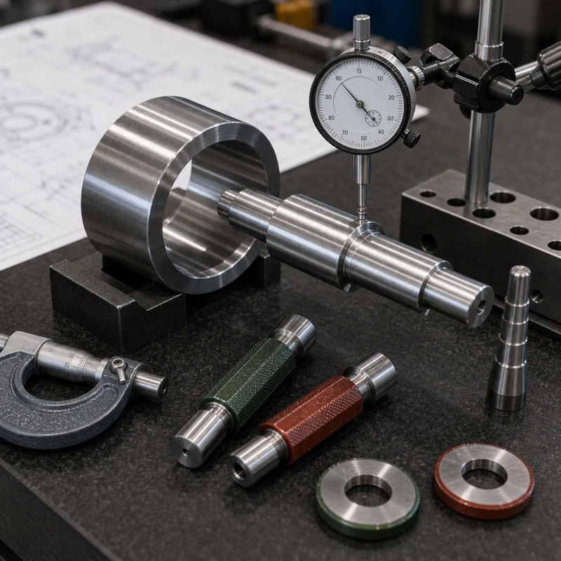
Dimensional tolerances control size, such as length, width, diameter, or depth. Geometric tolerances, often shown through GD&T, control shape, orientation, position, and runout. General tolerances apply when individual dimensions are not specifically called out.

  • Bilateral tolerance allows variation in both directions, such as +/-0.05 mm.
  • Unilateral tolerance allows variation in only one direction, such as +0.02/-0.00 mm.
  • Limit dimensions show the upper and lower values directly.
  • GD&T controls relationships such as flatness, parallelism, profile, true position, and runout.

Fits Between Mating Parts

Fit Type How It Behaves Example
Clearance fit There is always space between mating parts Shaft rotating inside a bushing
Transition fit May have slight clearance or slight interference Accurate locating dowels
Interference fit Parts press together with force Pressed bearing or permanent sleeve

Using ISO 2768 and General Tolerances

Many drawings use a general tolerance standard such as ISO 2768 for dimensions that do not require special control. This keeps drawings readable and avoids unnecessary tight callouts. Critical features should still have specific tolerances or GD&T notes when function demands it.

How to Choose Practical Tolerances

  • Start with the function of the feature, not the machine capability.
  • Tighten only dimensions that affect assembly, motion, sealing, or performance.
  • Consider material movement, heat treatment, plating, anodizing, and other finishing steps.
  • Discuss inspection method for tight or complex tolerances before production.
  • Use datum structures that reflect how the part actually assembles.

If coating thickness matters, coordinate tolerance planning with the surface treatment process. If complex GD&T is involved, confirm that the quality team can measure the feature reliably.

Tolerance and Cost

Tighter tolerance usually increases cost because it may require slower machining, special tooling, more stable fixtures, extra inspection, or secondary finishing. A realistic tolerance strategy helps suppliers quote accurately and reduces back-and-forth during manufacturing review.

Related MTSPi Resources

FAQ

Should every dimension have a tight tolerance?

No. Only functional or assembly-critical features should be tightly controlled.

What is GD&T used for?

GD&T controls geometry and relationships between features, such as position, flatness, parallelism, and runout.

Can surface finishing change tolerances?

Yes. Plating, anodizing, coating, and heat treatment can change dimensions or part behavior, so they should be considered early.

Categories
Blog Quality & Tolerances

CMM Inspection Explained: How Coordinate Measuring Machines Check Parts

CMM inspection uses a coordinate measuring machine to capture accurate points on a part and compare them with a drawing or CAD model. It is one of the most important measurement methods for precision machined components, especially when parts include GD&T callouts, true position, flatness, profile, or complex relationships between features.

For high-value parts, CMM results can support first article inspection, production approval, and ongoing quality control. MTSPi includes CMM and other inspection methods as part of its quality assurance workflow when the drawing requires documented measurement.

How CMM Inspection Works

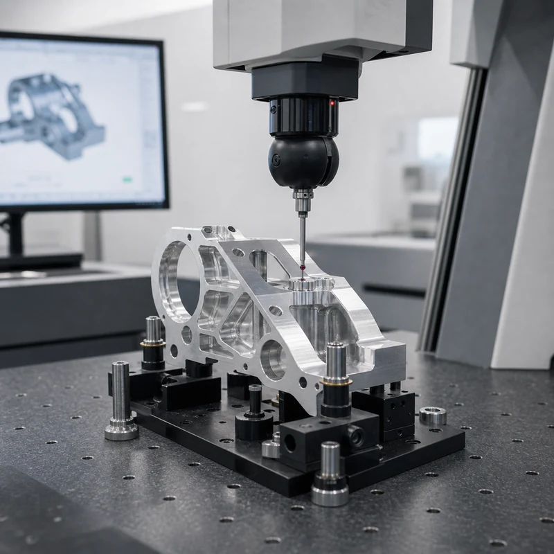
A CMM records coordinates in X, Y, and Z. A probe touches or scans the workpiece, and software uses the measured points to calculate dimensions, feature locations, and geometric tolerances. The part is usually held on a granite table with fixtures that keep it stable during inspection.

  • The operator imports the CAD model or enters drawing dimensions.
  • The part is aligned to a datum structure.
  • The probe measures selected features.
  • Software compares actual data with nominal values and tolerances.
  • A report shows pass/fail results and measured deviations.

Features Commonly Checked by CMM

Feature What CMM Can Confirm
Hole patterns True position, diameter, spacing, and depth references
Flat surfaces Flatness, parallelism, and datum relationships
Profiles and contours Surface profile against CAD geometry
Milled pockets Width, depth, corner location, and wall position
Turned parts Concentricity, runout, diameter, and length relationships

CMM vs Other Inspection Tools

Tool Best For Limitation
Caliper Quick general checks Limited accuracy and operator-dependent
Micrometer Accurate outside or inside dimensions Not ideal for complex feature relationships
CMM GD&T and multi-feature geometry Requires programming and setup time
Optical system Small features and non-contact checks May struggle with hidden surfaces

When to Request a CMM Report

Request CMM inspection when a part has tight tolerances, important assembly alignment, safety-critical function, or customer documentation requirements. If the part includes machining plus coating, it is useful to decide whether inspection should happen before finishing, after finishing, or both. This is especially important for close-fit holes, bearing seats, and sealing surfaces connected to surface treatment.

Related MTSPi Resources

FAQ

Is CMM inspection required for every part?

No. It is most useful for complex geometry, tight tolerance features, GD&T, and documented inspection requirements.

Can a CMM inspect plastic parts?

Yes, but fixturing and probe force should be chosen carefully because plastics may flex.

What is included in a CMM report?

Reports typically include measured dimensions, nominal values, tolerance limits, deviations, and pass/fail status.

Request A Quote

We'll Send You Back with Price Immediately!

DEC 1-31

XMAS SPECEIL

Up to

40% off

CMM Inspection Explained: How Coordinate Measuring Machines Check Parts

We'll Send You Back with Price Immediately!