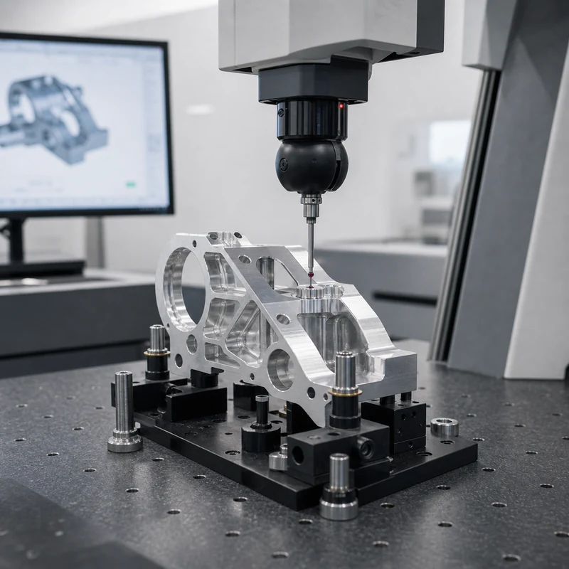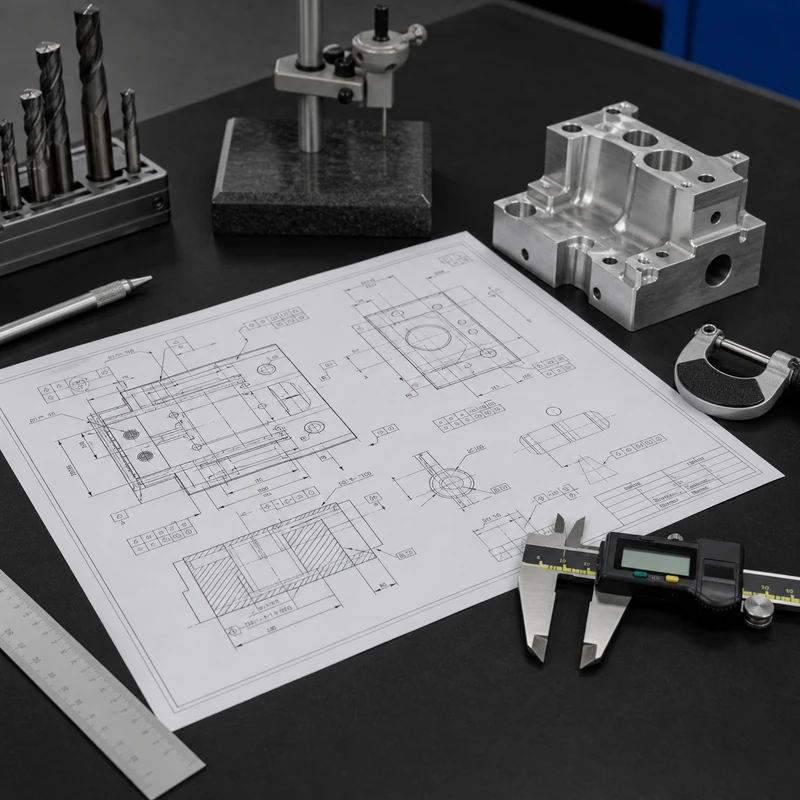
An engineering drawing is more than a picture of a part. For CNC machining, it defines dimensions, tolerances, materials, finishes, threads, inspection requirements, and notes that control how the part should be quoted and produced.
When symbols or abbreviations are missed, the result can be an inaccurate quote, the wrong toolpath, unnecessary rework, or a part that passes size checks but fails assembly. MTSPi reviews CNC machining drawings together with CAD files so unclear requirements are caught before production.
Why Drawing Symbols Matter
A small callout can change the whole manufacturing plan. A simple hole may need drilling only, while a counterbored and tapped hole may need several tools. A general tolerance may be easy to hold, while a tight position tolerance may require a more controlled setup and CMM inspection.
| Drawing information | What it affects | Why it matters in quoting |
|---|---|---|
| Dimension | Feature size and tool selection | Defines the basic material removal plan. |
| Tolerance | Process choice and inspection time | Tight limits can add setup and measurement cost. |
| Surface finish | Tooling, feed, finishing, or polishing | Finish requirements can change cycle time. |
| Hole note | Drilling, boring, tapping, counterboring | Compound hole features need more operations. |
| GD&T | Datum setup and measurement method | Controls relationship between features, not just size. |
Common Dimension and Feature Abbreviations
| Abbreviation or symbol | Meaning | CNC machining note |
|---|---|---|
| DIA | Diameter | Used for holes, shafts, bosses, and circular features. |
| R | Radius | Affects cutter size, corner cleanup, and stress concentration. |
| TOL | Tolerance | Defines acceptable variation from nominal size. |
| REF | Reference | Information only unless the drawing states otherwise. |
| THK | Thickness | Important for plate, sheet, wall, and step features. |
| DP or DEPTH | Depth | Controls blind holes, pockets, slots, and threaded features. |
Hole and Thread Callouts
Hole notes deserve careful review because they often combine several instructions in one short line. Diameter, depth, thread size, thread depth, countersink angle, counterbore diameter, and through-hole condition can all appear together.
| Callout | Meaning | Manufacturing impact |
|---|---|---|
| THRU | The hole passes through the part | Tool must break through the full thickness. |
| TAP | Internal thread required | Needs tapping, thread milling, or forming depending on material. |
| CBORE | Counterbore recess | Adds a flat-bottom recess for a fastener head. |
| CSK | Countersink | Adds an angled recess and angle control. |
| M6 x 1 | Metric thread size and pitch | Requires matching thread tool and inspection gauge. |
Fastener features also affect assembly and cost. If a part has many tapped holes, deep threads, or difficult counterbores, review them early with reduce CNC machining cost and the intended assembly method.
Surface Finish and Inspection Notes
Surface finish symbols and roughness values control how smooth a surface must be. A cosmetic face, sealing face, sliding surface, and hidden clearance pocket should not automatically receive the same finish requirement.
| Requirement | What to clarify | Inspection method |
|---|---|---|
| Ra value | Which surfaces need the value | Roughness tester or agreed visual standard |
| No burrs | Edges affected and acceptable break size | Visual check, magnification, or edge standard |
| Critical dimension | Sampling plan and report format | Caliper, micrometer, pin gauge, CMM, or fixture |
| Flatness or parallelism | Datum and measurement area | CMM, surface plate, height gauge, or fixture |
For parts with tight tolerances, ask how the supplier will measure the feature before machining starts. MTSPi connects the drawing to CNC machining quality inspection so the inspection plan matches the acceptance requirement.
GD&T Symbols in CNC Projects
Geometric Dimensioning and Tolerancing controls the shape, orientation, and location of features relative to datums. It is especially important when parts must assemble with other components or when hole patterns, flat surfaces, and mating features need controlled relationships.
| GD&T concept | Plain-English meaning | CNC planning issue |
|---|---|---|
| Datum | Reference feature used for measurement | Fixture and inspection setup must match the drawing intent. |
| Position | Allowed location error of a feature | Hole patterns may need controlled setup and CMM reporting. |
| Flatness | How much a surface may vary from flat | Thin parts may need stress and clamping control. |
| Parallelism | How closely one feature aligns with another | Setup sequence and datum handling matter. |
| Runout | Circular variation during rotation | Turning process and chucking method are important. |
File Package Checklist for an RFQ
- 3D CAD file for geometry, preferably STEP or another neutral format.
- PDF drawing with tolerances, material, finish, threads, and notes.
- Quantity, target lead time, and whether prototypes or production batches are needed.
- Critical features that affect assembly, sealing, motion, or appearance.
- Inspection report, material certificate, or finish documentation requirements.
Clear drawing data helps the supplier choose between CNC milling service, CNC turning service, finishing, and inspection options without guessing.
Conclusion
Engineering drawing symbols and abbreviations turn design intent into manufacturing instructions. For CNC machining, the most important items are dimensions, tolerances, hole notes, surface finish, GD&T, material, and inspection requirements. A careful drawing review before quoting saves time, reduces ambiguity, and gives both buyer and supplier a clearer path to acceptable parts.