Categories
Blog CNC Materials Design, Cost & Sourcing

Properties of Mild Steel: CNC Machining Material Guide

Mild steel is one of the most widely used metals in manufacturing because it offers a practical balance of strength, cost, machinability, weldability, and availability. For CNC machined parts, it is often selected when the design needs a tough and economical steel component but does not require the corrosion resistance of stainless steel or the low weight of aluminum.

This guide explains the properties of mild steel from a custom-part perspective: what it is, how it behaves during CNC machining, when to choose it, when to avoid it, and which finishes can protect it. If you are comparing steel, aluminum, stainless steel, brass, copper, titanium, or engineering plastics, MTSPi’s CNC machining materials section can help you narrow the choice.

What Is Mild Steel?

Mild steel is a low-carbon steel. It normally contains a relatively small amount of carbon compared with medium-carbon or high-carbon steel, which makes it easier to form, weld, cut, drill, mill, turn, and fabricate. The low carbon level also makes mild steel less brittle and more forgiving in many general-purpose mechanical applications.

Because mild steel is economical and widely available in plate, bar, rod, tube, sheet, and structural forms, it is used across machinery, automation, tooling, automotive components, construction hardware, fixtures, frames, brackets, and equipment parts.

Key Properties of Mild Steel

Property Typical Behaviour Why It Matters for CNC Parts
Strength Moderate strength for general mechanical use Suitable for brackets, fixtures, plates, spacers, shafts, and frames
Ductility Can deform before fracture Useful when parts need toughness instead of brittle failure
Machinability Generally practical to mill, drill, tap, and turn Good for custom CNC parts when tools, feeds, and coolant are controlled
Weldability Usually easier to weld than higher-carbon steels Good for machined-and-welded assemblies
Formability Can be bent and formed in many sheet or plate applications Useful for combined machining and fabrication projects
Corrosion resistance Low compared with stainless steel Often needs coating, plating, oil, paint, or black oxide
Cost Usually lower than stainless steel, titanium, and many specialty alloys Good choice for cost-sensitive parts

Mild Steel vs Carbon Steel

Mild steel is part of the broader carbon steel family. Carbon steel includes low-carbon, medium-carbon, and high-carbon grades. Mild steel usually refers to the low-carbon end of that range. As carbon content increases, steel can become stronger and harder, but it may also become less ductile, less weldable, and more demanding to machine or heat treat.

For many CNC projects, the exact grade matters more than the general name. A drawing should specify the material grade, standard, heat treatment condition, and finish requirements when mechanical performance is important.

Mild Steel vs Stainless Steel

Comparison Point Mild Steel Stainless Steel
Corrosion resistance Rusts easily without protection Much better corrosion resistance depending on grade
Cost Usually more economical Typically higher material and machining cost
Machinability Often easier and faster to machine Can work harden and may require slower machining
Appearance Needs coating or finishing for long-term clean appearance Can remain bright or passivated in many environments
Best use General mechanical, structural, fixture, and cost-sensitive parts Corrosive, hygienic, marine, medical, or food-related environments

If corrosion resistance is a key requirement, stainless steel CNC machining may be a better fit. If the part will be painted, plated, powder coated, or used indoors, mild steel may offer better value.

Mild Steel vs Aluminum

Aluminum is lighter and naturally more corrosion resistant than mild steel, while mild steel is usually stronger, stiffer, and more economical for many load-bearing components. Aluminum often wins when weight, speed of machining, heat dissipation, or anodized appearance matter. Mild steel often wins when cost, stiffness, weldability, and general mechanical robustness matter. See aluminum CNC machining for comparison context.

Is Mild Steel Good for CNC Machining?

Yes. Mild steel is a common CNC machining material for both prototypes and production parts. It can be milled, turned, drilled, tapped, bored, reamed, and surface finished. It is especially useful for parts that need practical strength, threaded holes, flat plates, shafts, brackets, spacers, machine fixtures, and weldable assemblies.

  • CNC milling: suitable for plates, brackets, fixture blocks, mounting features, slots, and pockets.
  • CNC turning: suitable for shafts, pins, bushings, collars, threaded parts, and round spacers.
  • Drilling and tapping: practical for mounting holes and threaded interfaces.
  • Grinding or finishing: useful when better flatness, surface finish, or fit is required.

For part geometry that uses pockets, precision holes, or mating surfaces, CNC milling can provide accurate features. For round parts, pins, shafts, and threaded components, CNC turning may be more efficient.

Advantages of Mild Steel

  • Lower material cost compared with many stainless steels, titanium alloys, and specialty metals.
  • Good availability in many stock forms and thicknesses.
  • Useful strength and stiffness for general engineering parts.
  • Good weldability for fabricated assemblies.
  • Predictable machining behaviour for many common grades.
  • Compatible with many protective finishes.

Limitations of Mild Steel

  • Rusts quickly if exposed to moisture without protection.
  • Heavier than aluminum and many engineering plastics.
  • Not ideal for sanitary, marine, chemical, or outdoor environments unless coated properly.
  • Not as strong or wear-resistant as heat-treated alloy steels.
  • Can require deburring, edge protection, and post-processing to meet cosmetic expectations.

Common Grades and Similar Materials

Grade names vary by region and standard, so sourcing teams should confirm the exact specification on the drawing or purchase order. Common mild steel or low-carbon steel choices may include grades used for general fabrication, machining, plate work, or structural applications. Equivalent grades are not always identical across standards, so final selection should be verified against mechanical and chemical requirements.

Material Type Typical Use Selection Note
Low-carbon steel bar Turned shafts, pins, spacers, collars Good for economical machined round parts
Mild steel plate Brackets, fixture plates, mounting bases Check flatness, thickness tolerance, and surface condition
Cold rolled steel Parts needing better surface finish and tighter stock tolerance Often cleaner for precision plates and small components
Hot rolled steel Frames, large plates, structural parts Scale and surface condition may require machining or blasting
Free-machining steel High-volume turned parts Improves machinability but may affect weldability or compliance requirements

Surface Treatment for Mild Steel

Because mild steel rusts, finishing is often part of the design decision. A part used indoors may only need oil, black oxide, or paint. A visible product part may need powder coating or plating. A part exposed to moisture may need zinc plating, nickel plating, e-coating, or a more corrosion-resistant base material. MTSPi’s surface treatment section covers common finishing options for CNC parts.

Finish What It Does Typical Mild Steel Use
Black oxide Adds a dark appearance and light corrosion resistance with oil Tooling, fixtures, machine parts
Zinc plating Improves corrosion resistance at low cost Fasteners, brackets, hardware
Nickel plating Improves wear, appearance, and corrosion resistance Precision parts, shafts, decorative or functional surfaces
Powder coating Durable colored protective coating Frames, covers, brackets, equipment panels
Painting Economical corrosion and appearance protection Large fabricated or structural parts

Design Tips for CNC Machined Mild Steel Parts

  • Specify the exact grade and standard when strength or compliance matters.
  • Add realistic radii to internal corners to reduce stress concentration and machining cost.
  • Avoid unnecessary tight tolerances on non-critical faces.
  • Call out threaded holes, reamed holes, bearing fits, and datum surfaces clearly.
  • Plan coating thickness if the part has mating surfaces, sliding fits, or threads.
  • Use stainless steel or plating when corrosion is a serious risk.
  • Review welding sequence and post-weld machining needs for assemblies.

Typical Applications

Mild steel is often selected where the part needs strength, stiffness, weldability, and affordability more than light weight or corrosion resistance. It appears in machine bases, tooling plates, brackets, frames, fixture components, pins, collars, shafts, mounting hardware, guards, covers, and general industrial parts.

Industries such as automation, machinery, automotive equipment, robotics fixtures, and industrial hardware often use mild steel when a practical and economical metal is needed. For application-specific support, see MTSPi’s CNC machining applications.

When Should You Avoid Mild Steel?

Mild steel may not be the best option for parts that operate outdoors, in salt spray, in chemical exposure, in medical environments, in food-contact areas, or where low weight is essential. It may also be unsuitable when the part requires very high strength, high hardness, high fatigue resistance, or excellent corrosion resistance without coating.

In those cases, consider stainless steel, aluminum, alloy steel, titanium, brass, copper, or engineering plastics depending on the functional requirement.

How MTSPi Supports Mild Steel CNC Machining

MTSPi can machine mild steel parts from drawings and 3D models for prototypes, low-volume production, fixtures, brackets, shafts, plates, and mechanical components. We can review part geometry, tolerance, surface finish, coating needs, and inspection requirements before production.

To request a quote, send your CAD file, 2D drawing, quantity, steel grade preference, finish requirement, and application notes through the contact page. If you are unsure whether mild steel, stainless steel, or aluminum is better, include the operating environment and load requirements so the material choice can be reviewed.

FAQ

What is mild steel made of?

Mild steel is mainly iron with a low amount of carbon, plus small amounts of other elements depending on the grade and standard.

Does mild steel rust?

Yes. Mild steel can rust when exposed to moisture or corrosive environments, so protective finishing is often required.

Is mild steel easy to machine?

Many mild steel grades are practical to CNC machine. Tooling, coolant, feeds, speeds, chip control, and grade selection still matter for finish and dimensional stability.

Is mild steel stronger than aluminum?

Mild steel is usually stronger and stiffer than common aluminum alloys, but aluminum is much lighter and often easier to machine quickly.

Can mild steel be used for precision parts?

Yes, mild steel can be used for precision components when the grade, stock condition, machining process, tolerances, and finishing are specified correctly.

Can MTSPi machine mild steel prototypes and production parts?

Yes. MTSPi supports CNC machined mild steel prototypes, fixtures, brackets, shafts, plates, and low-volume production parts.

Categories
Blog CNC Materials Quality & Tolerances

Understanding Yield Strength: A Practical Guide for CNC Machined Parts

Yield strength is one of the most useful material properties for engineers who design custom CNC machined parts. It tells you how much stress a material can take before it stops behaving elastically and starts to deform permanently. In practical terms, it helps answer a direct question: will this bracket, shaft, housing, fixture, or plastic component keep its shape under real load?

This guide explains yield strength in plain engineering language, then connects it to CNC material selection, part geometry, safety factors, machining process choices, and inspection planning. If you are choosing between aluminum, stainless steel, brass, copper, titanium, Delrin, nylon, or PEEK, MTSPi’s CNC machining materials library and custom CNC machining services can help review the application before production.

What Is Yield Strength?

Yield strength is the stress at which a material begins to change shape permanently. Before this point, the material is in the elastic region: it can stretch, bend, or compress slightly and then return to its original shape when the load is removed. After the yield point, plastic deformation begins. The part may still be intact, but it no longer returns fully to its original dimensions.

For a CNC machined component, that distinction matters. A part does not need to break to fail. A bent mounting bracket, an ovalized bore, a stretched fastener area, or a shaft with permanent deflection can cause assembly problems even if the material has not fractured.

Yield Strength vs Tensile Strength

Property What It Means Why It Matters in CNC Part Design
Yield strength Stress where permanent deformation begins Used to prevent bending, stretching, or dimensional loss under working load
Ultimate tensile strength Maximum stress before fracture during tensile loading Useful for understanding final failure capacity
Elastic modulus Material stiffness in the elastic region Controls deflection before yield
Elongation How much the material can stretch before breaking Helps evaluate ductility and toughness
Hardness Resistance to indentation or surface wear Useful for wear surfaces, tooling contact, and finish expectations

A material can have high tensile strength but still yield earlier than expected under design loads. For many structural CNC parts, yield strength is often more important than ultimate strength because the part must maintain alignment, flatness, clearance, and function.

Stress, Strain, and the Yield Point

Stress is the force applied over an area. Strain is the amount of deformation that results from that stress. During a tensile test, a sample is pulled until it stretches and eventually breaks. The stress-strain curve shows how the material behaves from elastic deformation through yielding and final fracture.

Many metals have a visible transition from elastic to plastic behavior. Some materials do not show a sharp yield point, so engineers use an offset yield strength, commonly based on a defined amount of permanent strain. This creates a consistent way to compare materials even when the curve is gradual.

Why Yield Strength Matters for CNC Machined Parts

  • It helps prevent permanent bending in brackets, plates, arms, and frames.
  • It supports shaft, pin, and fastener-area sizing under mechanical load.
  • It helps engineers choose between aluminum, steel, stainless steel, titanium, and engineering plastics.
  • It affects whether a part can survive clamping, press fits, assembly forces, and service loads.
  • It informs safety factors when parts are used in machinery, automation, robotics, aerospace, or medical equipment.

For example, a lightweight aluminum prototype may be suitable for a visual housing, while a loaded fixture plate may need a stronger aluminum alloy, stainless steel, or a design with thicker ribs. A turned shaft may need both yield strength and surface hardness, which makes CNC turning, material grade, heat treatment, and finishing all part of the same decision.

How Yield Strength Is Tested

Yield strength is usually measured with a tensile test. A standardized specimen is clamped in a testing machine and pulled at a controlled rate. The machine records force and elongation, which are converted into stress and strain. The resulting curve shows elastic behavior, yield, strain hardening, and eventual fracture.

For sourced CNC parts, the machine shop normally does not test every machined part for yield strength. Instead, the value usually comes from material standards, mill certificates, supplier data sheets, or customer-specified requirements. Critical projects may require material certificates, hardness checks, dimensional inspection, or additional validation testing.

Typical Yield Strength Ranges for Common CNC Materials

The table below gives general comparison ranges only. Actual values depend on alloy, temper, heat treatment, manufacturing route, supplier, standard, and test condition. Always confirm the exact grade and certification requirements for critical applications.

Material Family Typical Yield Strength Direction Common CNC Applications
Aluminum alloys Medium; varies widely by grade and temper Housings, brackets, heat sinks, aerospace-style lightweight parts
Stainless steel Medium to high depending on grade and condition Corrosion-resistant shafts, fittings, medical and food-equipment components
Carbon and alloy steel Medium to very high depending on heat treatment Pins, shafts, tooling components, structural machine parts
Titanium alloys High strength-to-weight ratio Aerospace, medical, high-performance lightweight parts
Brass and copper alloys Lower to medium depending on alloy Connectors, fittings, electrical and thermal components
Engineering plastics Lower than metals; highly dependent on polymer and reinforcement Insulators, wear parts, lightweight fixtures, housings

Material Selection Examples

Aluminum CNC Machining

Aluminum is often selected for CNC prototypes and production parts because it machines quickly, has a useful strength-to-weight ratio, and accepts finishes such as anodizing. For loaded parts, yield strength depends heavily on alloy and temper. A cosmetic aluminum cover and a structural automation bracket may need different grades. See aluminum CNC machining for related material and process context.

Stainless Steel CNC Machining

Stainless steel combines corrosion resistance with good mechanical strength. It is used for shafts, fittings, valve parts, medical components, marine parts, and food-equipment hardware. Yield strength, machinability, corrosion resistance, and cost vary by grade, so material choice should match the working environment. See stainless steel CNC machining.

Titanium CNC Machining

Titanium alloys offer strong yield performance for their weight, plus excellent corrosion resistance. They are valuable for aerospace, medical, and high-performance applications, but they require careful machining strategy, tooling, heat control, and inspection planning. See titanium CNC machining.

Engineering Plastics

Plastics such as ABS, Delrin, nylon, and PEEK have much lower yield strength than metals, but they can be ideal when the design needs low weight, insulation, wear resistance, chemical resistance, or lower friction. For plastic parts, creep, temperature, moisture absorption, and wall thickness are often as important as short-term yield data. See CNC plastic machining.

Yield Strength and Part Geometry

A material property alone does not make a part strong. Geometry controls how stress moves through the component. Sharp inside corners, thin sections, small radii, undercut areas, and holes near loaded edges can concentrate stress and cause local yielding. A stronger material may still fail if the design creates a severe stress concentration.

  • Use fillets around internal corners and shoulder transitions.
  • Increase wall thickness or add ribs where deflection is a concern.
  • Avoid placing holes too close to highly loaded edges.
  • Match thread engagement length to the material and load.
  • Consider load direction when choosing grain direction, stock form, and machining setup.
  • Use finite element analysis or prototype testing for high-risk structural parts.

Yield Strength in Prototypes vs Production Parts

A prototype should use a material that answers the right engineering question. If the prototype is only for fit and appearance, a substitute material may be acceptable. If the prototype must carry load, validate threads, prove fatigue behavior, or represent final product performance, material grade and yield strength must be closer to the production condition. This is one reason CNC machining is valuable in rapid prototyping.

Production adds another layer: repeatability. The first prototype may pass because it was machined carefully from a known stock piece. Batch production needs consistent material supply, documented grade, controlled heat treatment, finish control, and inspection criteria.

How Manufacturing Processes Affect Yield Strength

Yield strength can change with alloy composition, heat treatment, cold working, casting condition, forging, additive manufacturing, and post-processing. CNC machining usually removes material and shapes the part; it does not automatically improve the base material strength. However, machining strategy can influence residual stress, surface condition, notch sensitivity, and dimensional stability.

Process or Condition Possible Effect Design Note
Heat treatment Can significantly raise or change yield strength Specify grade and condition clearly on drawings
Cold working May increase strength but reduce ductility Confirm supplier data and forming history
Casting Properties may vary with porosity and microstructure Critical surfaces may need machining and inspection
Additive manufacturing Properties can vary by orientation and post-processing Do not assume printed strength equals wrought material
CNC machining Usually preserves base material strength but changes geometry and surface condition Avoid stress risers and manage thin-wall distortion

Safety Factor and Real-World Loads

Engineers rarely design a part to operate exactly at yield strength. They use a safety factor to account for uncertainty in loads, material variation, surface condition, temperature, shock, vibration, fatigue, corrosion, and assembly effects. The required safety factor depends on the application and risk level.

For non-critical fixtures, a modest factor may be acceptable. For lifting equipment, aerospace components, medical devices, or safety-critical assemblies, the design standard, documentation, and testing requirements are much stricter. A CNC supplier can support manufacturability and inspection, but the final safety requirement should come from the product design team or applicable standard.

Common Mistakes When Using Yield Strength

  • Choosing material only by yield strength while ignoring stiffness, toughness, corrosion, wear, or machinability.
  • Using generic online values instead of the exact alloy, grade, temper, and standard.
  • Forgetting that heat treatment and supplier condition can change properties.
  • Assuming a prototype made from one material will perform like the production material.
  • Ignoring permanent deformation in holes, thin walls, press fits, and threaded features.
  • Treating plastics like metals without considering creep, temperature, and moisture.

How MTSPi Helps With Material and Strength Decisions

MTSPi supports CNC machining for metal and plastic parts where material choice, geometry, tolerance, and finishing must work together. We can review drawings for material feasibility, machining access, stress-sensitive features, wall thickness, thread design, surface finish, and inspection requirements before production.

For a strength-sensitive part, send the 3D model, 2D drawing, expected load direction, quantity, material preference, finish, and inspection requirements through our contact page. If the material is not fixed, we can help compare options across the CNC metal machining and plastic material families.

FAQ

What is yield strength in simple terms?

Yield strength is the point where a material begins to bend, stretch, or deform permanently instead of springing back to its original shape.

Is yield strength the same as tensile strength?

No. Yield strength marks the start of permanent deformation. Tensile strength is the maximum stress a material can withstand before breaking in a tensile test.

Why does yield strength matter for CNC machined parts?

It helps prevent brackets, shafts, housings, fixtures, and threaded areas from permanently deforming under load, clamping, assembly, or service conditions.

Which CNC metal has the highest yield strength?

High-strength alloy steels and some titanium alloys can have very high yield strength, but the best choice depends on weight, corrosion resistance, machinability, heat treatment, cost, and application requirements.

Do plastics have yield strength?

Yes, many plastics have yield data, but plastic behavior is also affected by creep, temperature, moisture, reinforcement, wall thickness, and long-term loading.

Can MTSPi help choose a material based on yield strength?

Yes. MTSPi can review the application, drawing, tolerance, and service conditions to help compare CNC material options before quoting or production.

Categories
Blog CNC Materials

Rare Earth Metals: Properties, Uses, and Manufacturing Design Guide

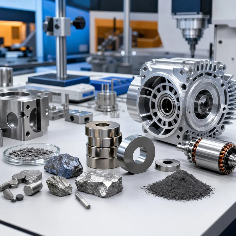
Rare earth metals are a family of 17 elements valued less for ordinary strength and more for magnetic, optical, electrical, catalytic, and high-temperature behavior. They are important in motors, sensors, displays, medical equipment, aerospace systems, renewable energy hardware, robotics, and precision electronics.

For manufacturing teams, rare earth metals are usually not selected like aluminum, steel, or titanium. They are most often used inside magnets, coatings, alloys, ceramics, polishing compounds, catalysts, and electronic materials. The surrounding housings, brackets, shafts, heat sinks, fixtures, and assembly parts still rely on conventional CNC materials. This guide explains the practical role of rare earth materials and how to think about them during custom CNC machining and product development.

What Are Rare Earth Metals?

Rare earth metals include the 15 lanthanide elements plus scandium and yttrium. The name can be confusing because many of these elements are not extremely scarce in the earth’s crust. They are called rare because they are commonly dispersed, mixed with other minerals, and difficult to separate into high-purity usable materials.

Group Elements
Lanthanides Lanthanum, cerium, praseodymium, neodymium, promethium, samarium, europium, gadolinium, terbium, dysprosium, holmium, erbium, thulium, ytterbium, lutetium
Related rare earth elements Scandium and yttrium

Why Rare Earth Metals Matter in Manufacturing

Rare earth materials solve problems that common structural metals cannot solve alone. Neodymium and dysprosium help create compact high-strength permanent magnets. Europium and terbium support display and lighting phosphors. Cerium is used in polishing and catalysts. Yttrium appears in ceramics, lasers, and high-performance materials. Scandium can improve certain aluminum alloys.

This does not mean rare earth metals replace structural metals. A motor may use rare earth magnets, but its housing may still be machined from aluminum. A sensor may depend on rare earth functional materials, while the enclosure may use stainless steel, brass, plastic, or titanium.

Common Rare Earth Metals and Uses

Element Symbol Manufacturing Relevance
Neodymium Nd Strong permanent magnets for motors, robotics, sensors, and compact assemblies
Dysprosium Dy Improves high-temperature magnet performance in demanding systems
Terbium Tb Phosphors, magnetostrictive materials, electronics, and specialty devices
Samarium Sm Samarium-cobalt magnets for high-temperature and harsh environments
Cerium Ce Polishing compounds, catalysts, glass additives, and alloy uses
Lanthanum La Batteries, optical glass, catalysts, and specialty alloys
Yttrium Y Ceramics, lasers, phosphors, thermal barrier materials, and electronics
Scandium Sc Aluminum alloy modification for lightweight high-performance components

Key Properties

Magnetic performance

The best-known rare earth application is permanent magnets. Neodymium-based magnets provide very high magnetic strength in a small package. Samarium-cobalt magnets are useful where heat resistance and corrosion behavior matter. These magnets appear in electric motors, actuators, speakers, sensors, holding fixtures, and compact motion-control systems.

Optical and luminescent behavior

Some rare earth elements emit specific colors or interact with light in useful ways. This makes them important in displays, LED lighting, lasers, fiber optics, medical imaging, inspection instruments, and optical glass.

Electrical and electronic function

Rare earth materials can influence magnetic fields, electronic behavior, and signal performance. They are not usually used as basic conductors like copper, but they help electronic systems achieve functions that standard metals cannot provide by themselves.

Temperature and stability advantages

Certain rare earth additions improve performance at elevated temperature. This is especially important for motors, aerospace hardware, energy systems, and industrial machinery where heat can reduce magnetic strength or dimensional stability.

Light Rare Earths vs Heavy Rare Earths

Rare earth elements are often grouped into light rare earth elements and heavy rare earth elements. Light rare earths generally have lower atomic numbers and are more abundant. Heavy rare earths are often less available and can be more strategically sensitive because they are important for high-performance magnets and specialized technologies.

Category Typical Elements Practical Note
Light rare earth elements Lanthanum, cerium, praseodymium, neodymium, samarium Often used in magnets, catalysts, glass, polishing, batteries, and alloys
Heavy rare earth elements Europium, gadolinium, terbium, dysprosium, yttrium, lutetium and related elements Important for high-temperature magnets, phosphors, lasers, ceramics, and advanced electronics

Rare Earth Metals vs Common CNC Metals

In CNC machining, material selection usually starts with strength, weight, corrosion resistance, machinability, thermal behavior, surface finish, and cost. Rare earth metals are different. They are selected for functional behavior inside a system rather than for ordinary load-bearing structure.

Material Family Main Role Typical CNC Relevance
Rare earth materials Magnetic, optical, catalytic, electronic, and high-temperature functions Usually used as magnets, additives, ceramics, coatings, or specialty components
Aluminum Lightweight structures, housings, heat sinks, brackets, prototypes Excellent machinability and weight reduction
Stainless steel Corrosion-resistant structural and mechanical parts Good for medical, food, marine, and industrial components
Titanium High strength-to-weight ratio and corrosion resistance Useful for aerospace, medical, and high-performance parts
Copper and brass Electrical, thermal, fittings, bushings, connectors Strong conductivity and good machinability depending on grade

Design Notes for Parts That Use Rare Earth Magnets

Many CNC machined parts interact with rare earth magnets even if the rare earth material itself is not machined as the main component. Examples include motor housings, sensor mounts, magnetic couplings, robotics grippers, test fixtures, encoder parts, and compact electromechanical assemblies.

  • Allow realistic pocket clearance for magnet installation and adhesive thickness.
  • Consider magnet orientation and assembly sequence before finalizing the housing design.
  • Protect brittle magnets from impact, edge loading, and press-fit stress.
  • Account for heat exposure because magnet strength can drop if the grade is not suitable.
  • Use coatings or encapsulation when corrosion or fluid exposure is possible.
  • Define inspection points for critical magnet seats, alignment features, and mating surfaces.

Material Selection for Advanced Assemblies

Rare earth materials often work best as part of a broader material system. A compact motor may combine rare earth magnets, copper windings, machined aluminum housing, stainless fasteners, and engineered plastic insulation. A sensor assembly may combine magnetic material with a machined bracket, sealed enclosure, and precision-located reference surfaces. MTSPi can review these surrounding CNC components through our materials library, surface treatment planning, and quality assurance workflow.

Quality and Inspection Considerations

For rare-earth-related assemblies, inspection should focus on the features that control fit, alignment, thermal path, and reliability. The machined part may need tight flatness, bore position, pocket depth, thread quality, or surface finish even when the functional rare earth element is purchased separately.

  • Check magnet pockets, bores, datum surfaces, and locating shoulders against the drawing.
  • Confirm surface finish where adhesives, seals, bearings, or magnetic components contact the part.
  • Plan coating thickness so plated or anodized surfaces do not close up critical fits.
  • Use documented inspection when the part supports motors, sensors, aerospace equipment, or medical devices.

How MTSPi Supports Manufacturing Projects

MTSPi does not treat rare earth metals as a generic substitute for normal CNC materials. Instead, we help engineers choose the right machined support parts around the functional material. Send the 3D model, 2D drawing, material preference, magnet or electronic component requirements, quantity, surface finish, and inspection expectations through our contact page. We can then review material options, machining strategy, tolerance risk, finishing, and assembly-critical features.

Related MTSPi Resources

FAQ

Are rare earth metals actually rare?

Not always. Many are reasonably abundant in the earth’s crust, but they are difficult to mine, separate, refine, and supply in high-purity forms.

Are rare earth metals stronger than steel?

No. Their main value is functional performance such as magnetism, optical behavior, and electronic properties. Steel, aluminum, titanium, and other engineering metals are usually better for structural CNC parts.

Which rare earth element is used in strong magnets?

Neodymium is widely used in strong permanent magnets. Dysprosium or terbium may be added for higher-temperature performance, while samarium-cobalt magnets are used in some harsh environments.

Can rare earth metals be CNC machined?

Some rare earth materials can be processed, but they are not common everyday CNC stock materials. In most projects, CNC machining is used for the surrounding housings, brackets, fixtures, and precision parts that hold or protect rare earth components.

What industries use rare earth materials?

Electric vehicles, robotics, aerospace, medical devices, renewable energy, electronics, sensors, lighting, displays, and industrial automation all use rare earth materials in different ways.

Categories
Blog CNC Materials

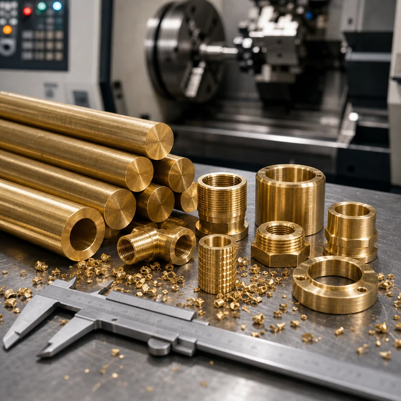
Brass Grades for CNC Machining: Selection Guide for Custom Parts

Brass is a copper-zinc alloy family known for excellent machinability, attractive appearance, corrosion resistance, and good electrical performance. Different brass grades behave differently during cutting, threading, forming, and finishing.

For CNC parts, brass is often selected for fittings, bushings, inserts, connectors, valves, decorative hardware, and electrical components.

Quick Guide to Brass Grades For Cnc Machining

Item Purpose Manufacturing Note
C360 Free-cutting brass Excellent machinability for turned parts
C260 Cartridge brass Good formability and corrosion resistance
C464 Naval brass Better marine corrosion resistance
Lead-free brass Applications with regulatory or environmental requirements Machinability varies by alloy

Material Selection Notes

Material choice affects machinability, tool wear, achievable tolerance, corrosion resistance, surface finish, and long-term part performance. Always connect material grade to the real application.

  • Match the process to the material and geometry.
  • Confirm critical dimensions before quoting.
  • Plan finishing and inspection before production.
  • Use prototypes to validate fit when the assembly risk is high.

Common Applications

Brass Grades For Cnc Machining is relevant for prototypes, custom components, fixtures, low-volume manufacturing, maintenance parts, and engineering projects where function, cost, and lead time must be balanced.

Cost Factors

Cost usually depends on setup time, material price, number of operations, tool access, tolerance requirements, surface finish, inspection depth, and batch quantity.

Design and Sourcing Notes

The safest design approach is to define the part’s function first, then assign tolerances only where they affect assembly, movement, sealing, safety, or long-term performance.

  • Avoid unnecessary tight tolerances on non-critical surfaces.
  • Keep internal corners, hole depths, wall thickness, and tool access realistic.
  • Call out cosmetic surfaces separately from functional surfaces.
  • Include material, finish, quantity, and inspection notes in the RFQ package.

Quality Checks That Matter

Quality control may include visual inspection, dimensional measurement, thread checks, gauge checks, flatness checks, runout checks, surface finish checks, or CMM inspection depending on the part’s risk and function.

Related MTSPi Resources

FAQ

What is the main consideration for brass grades for CNC machining?

The main consideration is whether the design, material, and process can meet the functional requirements without adding unnecessary cost or risk.

Can MTSPi help with custom parts for this topic?

Yes. MTSPi can review drawings, material requirements, tolerances, finishing, and inspection needs for custom CNC machined or related manufacturing parts.

What should I send for a quote?

Send 3D CAD, 2D drawings, material grade, quantity, surface finish requirements, tolerance notes, and any critical assembly information.

Categories
Blog CNC Materials

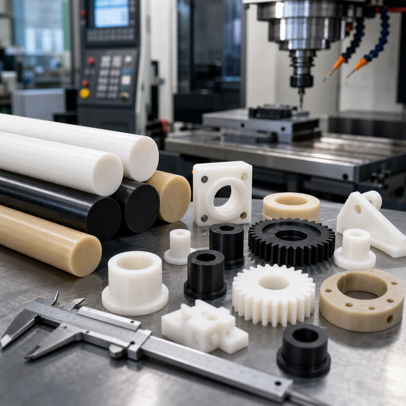
Types of Nylon: Grades, Properties, and CNC Machining Selection Guide

Nylon is one of the most widely used engineering plastics, but the word “nylon” does not describe one single material. PA6, PA66, PA12, PA11, PA6/12, glass-filled nylon, mineral-filled nylon, and impact-modified nylon can behave very differently in machining, assembly, moisture exposure, heat, and long-term wear. Choosing the wrong type can lead to swelling, loose tolerances, tool wear, cracked thin walls, or parts that work in the prototype stage but fail in production.

This guide explains the main types of nylon from a CNC machining and product-design point of view. It is written for engineers, sourcing teams, and product developers who need practical material selection help before ordering machined plastic parts. For project-specific material review, MTSPi can also evaluate drawings through our nylon CNC machining and broader CNC plastic machining capabilities.

Quick Answer: Which Type of Nylon Should You Choose?

Nylon Type Best For Main Strength Main Caution
PA6 / Nylon 6 General machined parts, gears, rollers, wear pads, prototypes Tough, economical, good wear resistance Absorbs moisture and may move dimensionally
PA66 / Nylon 6/6 Higher strength parts, wear components, electrical and mechanical parts Higher stiffness, wear resistance, and heat performance than PA6 Still absorbs moisture; can be harder to machine cleanly
PA6/12 Moisture-sensitive applications, molded parts, cable and fluid-system components Lower moisture absorption than PA6 or PA66 Usually less strong than PA66
PA11 Flexible, impact-resistant, lower-moisture parts, often 3D printed Bio-based source, good low-temperature impact performance Lower heat resistance than some nylon grades
PA12 SLS/MJF printed parts, lightweight housings, ducts, fixtures, flexible functional prototypes Low moisture absorption and good chemical resistance Lower stiffness unless filled
Glass-filled nylon Stiff brackets, structural parts, heat-resistant components Higher stiffness, strength, and thermal stability More abrasive; can wear tools and expose rougher edges
Mineral-filled nylon Dimensionally stable parts, heat-resistant molded components Lower shrinkage and better stability Can be more brittle depending on formulation

What Is Nylon?

Nylon is a family of polyamide materials. The “PA” abbreviation means polyamide, and the number in a grade name describes the chemistry of the polymer chain. That chemistry affects melting point, moisture absorption, stiffness, toughness, fatigue behavior, and chemical resistance. This is why two nylon grades may look similar but behave differently after machining.

Most nylon materials offer good wear resistance, low friction, toughness, and chemical resistance compared with commodity plastics. They are often used for gears, bushings, rollers, guides, electrical insulators, spacers, housings, and mechanical components that need to be lighter than metal. The tradeoff is moisture absorption. Many nylons absorb water from the environment, which can change part dimensions and mechanical properties.

Why Nylon Type Matters for CNC Machining

CNC machining removes material from nylon stock such as sheet, plate, rod, or tube. Nylon machines well compared with many plastics, but it is not as rigid as metal. It can deflect under cutting force, soften if heat builds up, and expand or shrink with moisture and temperature. Grade selection therefore affects more than material strength; it affects how accurately the part can be held after machining.

  • PA6 and PA66 are common for machined mechanical components, but moisture control should be considered.
  • PA12 and PA11 are often more stable in humid applications, especially in additive manufacturing contexts.
  • Filled nylons improve stiffness and heat resistance but can create tool wear and edge-quality challenges.
  • Thin walls, deep slots, small holes, and tight press fits should be reviewed before production.

Nylon 6 (PA6): Tough and Economical, but Moisture Sensitive

PA6 is one of the most common nylon grades for machined plastic parts. It offers a strong balance of toughness, wear resistance, machinability, and cost. It is frequently selected for rollers, gears, wear pads, bushings, guide blocks, spacers, and general mechanical components.

The main caution with PA6 is moisture absorption. In a dry shop environment, a PA6 part may measure correctly after machining, but it can change size after absorbing moisture in service. For loose-clearance parts this may be acceptable. For close-fit holes, sliding features, bearing seats, or assembly-critical dimensions, the design should allow for environmental movement.

Nylon 6/6 (PA66): Stronger, Stiffer, and More Heat Resistant

PA66, also called Nylon 6/6, usually offers higher stiffness, tensile strength, wear resistance, and heat resistance than PA6. This makes it a good candidate for more demanding mechanical parts, especially when a component needs improved load capacity or better dimensional performance under moderate heat.

PA66 is widely used for gears, electrical components, bushings, housings, fastener-related parts, and structural plastic components. For CNC machining, it generally cuts well, but the same moisture warning applies. If a drawing calls for tight tolerance after conditioning or after exposure to humidity, that should be stated clearly.

Nylon 6/12 (PA6/12): Better Moisture Resistance

PA6/12 is often selected when lower moisture absorption is more important than maximum strength. It is common in applications such as tubing, cable protection, fuel-related components, bristles, and molded parts that must remain more stable in humid or fluid-contact environments.

For machined parts, PA6/12 can be useful when PA6 or PA66 swelling is a concern. It may not match the strength of PA66, so the choice should be based on the real service condition: load, humidity, chemical exposure, operating temperature, and assembly clearance.

Nylon 11 (PA11): Flexible, Impact Resistant, and Bio-Based

PA11 is known for toughness, flexibility, low-temperature impact performance, and lower moisture absorption than PA6 and PA66. It is also often discussed because its raw material source can be bio-based. In manufacturing, PA11 appears frequently in 3D printing and flexible functional components rather than as the first default for CNC machining from stock.

Choose PA11 when impact resistance, flexibility, and moisture stability matter more than maximum stiffness. For rigid precision-machined parts, compare it with PA12, Delrin/POM, or reinforced nylon depending on the application.

Nylon 12 (PA12): Stable, Chemical Resistant, and Common in 3D Printing

PA12 is a popular material for SLS and Multi Jet Fusion 3D printed parts, but it is also useful as a reference point when comparing nylon types. It generally absorbs less moisture than PA6 and PA66, offers good chemical resistance, and can produce functional prototypes, ducts, clips, housings, and fixtures.

Unfilled PA12 is not always as stiff as filled nylon or PA66, so designers should check wall thickness and load conditions. Glass-filled or mineral-filled PA12 can improve mechanical and thermal performance, but filled formulations may change surface finish and part toughness.

Filled Nylon: Glass, Mineral, Carbon, and Impact-Modified Grades

Fillers are added to nylon to change its mechanical behavior. Glass-filled nylon is common because it increases stiffness, strength, and heat resistance. Mineral-filled nylon can improve dimensional stability and reduce shrinkage. Impact-modified nylon improves toughness. Carbon-filled nylon can improve stiffness, conductivity, or static-control behavior depending on the formulation.

Filled Nylon Type What It Improves Design / Machining Note
Glass-filled nylon Stiffness, strength, creep resistance, heat performance More abrasive on tools; edges may feel sharper or rougher
Mineral-filled nylon Dimensional stability, lower shrinkage, heat stability May reduce impact strength depending on grade
Impact-modified nylon Toughness and resistance to cracking May reduce stiffness compared with reinforced grades
Carbon-filled nylon Stiffness, wear, or electrical/static behavior Confirm conductivity and surface requirements before selection

Filled nylon is not automatically better. If a part needs snap-fit flexibility, impact toughness, or smooth bearing contact, an unfilled or differently modified grade may perform better. If a part needs stiffness, heat resistance, and low creep, filled nylon may be the better choice.

Nylon vs Delrin, PEEK, and Polycarbonate

Nylon is not always the best plastic. Delrin/POM is often selected when low moisture absorption and dimensional stability are more important than nylon-like toughness. PEEK is far more expensive but performs well under heat, chemicals, and demanding environments. Polycarbonate is selected for impact-resistant transparent parts. Acrylic is selected for optical clarity but is more brittle.

Material Use Instead of Nylon When You Need Related MTSPi Page
Delrin / POM Better dimensional stability, low friction, crisp machining Delrin CNC machining
PEEK High temperature, chemical resistance, medical or aerospace-grade performance PEEK CNC machining
Polycarbonate Impact-resistant transparent parts PC CNC machining
Acrylic Clear cosmetic panels and polished optical surfaces Acrylic CNC machining

Design Tips for CNC Machined Nylon Parts

  • Avoid specifying metal-like tolerances on non-critical nylon features.
  • Use generous radii and avoid sharp internal corners where stress can concentrate.
  • Support thin walls with ribs or additional thickness when possible.
  • Leave realistic clearance for holes, bushings, sliding parts, and moisture exposure.
  • Specify whether final dimensions should be checked dry, conditioned, or after finishing.
  • Plan deburring carefully; nylon can leave stringy burrs around drilled holes and edges.

Surface Finish and Inspection

Nylon parts are usually machined to a functional finish rather than polished like cosmetic metals. Tool sharpness, feed rate, chip evacuation, and heat control all affect the final surface. If a part has sealing areas, sliding contact, or visible surfaces, call those areas out on the drawing. For related finishing options across CNC parts, see surface treatment planning.

Inspection should match the way the part functions. Simple parts may only need caliper and gauge checks. Precision assemblies may require bore gauges, pin gauges, thread gauges, optical checks, or CMM measurement. For projects with tight tolerances or production documentation, connect the drawing requirements with quality assurance before machining begins.

How MTSPi Helps With Nylon Material Selection

MTSPi supports CNC machining for nylon and other engineering plastics, including prototypes, low-volume production, and repeat orders. We can review material options, machining strategy, wall thickness, hole design, thread feasibility, finish expectations, and inspection requirements before quoting. If the nylon type is not fixed yet, we can compare PA6, PA66, PA12, Delrin, PEEK, PC, and other plastics against the actual application.

To move forward, send your 3D model, 2D drawing, material preference, annual or batch quantity, target tolerance, and operating environment through our contact page. You can also browse the broader CNC machining materials library for other material choices.

FAQ

What is the strongest type of nylon?

For many machined-part applications, PA66 and glass-filled nylon are stronger and stiffer than general PA6. However, the best choice depends on load, moisture, temperature, impact, and whether the part needs flexibility.

Which nylon absorbs the least moisture?

PA11 and PA12 generally absorb less moisture than PA6 and PA66. PA6/12 is also selected when better moisture resistance is needed compared with PA6 or PA66.

Is nylon good for CNC machining?

Yes. Nylon is commonly CNC machined for gears, bushings, rollers, spacers, guides, and wear parts. The main concerns are moisture movement, burr control, heat buildup, and realistic tolerances.

Is glass-filled nylon better than standard nylon?

Glass-filled nylon is better when stiffness, strength, creep resistance, and heat performance are priorities. It is not always better for impact, flexibility, tool wear, edge finish, or sliding contact.

What is the best nylon for gears and bushings?

PA6, PA66, and some filled nylon grades can work for gears and bushings. The final choice depends on load, speed, lubrication, temperature, moisture, and required dimensional stability.

Can MTSPi machine nylon prototypes and production parts?

Yes. MTSPi can machine nylon parts from drawings for prototypes, low-volume production, and batch supply, with material and inspection planning matched to the application.


Categories
Blog CNC Materials

Glass CNC Machining: Cutting Methods, Challenges, and Design Tips

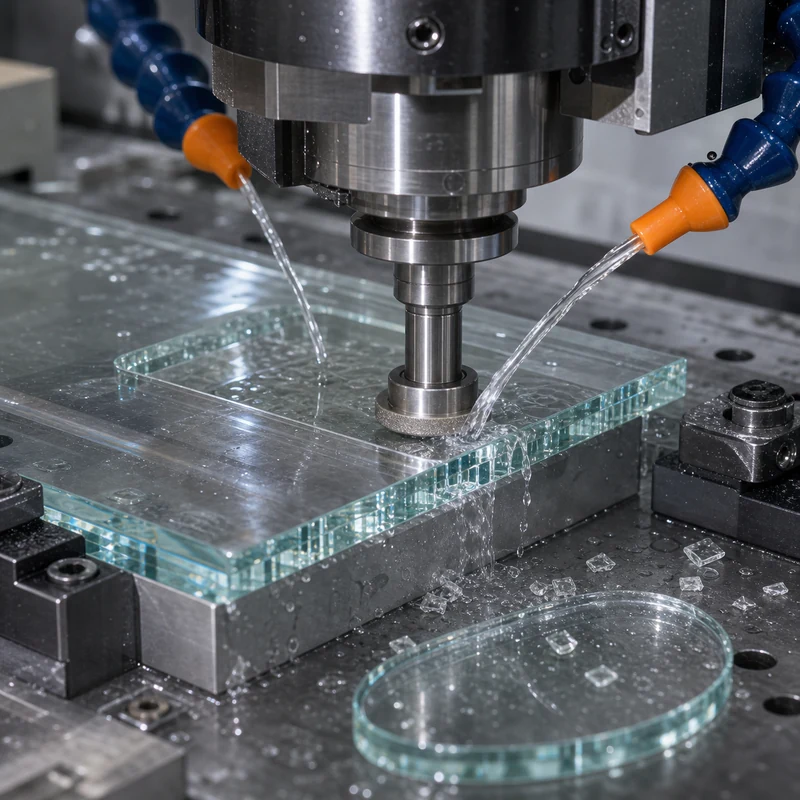
Glass CNC machining is the controlled cutting, drilling, grinding, or shaping of glass with computer-controlled equipment. Unlike aluminum or steel, glass is brittle and can crack if the tool, coolant, speed, fixture, or edge design is wrong. That makes process planning especially important.

Glass components appear in optics, displays, laboratory equipment, electronics, sensors, and decorative industrial products. When a project includes both glass and machined metal parts, MTSPi can help coordinate CNC machining services and assembly-oriented design feedback.

What Makes Glass Different From Metal

Metal usually deforms before it breaks; glass does not. Cutting forces can create microcracks that grow later during handling or assembly. Heat can also stress the material. For this reason, glass machining normally uses diamond tooling, controlled feeds, steady coolant, and careful support.

  • Avoid sharp internal corners where cracks can start.
  • Use generous edge radii or chamfers when possible.
  • Keep thin walls and narrow slots realistic for the glass thickness.
  • Specify edge finish requirements if the part will be visible or sealed.

Common Glass CNC Operations

Operation Purpose Key Concern
Cutting and profiling Create outside shapes or panels Edge chipping and dimensional control
Drilling Create mounting or fluid holes Breakout on exit side
Grinding Improve edge quality and size Heat, feed rate, and wheel condition
Pocketing or recessing Add shallow features Crack prevention and support
Polishing Improve optical or cosmetic finish Time and cost increase

Design Tips for Better Results

Designers should treat glass as a precision brittle material, not just a transparent sheet. Keep hole spacing away from edges, choose thickness that can survive handling, and avoid combining deep slots with sharp corners. If a part will be clamped, gasketed, or bonded, identify the contact zones on the drawing.

Material and Process Considerations

Different glass types behave differently. Soda-lime glass, borosilicate glass, quartz, and optical glass each require different tooling and parameters. When glass parts mate with metal housings, check tolerance stack-up carefully. Metal features may be produced by milling or turning, while glass may need looser allowances to prevent stress during assembly.

Inspection and Handling

Glass parts should be inspected for chips, cracks, edge quality, hole position, and thickness. Clean handling matters because small edge damage can turn into a later fracture. Packaging should prevent part-to-part contact, especially for polished or coated surfaces.

Related MTSPi Resources

FAQ

Can glass be CNC machined accurately?

Yes, but achievable tolerance depends on glass type, thickness, feature geometry, and edge finish requirements.

Why does glass chip during machining?

Chipping usually comes from brittle fracture, excessive force, poor support, or unsuitable tooling.

Can threaded holes be machined in glass?

It is generally risky. Inserts, bonded hardware, or through holes with fasteners are often safer design choices.

Categories
CNC Materials

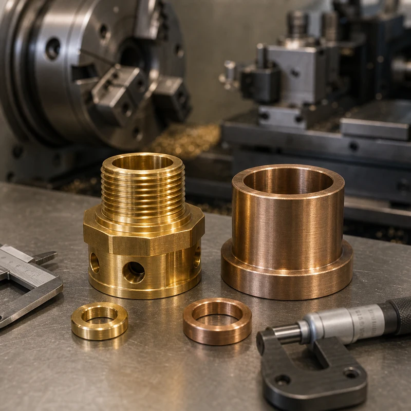
Brass vs Bronze: Composition, Machining, Strength, and Uses

Brass vs bronze is a practical question because the word is used in design reviews, RFQs, supplier audits, cost discussions, and quality reports. In manufacturing, it usually describes controlled material removal from metal or plastic stock to create a part with defined shape, dimensions, surface condition, and functional features. For buyers, the useful answer is not only the dictionary definition; it is how the process affects material choice, tolerance, lead time, finish, inspection, and supplier communication.

This guide combines common top-page coverage with CNC buyer details that are often missing: drawing requirements, process selection, cost drivers, inspection evidence, and realistic questions to ask before placing an order with MTSPi CNC / MEITESI.

Quick Answer

Brass vs bronze refers to a manufacturing subject connected to cutting, shaping, or removing material with controlled tools. In CNC work, the main decision is how to turn a drawing or model into a repeatable part without overpaying for unnecessary tolerance, finish, or setup complexity. A buyer should start with the part function, then define material, quantity, critical dimensions, finish, and inspection requirements.

When a part needs milled faces, pockets, slots, holes, or 3D profiles, a process-specific review can help match the geometry to a practical route. When the part includes round features, shafts, threads, bushings, or sleeves, turning may be more efficient than forcing the work into a milling setup.

Key Takeaways

  • Brass vs bronze should be understood through part function, not only a short definition.
  • The same term can mean different things in engineering, purchasing, shop-floor planning, and inspection.
  • Material grade, tolerance, surface finish, and batch quantity often matter more than the process name.
  • A clear 2D drawing is still important even when a 3D model is available.
  • The best supplier questions focus on risk: workholding, tool access, burrs, finish, measurement, and repeatability.

Definition and Core Meaning

Most leading educational pages explain brass vs bronze with a simple idea: controlled shaping of material into a desired part. That definition is useful, but it is incomplete for real sourcing work. A buyer also needs to know what will be held, where the cutting forces go, which surfaces are cosmetic, which dimensions control assembly, and what evidence proves the finished part is acceptable.

In a CNC project, the definition becomes more concrete. The process starts with a drawing, model, material, stock size, tools, fixtures, and inspection plan. If any of these are unclear, the quote may look fast but the project can still run into rework. MTSPi CNC reviews those details through drawing and model preparation before the machining route is finalized.

A useful way to think about the term is this: machining is not just cutting material away. It is a chain of decisions that includes programming, setup, tool selection, clamping, roughing, finishing, deburring, surface treatment, inspection, packaging, and communication. Each step can change cost and quality.

Question Simple answer Buyer detail that matters
What is being made? A part from raw material. The drawing should identify datums, threads, finish, tolerances, and critical surfaces.
How is material removed? By cutting tools or controlled energy. Tool access, chip control, heat, and workholding decide whether the process is stable.
What affects price? Machine time and material. Setup count, tolerance, finish, inspection, burr control, and quantity are often just as important.
How is quality confirmed? By inspection. Inspection should match the drawing risk with the right gauge, report, or sampling plan.

Main Process Categories

The most common process categories include milling, turning, drilling, boring, tapping, reaming, grinding, EDM, and finishing operations. Educational pages often list these as separate processes, but real parts often use several of them. A housing may need milling, drilling, tapping, deburring, bead blasting, and anodizing. A shaft may need turning, threading, grooving, polishing, and runout inspection.

Milling removes material with rotating cutters and is common for flat faces, pockets, slots, holes, and complex surfaces. Buyers can review CNC milling support when a part has prismatic geometry or multiple machined faces. Turning rotates the workpiece and is usually efficient for round parts, shafts, bushings, threaded pins, sleeves, and spacers; for these parts, CNC turning support may be the better starting point.

Drilling, boring, tapping, and reaming are hole-making or hole-finishing operations. They look simple on a drawing, but hole depth, thread engagement, position tolerance, burr direction, and access from one side or both sides can affect machining risk. Deep holes and small threaded holes deserve special attention before quoting.

A strong process choice also considers the order of operations. A hole drilled before milling may move slightly after material is removed around it. A thin wall roughed too aggressively may release stress and lose flatness. A cosmetic surface finished too early may be damaged during later clamping. These sequencing details are rarely visible in a simple definition, yet they are often the difference between a clean first batch and repeated correction.

Process Best suited for Common risk
Milling Flat faces, slots, pockets, 3D contours, hole patterns Long tool reach, vibration, internal corner radius, thin wall movement
Turning Shafts, bushings, sleeves, pins, threaded round parts Runout, concentricity, surface finish, slender-part deflection
Drilling and tapping Holes, threads, fastener locations Broken taps, wrong thread depth, burrs, poor position control
Grinding or fine finishing Tight surfaces and improved roughness Extra cost, measurement demand, and possible lead time increase

Materials and Manufacturing Considerations

Material choice changes nearly every part of brass vs bronze. Aluminum usually machines quickly and accepts many finishes, but thin walls may deform and cosmetic surfaces need protection. Stainless steel is strong and corrosion resistant, but it can work harden and increase tool wear. Brass cuts cleanly, copper needs careful burr and heat control, titanium demands conservative cutting and cooling, and engineering plastics need heat management and gentle workholding.

For metal projects, metal machining choices gives a useful way to compare alloy behavior before the RFQ is finalized. For projects where aluminum is likely, buyers should think about 6061, 7075, anodizing, flatness, and cost. Stainless steel buyers should pay attention to 304 versus 316, burr behavior, passivation, and the cost impact of tight tolerances.

Material is not only a performance choice. It is also a supply-chain choice. Availability, stock shape, minimum order size, certificate requirements, and substitute-grade permission can all affect quote speed. Buyers should state whether equivalent materials are allowed or whether the listed grade is mandatory.

Material Why buyers choose it Machining note
Aluminum Light weight, good machinability, many finish options Thin walls and cosmetic faces need careful sequence and handling.
Stainless steel Corrosion resistance, strength, clean appearance Tool wear, burrs, and work hardening can raise cost.
Brass or copper Conductivity, appearance, thread quality, fittings Copper can be gummy; brass is easier but alloy choice still matters.
Engineering plastics Weight reduction, insulation, wear behavior Heat, clamping, and burr control are important.

Cost, Tolerance, and Surface Finish Factors

Cost is often misunderstood because buyers compare only the unit price. A quote also reflects programming, setup, material preparation, fixture design, tool life, cutting time, deburring, finish, inspection, packaging, and delivery risk. A low quote may hide missing assumptions, while a high quote may include inspection or finish work that another supplier ignored.

Tolerances should protect function rather than decorate every feature. Tight dimensions on noncritical surfaces add cost without improving performance. A better approach is to mark critical features clearly and allow standard tolerances elsewhere. MTSPi CNC can review machining cost reduction checks when buyers want to reduce price without weakening the part.

Surface finish also changes the process. A visible aluminum panel may need careful tool paths, deburring, polishing, bead blasting, or anodizing. A hidden bracket may only need safe edges and functional holes. Surface expectations should be discussed before machining, especially when a post-machining finish will be applied after cutting.

Tolerance and finish should also be separated by purpose. A sealing face, bearing seat, threaded hole, and decorative cover do not fail in the same way. A sealing face may need flatness and surface roughness control. A bearing seat may need diameter, roundness, and runout. A visible cover may need consistent texture and protected edges. A hidden mounting plate may only need hole position and deburred edges. This distinction helps buyers spend money where it protects function.

Factor Why it changes the quote How to control it
Tight tolerance Requires slower cutting, stable setup, and more inspection Apply it only to functional features.
Small batch Setup cost is spread over fewer parts Combine parts or request quantity breaks.
Complex finish Adds handling, protection, and rework risk Define visible and hidden surfaces separately.
Incomplete drawing Supplier must guess or ask repeated questions Send drawing, model, material, finish, and quantity together.

Design and Drawing Notes for Better Results

Good design makes the important features reliable. Internal corners should allow realistic cutter radius. Deep pockets should allow tool access. Thin walls need enough stiffness for cutting and finishing. Threads should have clear depth and class. Holes should show whether they are blind, through, tapped, reamed, or counterbored.

A 3D model gives geometry, but the 2D drawing gives manufacturing intent. It should identify datums, tolerances, surface roughness, thread callouts, finish requirements, revision level, and inspection notes. Without this, the supplier may produce the shape correctly but miss the real acceptance standard.

For prototype work, prototype machining review helps confirm fit and function before the design moves to a production order. For repeated small batches, fixture notes, approved samples, and inspection records should be kept with the job so later orders do not restart the learning process.

Common Mistakes to Avoid

  • Using a broad term without explaining the part’s function or assembly risk.
  • Sending only a model when threads, finish, tolerances, and critical features are needed.
  • Specifying tight tolerances on every dimension instead of only where fit or performance requires them.
  • Leaving surface finish until after the machining process is already fixed.
  • Comparing supplier quotes without checking whether material, finish, inspection, and packing assumptions match.
  • Approving a prototype without recording what changed before low-volume production.

Supplier and Quotation Checklist

A good RFQ package helps suppliers answer quickly and accurately. It should include the model, drawing, material, quantity, finish, target lead time, inspection requirement, and any special packaging need. If the part is used with another component, include a short note about the mating feature or failure concern.

A capable supplier should explain the process route, not only state that the part can be made. Ask about workholding, tool access, burr control, inspection, and finish sequence. The answer should be specific enough that an engineer can see how the part will be controlled before shipment.

RFQ item What to provide Why it helps
3D model STEP or other usable CAD format Supports programming and geometry review.
2D drawing Tolerances, datums, threads, finish, revision Shows manufacturing intent and acceptance rules.
Material Grade, temper, certificate need, substitute permission Controls performance, cost, and availability.
Quantity Prototype and production breaks Helps choose fixture and process strategy.
Inspection Critical dimensions and report needs Prevents disputes after delivery.

How to Use This Information in a Real RFQ

After reading a definition or comparison, buyers should turn the information into a short RFQ note. The note can be simple: part function, material preference, expected quantity, important mating features, visible surfaces, and delivery target. This small addition helps the supplier understand why certain features matter and where standard manufacturing variation is acceptable.

For example, instead of asking only for a price, a buyer can write that two bores locate bearings, the top face is visible after assembly, the threaded holes need repeated installation, and the first order is for functional testing. That kind of note guides process planning, inspection priority, and packaging protection without making the project more complicated.

Specific Notes for Brass vs Bronze: Composition, Machining, Strength, and Uses

For the topic brass vs bronze, the most useful article is one that begins with the general definition but quickly moves into practical manufacturing choices. The front-page results commonly explain the concept well, yet they often leave buyers without enough detail about drawings, tolerance, cost, finishing, inspection, and supplier communication.

The better approach is to connect the concept to part features. If the part has milled pockets, use milling logic. If it has round geometry, evaluate turning. If it needs a smooth visible finish, plan surface treatment early. If it has tight functional dimensions, decide the inspection method before accepting the quote.

This is why MTSPi CNC / MEITESI treats every request as a connected manufacturing problem rather than a single-word process label. A clear drawing, suitable material, realistic tolerance, and measurable quality standard make the finished part easier to quote, easier to produce, and easier to approve.

Practical Buyer Scenario

Consider a buyer who searches for brass vs bronze because a new project has moved from concept to sourcing. The drawing shows a metal housing with two bearing bores, four mounting holes, a visible top surface, and a note calling for black finish. A basic educational explanation may help the buyer understand the term, but it will not answer the real purchasing questions: which faces are datums, whether the bores need inspection reports, whether the finish changes dimensions, and how the supplier will protect the visible surface during shipping.

In that situation, the buyer should not ask only whether the supplier can machine the part. A better request is to ask for a review of stock material, setup count, bore measurement, edge break, surface finish route, and packaging. If the housing is still being tested, prototype machining review can help confirm geometry before repeat orders. If the order will move into small batches, the buyer should ask which setup details can be reused and which dimensions need routine reporting.

This scenario shows why information articles should lead into real manufacturing decisions. The reader may begin with a broad question, but the project succeeds only when the definition becomes a drawing, a process route, a material order, a controlled finish, and an inspection method. That is the bridge between learning a term and buying usable parts.

Conclusion

Brass vs Bronze: Composition, Machining, Strength, and Uses should be understood as a practical manufacturing topic, not just a short definition. Buyers should use the concept to make better decisions about process selection, materials, tolerances, finish, cost, inspection, and supplier communication. With a clear RFQ package and a supplier that explains the route before production, MTSPi CNC / MEITESI can help turn general manufacturing knowledge into reliable machined parts.

FAQ

What does brass vs bronze mean in manufacturing?

It generally refers to a controlled way of shaping material, often by removing material with tools or machine processes. In CNC work, the meaning also includes programming, setup, workholding, finishing, and inspection.

What information should I send for a CNC quote?

Send a 3D model, 2D drawing, material grade, quantity, finish requirement, critical dimensions, thread notes, and any assembly concerns.

Is CNC machining always the best process?

No. It is excellent for precision parts, prototypes, low-volume production, metal components, and many plastic parts, but casting, forming, molding, or fabrication may suit some designs better.

Why do machining costs vary so much?

Costs vary because material, setup count, tolerance, finish, inspection, tooling, batch size, and lead time can change the real work behind the same-looking part.

How can buyers reduce machining risk?

Clarify drawings, mark critical features, choose suitable materials, avoid unnecessary tight tolerances, define finish expectations, and request inspection evidence that matches the part function.

Categories
CNC Materials

Plastic vs Metal Parts: Strength, Weight, Machining, Cost, and Design

Plastic vs metal parts is a practical question because the word is used in design reviews, RFQs, supplier audits, cost discussions, and quality reports. In manufacturing, it usually describes controlled material removal from metal or plastic stock to create a part with defined shape, dimensions, surface condition, and functional features. For buyers, the useful answer is not only the dictionary definition; it is how the process affects material choice, tolerance, lead time, finish, inspection, and supplier communication.

This guide combines common top-page coverage with CNC buyer details that are often missing: drawing requirements, process selection, cost drivers, inspection evidence, and realistic questions to ask before placing an order with MTSPi CNC / MEITESI.

Quick Answer

Plastic vs metal parts refers to a manufacturing subject connected to cutting, shaping, or removing material with controlled tools. In CNC work, the main decision is how to turn a drawing or model into a repeatable part without overpaying for unnecessary tolerance, finish, or setup complexity. A buyer should start with the part function, then define material, quantity, critical dimensions, finish, and inspection requirements.

When a part needs milled faces, pockets, slots, holes, or 3D profiles, a process-specific review can help match the geometry to a practical route. When the part includes round features, shafts, threads, bushings, or sleeves, turning may be more efficient than forcing the work into a milling setup.

Key Takeaways

  • Plastic vs metal parts should be understood through part function, not only a short definition.
  • The same term can mean different things in engineering, purchasing, shop-floor planning, and inspection.
  • Material grade, tolerance, surface finish, and batch quantity often matter more than the process name.
  • A clear 2D drawing is still important even when a 3D model is available.
  • The best supplier questions focus on risk: workholding, tool access, burrs, finish, measurement, and repeatability.

Definition and Core Meaning

Most leading educational pages explain plastic vs metal parts with a simple idea: controlled shaping of material into a desired part. That definition is useful, but it is incomplete for real sourcing work. A buyer also needs to know what will be held, where the cutting forces go, which surfaces are cosmetic, which dimensions control assembly, and what evidence proves the finished part is acceptable.

In a CNC project, the definition becomes more concrete. The process starts with a drawing, model, material, stock size, tools, fixtures, and inspection plan. If any of these are unclear, the quote may look fast but the project can still run into rework. MTSPi CNC reviews those details through drawing and model preparation before the machining route is finalized.

A useful way to think about the term is this: machining is not just cutting material away. It is a chain of decisions that includes programming, setup, tool selection, clamping, roughing, finishing, deburring, surface treatment, inspection, packaging, and communication. Each step can change cost and quality.

Question Simple answer Buyer detail that matters
What is being made? A part from raw material. The drawing should identify datums, threads, finish, tolerances, and critical surfaces.
How is material removed? By cutting tools or controlled energy. Tool access, chip control, heat, and workholding decide whether the process is stable.
What affects price? Machine time and material. Setup count, tolerance, finish, inspection, burr control, and quantity are often just as important.
How is quality confirmed? By inspection. Inspection should match the drawing risk with the right gauge, report, or sampling plan.

Main Process Categories

The most common process categories include milling, turning, drilling, boring, tapping, reaming, grinding, EDM, and finishing operations. Educational pages often list these as separate processes, but real parts often use several of them. A housing may need milling, drilling, tapping, deburring, bead blasting, and anodizing. A shaft may need turning, threading, grooving, polishing, and runout inspection.

Milling removes material with rotating cutters and is common for flat faces, pockets, slots, holes, and complex surfaces. Buyers can review CNC milling support when a part has prismatic geometry or multiple machined faces. Turning rotates the workpiece and is usually efficient for round parts, shafts, bushings, threaded pins, sleeves, and spacers; for these parts, CNC turning support may be the better starting point.

Drilling, boring, tapping, and reaming are hole-making or hole-finishing operations. They look simple on a drawing, but hole depth, thread engagement, position tolerance, burr direction, and access from one side or both sides can affect machining risk. Deep holes and small threaded holes deserve special attention before quoting.

A strong process choice also considers the order of operations. A hole drilled before milling may move slightly after material is removed around it. A thin wall roughed too aggressively may release stress and lose flatness. A cosmetic surface finished too early may be damaged during later clamping. These sequencing details are rarely visible in a simple definition, yet they are often the difference between a clean first batch and repeated correction.

Process Best suited for Common risk
Milling Flat faces, slots, pockets, 3D contours, hole patterns Long tool reach, vibration, internal corner radius, thin wall movement
Turning Shafts, bushings, sleeves, pins, threaded round parts Runout, concentricity, surface finish, slender-part deflection
Drilling and tapping Holes, threads, fastener locations Broken taps, wrong thread depth, burrs, poor position control
Grinding or fine finishing Tight surfaces and improved roughness Extra cost, measurement demand, and possible lead time increase

Materials and Manufacturing Considerations

Material choice changes nearly every part of plastic vs metal parts. Aluminum usually machines quickly and accepts many finishes, but thin walls may deform and cosmetic surfaces need protection. Stainless steel is strong and corrosion resistant, but it can work harden and increase tool wear. Brass cuts cleanly, copper needs careful burr and heat control, titanium demands conservative cutting and cooling, and engineering plastics need heat management and gentle workholding.

For metal projects, metal machining choices gives a useful way to compare alloy behavior before the RFQ is finalized. For projects where aluminum is likely, buyers should think about 6061, 7075, anodizing, flatness, and cost. Stainless steel buyers should pay attention to 304 versus 316, burr behavior, passivation, and the cost impact of tight tolerances.

Material is not only a performance choice. It is also a supply-chain choice. Availability, stock shape, minimum order size, certificate requirements, and substitute-grade permission can all affect quote speed. Buyers should state whether equivalent materials are allowed or whether the listed grade is mandatory.

Material Why buyers choose it Machining note
Aluminum Light weight, good machinability, many finish options Thin walls and cosmetic faces need careful sequence and handling.
Stainless steel Corrosion resistance, strength, clean appearance Tool wear, burrs, and work hardening can raise cost.
Brass or copper Conductivity, appearance, thread quality, fittings Copper can be gummy; brass is easier but alloy choice still matters.
Engineering plastics Weight reduction, insulation, wear behavior Heat, clamping, and burr control are important.

Cost, Tolerance, and Surface Finish Factors

Cost is often misunderstood because buyers compare only the unit price. A quote also reflects programming, setup, material preparation, fixture design, tool life, cutting time, deburring, finish, inspection, packaging, and delivery risk. A low quote may hide missing assumptions, while a high quote may include inspection or finish work that another supplier ignored.

Tolerances should protect function rather than decorate every feature. Tight dimensions on noncritical surfaces add cost without improving performance. A better approach is to mark critical features clearly and allow standard tolerances elsewhere. MTSPi CNC can review machining cost reduction checks when buyers want to reduce price without weakening the part.

Surface finish also changes the process. A visible aluminum panel may need careful tool paths, deburring, polishing, bead blasting, or anodizing. A hidden bracket may only need safe edges and functional holes. Surface expectations should be discussed before machining, especially when a post-machining finish will be applied after cutting.

Tolerance and finish should also be separated by purpose. A sealing face, bearing seat, threaded hole, and decorative cover do not fail in the same way. A sealing face may need flatness and surface roughness control. A bearing seat may need diameter, roundness, and runout. A visible cover may need consistent texture and protected edges. A hidden mounting plate may only need hole position and deburred edges. This distinction helps buyers spend money where it protects function.

Factor Why it changes the quote How to control it
Tight tolerance Requires slower cutting, stable setup, and more inspection Apply it only to functional features.
Small batch Setup cost is spread over fewer parts Combine parts or request quantity breaks.
Complex finish Adds handling, protection, and rework risk Define visible and hidden surfaces separately.
Incomplete drawing Supplier must guess or ask repeated questions Send drawing, model, material, finish, and quantity together.

Design and Drawing Notes for Better Results

Good design makes the important features reliable. Internal corners should allow realistic cutter radius. Deep pockets should allow tool access. Thin walls need enough stiffness for cutting and finishing. Threads should have clear depth and class. Holes should show whether they are blind, through, tapped, reamed, or counterbored.

A 3D model gives geometry, but the 2D drawing gives manufacturing intent. It should identify datums, tolerances, surface roughness, thread callouts, finish requirements, revision level, and inspection notes. Without this, the supplier may produce the shape correctly but miss the real acceptance standard.

For prototype work, prototype machining review helps confirm fit and function before the design moves to a production order. For repeated small batches, fixture notes, approved samples, and inspection records should be kept with the job so later orders do not restart the learning process.

Common Mistakes to Avoid

  • Using a broad term without explaining the part’s function or assembly risk.
  • Sending only a model when threads, finish, tolerances, and critical features are needed.
  • Specifying tight tolerances on every dimension instead of only where fit or performance requires them.
  • Leaving surface finish until after the machining process is already fixed.
  • Comparing supplier quotes without checking whether material, finish, inspection, and packing assumptions match.
  • Approving a prototype without recording what changed before low-volume production.

Supplier and Quotation Checklist

A good RFQ package helps suppliers answer quickly and accurately. It should include the model, drawing, material, quantity, finish, target lead time, inspection requirement, and any special packaging need. If the part is used with another component, include a short note about the mating feature or failure concern.

A capable supplier should explain the process route, not only state that the part can be made. Ask about workholding, tool access, burr control, inspection, and finish sequence. The answer should be specific enough that an engineer can see how the part will be controlled before shipment.

RFQ item What to provide Why it helps
3D model STEP or other usable CAD format Supports programming and geometry review.
2D drawing Tolerances, datums, threads, finish, revision Shows manufacturing intent and acceptance rules.
Material Grade, temper, certificate need, substitute permission Controls performance, cost, and availability.
Quantity Prototype and production breaks Helps choose fixture and process strategy.
Inspection Critical dimensions and report needs Prevents disputes after delivery.

How to Use This Information in a Real RFQ

After reading a definition or comparison, buyers should turn the information into a short RFQ note. The note can be simple: part function, material preference, expected quantity, important mating features, visible surfaces, and delivery target. This small addition helps the supplier understand why certain features matter and where standard manufacturing variation is acceptable.

For example, instead of asking only for a price, a buyer can write that two bores locate bearings, the top face is visible after assembly, the threaded holes need repeated installation, and the first order is for functional testing. That kind of note guides process planning, inspection priority, and packaging protection without making the project more complicated.

Specific Notes for Plastic vs Metal Parts: Strength, Weight, Machining, Cost, and Design

For the topic plastic vs metal parts, the most useful article is one that begins with the general definition but quickly moves into practical manufacturing choices. The front-page results commonly explain the concept well, yet they often leave buyers without enough detail about drawings, tolerance, cost, finishing, inspection, and supplier communication.

The better approach is to connect the concept to part features. If the part has milled pockets, use milling logic. If it has round geometry, evaluate turning. If it needs a smooth visible finish, plan surface treatment early. If it has tight functional dimensions, decide the inspection method before accepting the quote.

This is why MTSPi CNC / MEITESI treats every request as a connected manufacturing problem rather than a single-word process label. A clear drawing, suitable material, realistic tolerance, and measurable quality standard make the finished part easier to quote, easier to produce, and easier to approve.

Practical Buyer Scenario

Consider a buyer who searches for plastic vs metal parts because a new project has moved from concept to sourcing. The drawing shows a metal housing with two bearing bores, four mounting holes, a visible top surface, and a note calling for black finish. A basic educational explanation may help the buyer understand the term, but it will not answer the real purchasing questions: which faces are datums, whether the bores need inspection reports, whether the finish changes dimensions, and how the supplier will protect the visible surface during shipping.

In that situation, the buyer should not ask only whether the supplier can machine the part. A better request is to ask for a review of stock material, setup count, bore measurement, edge break, surface finish route, and packaging. If the housing is still being tested, prototype machining review can help confirm geometry before repeat orders. If the order will move into small batches, the buyer should ask which setup details can be reused and which dimensions need routine reporting.

This scenario shows why information articles should lead into real manufacturing decisions. The reader may begin with a broad question, but the project succeeds only when the definition becomes a drawing, a process route, a material order, a controlled finish, and an inspection method. That is the bridge between learning a term and buying usable parts.

Conclusion

Plastic vs Metal Parts: Strength, Weight, Machining, Cost, and Design should be understood as a practical manufacturing topic, not just a short definition. Buyers should use the concept to make better decisions about process selection, materials, tolerances, finish, cost, inspection, and supplier communication. With a clear RFQ package and a supplier that explains the route before production, MTSPi CNC / MEITESI can help turn general manufacturing knowledge into reliable machined parts.

FAQ

What does plastic vs metal parts mean in manufacturing?

It generally refers to a controlled way of shaping material, often by removing material with tools or machine processes. In CNC work, the meaning also includes programming, setup, workholding, finishing, and inspection.

What information should I send for a CNC quote?

Send a 3D model, 2D drawing, material grade, quantity, finish requirement, critical dimensions, thread notes, and any assembly concerns.

Is CNC machining always the best process?

No. It is excellent for precision parts, prototypes, low-volume production, metal components, and many plastic parts, but casting, forming, molding, or fabrication may suit some designs better.

Why do machining costs vary so much?

Costs vary because material, setup count, tolerance, finish, inspection, tooling, batch size, and lead time can change the real work behind the same-looking part.

How can buyers reduce machining risk?

Clarify drawings, mark critical features, choose suitable materials, avoid unnecessary tight tolerances, define finish expectations, and request inspection evidence that matches the part function.

Categories
CNC Materials

Titanium vs Stainless Steel: Strength, Weight, Machining, and Cost

Titanium vs stainless steel is a practical question because the word is used in design reviews, RFQs, supplier audits, cost discussions, and quality reports. In manufacturing, it usually describes controlled material removal from metal or plastic stock to create a part with defined shape, dimensions, surface condition, and functional features. For buyers, the useful answer is not only the dictionary definition; it is how the process affects material choice, tolerance, lead time, finish, inspection, and supplier communication.

This guide combines common top-page coverage with CNC buyer details that are often missing: drawing requirements, process selection, cost drivers, inspection evidence, and realistic questions to ask before placing an order with MTSPi CNC / MEITESI.

Quick Answer

Titanium vs stainless steel refers to a manufacturing subject connected to cutting, shaping, or removing material with controlled tools. In CNC work, the main decision is how to turn a drawing or model into a repeatable part without overpaying for unnecessary tolerance, finish, or setup complexity. A buyer should start with the part function, then define material, quantity, critical dimensions, finish, and inspection requirements.

When a part needs milled faces, pockets, slots, holes, or 3D profiles, a process-specific review can help match the geometry to a practical route. When the part includes round features, shafts, threads, bushings, or sleeves, turning may be more efficient than forcing the work into a milling setup.

Key Takeaways

  • Titanium vs stainless steel should be understood through part function, not only a short definition.
  • The same term can mean different things in engineering, purchasing, shop-floor planning, and inspection.
  • Material grade, tolerance, surface finish, and batch quantity often matter more than the process name.
  • A clear 2D drawing is still important even when a 3D model is available.
  • The best supplier questions focus on risk: workholding, tool access, burrs, finish, measurement, and repeatability.

Definition and Core Meaning

Most leading educational pages explain titanium vs stainless steel with a simple idea: controlled shaping of material into a desired part. That definition is useful, but it is incomplete for real sourcing work. A buyer also needs to know what will be held, where the cutting forces go, which surfaces are cosmetic, which dimensions control assembly, and what evidence proves the finished part is acceptable.

In a CNC project, the definition becomes more concrete. The process starts with a drawing, model, material, stock size, tools, fixtures, and inspection plan. If any of these are unclear, the quote may look fast but the project can still run into rework. MTSPi CNC reviews those details through drawing and model preparation before the machining route is finalized.

A useful way to think about the term is this: machining is not just cutting material away. It is a chain of decisions that includes programming, setup, tool selection, clamping, roughing, finishing, deburring, surface treatment, inspection, packaging, and communication. Each step can change cost and quality.

Question Simple answer Buyer detail that matters
What is being made? A part from raw material. The drawing should identify datums, threads, finish, tolerances, and critical surfaces.
How is material removed? By cutting tools or controlled energy. Tool access, chip control, heat, and workholding decide whether the process is stable.
What affects price? Machine time and material. Setup count, tolerance, finish, inspection, burr control, and quantity are often just as important.
How is quality confirmed? By inspection. Inspection should match the drawing risk with the right gauge, report, or sampling plan.

Main Process Categories

The most common process categories include milling, turning, drilling, boring, tapping, reaming, grinding, EDM, and finishing operations. Educational pages often list these as separate processes, but real parts often use several of them. A housing may need milling, drilling, tapping, deburring, bead blasting, and anodizing. A shaft may need turning, threading, grooving, polishing, and runout inspection.

Milling removes material with rotating cutters and is common for flat faces, pockets, slots, holes, and complex surfaces. Buyers can review CNC milling support when a part has prismatic geometry or multiple machined faces. Turning rotates the workpiece and is usually efficient for round parts, shafts, bushings, threaded pins, sleeves, and spacers; for these parts, CNC turning support may be the better starting point.

Drilling, boring, tapping, and reaming are hole-making or hole-finishing operations. They look simple on a drawing, but hole depth, thread engagement, position tolerance, burr direction, and access from one side or both sides can affect machining risk. Deep holes and small threaded holes deserve special attention before quoting.

A strong process choice also considers the order of operations. A hole drilled before milling may move slightly after material is removed around it. A thin wall roughed too aggressively may release stress and lose flatness. A cosmetic surface finished too early may be damaged during later clamping. These sequencing details are rarely visible in a simple definition, yet they are often the difference between a clean first batch and repeated correction.

Process Best suited for Common risk
Milling Flat faces, slots, pockets, 3D contours, hole patterns Long tool reach, vibration, internal corner radius, thin wall movement
Turning Shafts, bushings, sleeves, pins, threaded round parts Runout, concentricity, surface finish, slender-part deflection
Drilling and tapping Holes, threads, fastener locations Broken taps, wrong thread depth, burrs, poor position control
Grinding or fine finishing Tight surfaces and improved roughness Extra cost, measurement demand, and possible lead time increase

Materials and Manufacturing Considerations

Material choice changes nearly every part of titanium vs stainless steel. Aluminum usually machines quickly and accepts many finishes, but thin walls may deform and cosmetic surfaces need protection. Stainless steel is strong and corrosion resistant, but it can work harden and increase tool wear. Brass cuts cleanly, copper needs careful burr and heat control, titanium demands conservative cutting and cooling, and engineering plastics need heat management and gentle workholding.

For metal projects, metal machining choices gives a useful way to compare alloy behavior before the RFQ is finalized. For projects where aluminum is likely, buyers should think about 6061, 7075, anodizing, flatness, and cost. Stainless steel buyers should pay attention to 304 versus 316, burr behavior, passivation, and the cost impact of tight tolerances.

Material is not only a performance choice. It is also a supply-chain choice. Availability, stock shape, minimum order size, certificate requirements, and substitute-grade permission can all affect quote speed. Buyers should state whether equivalent materials are allowed or whether the listed grade is mandatory.

Material Why buyers choose it Machining note
Aluminum Light weight, good machinability, many finish options Thin walls and cosmetic faces need careful sequence and handling.
Stainless steel Corrosion resistance, strength, clean appearance Tool wear, burrs, and work hardening can raise cost.
Brass or copper Conductivity, appearance, thread quality, fittings Copper can be gummy; brass is easier but alloy choice still matters.
Engineering plastics Weight reduction, insulation, wear behavior Heat, clamping, and burr control are important.

Cost, Tolerance, and Surface Finish Factors

Cost is often misunderstood because buyers compare only the unit price. A quote also reflects programming, setup, material preparation, fixture design, tool life, cutting time, deburring, finish, inspection, packaging, and delivery risk. A low quote may hide missing assumptions, while a high quote may include inspection or finish work that another supplier ignored.

Tolerances should protect function rather than decorate every feature. Tight dimensions on noncritical surfaces add cost without improving performance. A better approach is to mark critical features clearly and allow standard tolerances elsewhere. MTSPi CNC can review machining cost reduction checks when buyers want to reduce price without weakening the part.

Surface finish also changes the process. A visible aluminum panel may need careful tool paths, deburring, polishing, bead blasting, or anodizing. A hidden bracket may only need safe edges and functional holes. Surface expectations should be discussed before machining, especially when a post-machining finish will be applied after cutting.

Tolerance and finish should also be separated by purpose. A sealing face, bearing seat, threaded hole, and decorative cover do not fail in the same way. A sealing face may need flatness and surface roughness control. A bearing seat may need diameter, roundness, and runout. A visible cover may need consistent texture and protected edges. A hidden mounting plate may only need hole position and deburred edges. This distinction helps buyers spend money where it protects function.

Factor Why it changes the quote How to control it
Tight tolerance Requires slower cutting, stable setup, and more inspection Apply it only to functional features.
Small batch Setup cost is spread over fewer parts Combine parts or request quantity breaks.
Complex finish Adds handling, protection, and rework risk Define visible and hidden surfaces separately.
Incomplete drawing Supplier must guess or ask repeated questions Send drawing, model, material, finish, and quantity together.

Design and Drawing Notes for Better Results

Good design makes the important features reliable. Internal corners should allow realistic cutter radius. Deep pockets should allow tool access. Thin walls need enough stiffness for cutting and finishing. Threads should have clear depth and class. Holes should show whether they are blind, through, tapped, reamed, or counterbored.

A 3D model gives geometry, but the 2D drawing gives manufacturing intent. It should identify datums, tolerances, surface roughness, thread callouts, finish requirements, revision level, and inspection notes. Without this, the supplier may produce the shape correctly but miss the real acceptance standard.

For prototype work, prototype machining review helps confirm fit and function before the design moves to a production order. For repeated small batches, fixture notes, approved samples, and inspection records should be kept with the job so later orders do not restart the learning process.

Common Mistakes to Avoid

  • Using a broad term without explaining the part’s function or assembly risk.
  • Sending only a model when threads, finish, tolerances, and critical features are needed.
  • Specifying tight tolerances on every dimension instead of only where fit or performance requires them.
  • Leaving surface finish until after the machining process is already fixed.
  • Comparing supplier quotes without checking whether material, finish, inspection, and packing assumptions match.
  • Approving a prototype without recording what changed before low-volume production.

Supplier and Quotation Checklist

A good RFQ package helps suppliers answer quickly and accurately. It should include the model, drawing, material, quantity, finish, target lead time, inspection requirement, and any special packaging need. If the part is used with another component, include a short note about the mating feature or failure concern.

A capable supplier should explain the process route, not only state that the part can be made. Ask about workholding, tool access, burr control, inspection, and finish sequence. The answer should be specific enough that an engineer can see how the part will be controlled before shipment.

RFQ item What to provide Why it helps
3D model STEP or other usable CAD format Supports programming and geometry review.
2D drawing Tolerances, datums, threads, finish, revision Shows manufacturing intent and acceptance rules.
Material Grade, temper, certificate need, substitute permission Controls performance, cost, and availability.
Quantity Prototype and production breaks Helps choose fixture and process strategy.
Inspection Critical dimensions and report needs Prevents disputes after delivery.

How to Use This Information in a Real RFQ

After reading a definition or comparison, buyers should turn the information into a short RFQ note. The note can be simple: part function, material preference, expected quantity, important mating features, visible surfaces, and delivery target. This small addition helps the supplier understand why certain features matter and where standard manufacturing variation is acceptable.

For example, instead of asking only for a price, a buyer can write that two bores locate bearings, the top face is visible after assembly, the threaded holes need repeated installation, and the first order is for functional testing. That kind of note guides process planning, inspection priority, and packaging protection without making the project more complicated.

Specific Notes for Titanium vs Stainless Steel: Strength, Weight, Machining, and Cost

For the topic titanium vs stainless steel, the most useful article is one that begins with the general definition but quickly moves into practical manufacturing choices. The front-page results commonly explain the concept well, yet they often leave buyers without enough detail about drawings, tolerance, cost, finishing, inspection, and supplier communication.

The better approach is to connect the concept to part features. If the part has milled pockets, use milling logic. If it has round geometry, evaluate turning. If it needs a smooth visible finish, plan surface treatment early. If it has tight functional dimensions, decide the inspection method before accepting the quote.

This is why MTSPi CNC / MEITESI treats every request as a connected manufacturing problem rather than a single-word process label. A clear drawing, suitable material, realistic tolerance, and measurable quality standard make the finished part easier to quote, easier to produce, and easier to approve.

Practical Buyer Scenario

Consider a buyer who searches for titanium vs stainless steel because a new project has moved from concept to sourcing. The drawing shows a metal housing with two bearing bores, four mounting holes, a visible top surface, and a note calling for black finish. A basic educational explanation may help the buyer understand the term, but it will not answer the real purchasing questions: which faces are datums, whether the bores need inspection reports, whether the finish changes dimensions, and how the supplier will protect the visible surface during shipping.

In that situation, the buyer should not ask only whether the supplier can machine the part. A better request is to ask for a review of stock material, setup count, bore measurement, edge break, surface finish route, and packaging. If the housing is still being tested, prototype machining review can help confirm geometry before repeat orders. If the order will move into small batches, the buyer should ask which setup details can be reused and which dimensions need routine reporting.

This scenario shows why information articles should lead into real manufacturing decisions. The reader may begin with a broad question, but the project succeeds only when the definition becomes a drawing, a process route, a material order, a controlled finish, and an inspection method. That is the bridge between learning a term and buying usable parts.

Conclusion

Titanium vs Stainless Steel: Strength, Weight, Machining, and Cost should be understood as a practical manufacturing topic, not just a short definition. Buyers should use the concept to make better decisions about process selection, materials, tolerances, finish, cost, inspection, and supplier communication. With a clear RFQ package and a supplier that explains the route before production, MTSPi CNC / MEITESI can help turn general manufacturing knowledge into reliable machined parts.

FAQ

What does titanium vs stainless steel mean in manufacturing?

It generally refers to a controlled way of shaping material, often by removing material with tools or machine processes. In CNC work, the meaning also includes programming, setup, workholding, finishing, and inspection.

What information should I send for a CNC quote?

Send a 3D model, 2D drawing, material grade, quantity, finish requirement, critical dimensions, thread notes, and any assembly concerns.

Is CNC machining always the best process?

No. It is excellent for precision parts, prototypes, low-volume production, metal components, and many plastic parts, but casting, forming, molding, or fabrication may suit some designs better.

Why do machining costs vary so much?

Costs vary because material, setup count, tolerance, finish, inspection, tooling, batch size, and lead time can change the real work behind the same-looking part.

How can buyers reduce machining risk?

Clarify drawings, mark critical features, choose suitable materials, avoid unnecessary tight tolerances, define finish expectations, and request inspection evidence that matches the part function.

Categories
CNC Materials

6061 vs 7075 Aluminum: Strength, Machining, Anodizing, and Cost

6061 vs 7075 aluminum is a practical question because the word is used in design reviews, RFQs, supplier audits, cost discussions, and quality reports. In manufacturing, it usually describes controlled material removal from metal or plastic stock to create a part with defined shape, dimensions, surface condition, and functional features. For buyers, the useful answer is not only the dictionary definition; it is how the process affects material choice, tolerance, lead time, finish, inspection, and supplier communication.

This guide combines common top-page coverage with CNC buyer details that are often missing: drawing requirements, process selection, cost drivers, inspection evidence, and realistic questions to ask before placing an order with MTSPi CNC / MEITESI.

Quick Answer

6061 vs 7075 aluminum refers to a manufacturing subject connected to cutting, shaping, or removing material with controlled tools. In CNC work, the main decision is how to turn a drawing or model into a repeatable part without overpaying for unnecessary tolerance, finish, or setup complexity. A buyer should start with the part function, then define material, quantity, critical dimensions, finish, and inspection requirements.

When a part needs milled faces, pockets, slots, holes, or 3D profiles, a process-specific review can help match the geometry to a practical route. When the part includes round features, shafts, threads, bushings, or sleeves, turning may be more efficient than forcing the work into a milling setup.

Key Takeaways

  • 6061 vs 7075 aluminum should be understood through part function, not only a short definition.
  • The same term can mean different things in engineering, purchasing, shop-floor planning, and inspection.
  • Material grade, tolerance, surface finish, and batch quantity often matter more than the process name.
  • A clear 2D drawing is still important even when a 3D model is available.
  • The best supplier questions focus on risk: workholding, tool access, burrs, finish, measurement, and repeatability.

Definition and Core Meaning

Most leading educational pages explain 6061 vs 7075 aluminum with a simple idea: controlled shaping of material into a desired part. That definition is useful, but it is incomplete for real sourcing work. A buyer also needs to know what will be held, where the cutting forces go, which surfaces are cosmetic, which dimensions control assembly, and what evidence proves the finished part is acceptable.

In a CNC project, the definition becomes more concrete. The process starts with a drawing, model, material, stock size, tools, fixtures, and inspection plan. If any of these are unclear, the quote may look fast but the project can still run into rework. MTSPi CNC reviews those details through drawing and model preparation before the machining route is finalized.

A useful way to think about the term is this: machining is not just cutting material away. It is a chain of decisions that includes programming, setup, tool selection, clamping, roughing, finishing, deburring, surface treatment, inspection, packaging, and communication. Each step can change cost and quality.

Question Simple answer Buyer detail that matters
What is being made? A part from raw material. The drawing should identify datums, threads, finish, tolerances, and critical surfaces.
How is material removed? By cutting tools or controlled energy. Tool access, chip control, heat, and workholding decide whether the process is stable.
What affects price? Machine time and material. Setup count, tolerance, finish, inspection, burr control, and quantity are often just as important.
How is quality confirmed? By inspection. Inspection should match the drawing risk with the right gauge, report, or sampling plan.

Main Process Categories

The most common process categories include milling, turning, drilling, boring, tapping, reaming, grinding, EDM, and finishing operations. Educational pages often list these as separate processes, but real parts often use several of them. A housing may need milling, drilling, tapping, deburring, bead blasting, and anodizing. A shaft may need turning, threading, grooving, polishing, and runout inspection.

Milling removes material with rotating cutters and is common for flat faces, pockets, slots, holes, and complex surfaces. Buyers can review CNC milling support when a part has prismatic geometry or multiple machined faces. Turning rotates the workpiece and is usually efficient for round parts, shafts, bushings, threaded pins, sleeves, and spacers; for these parts, CNC turning support may be the better starting point.

Drilling, boring, tapping, and reaming are hole-making or hole-finishing operations. They look simple on a drawing, but hole depth, thread engagement, position tolerance, burr direction, and access from one side or both sides can affect machining risk. Deep holes and small threaded holes deserve special attention before quoting.

A strong process choice also considers the order of operations. A hole drilled before milling may move slightly after material is removed around it. A thin wall roughed too aggressively may release stress and lose flatness. A cosmetic surface finished too early may be damaged during later clamping. These sequencing details are rarely visible in a simple definition, yet they are often the difference between a clean first batch and repeated correction.

Process Best suited for Common risk
Milling Flat faces, slots, pockets, 3D contours, hole patterns Long tool reach, vibration, internal corner radius, thin wall movement
Turning Shafts, bushings, sleeves, pins, threaded round parts Runout, concentricity, surface finish, slender-part deflection
Drilling and tapping Holes, threads, fastener locations Broken taps, wrong thread depth, burrs, poor position control
Grinding or fine finishing Tight surfaces and improved roughness Extra cost, measurement demand, and possible lead time increase

Materials and Manufacturing Considerations

Material choice changes nearly every part of 6061 vs 7075 aluminum. Aluminum usually machines quickly and accepts many finishes, but thin walls may deform and cosmetic surfaces need protection. Stainless steel is strong and corrosion resistant, but it can work harden and increase tool wear. Brass cuts cleanly, copper needs careful burr and heat control, titanium demands conservative cutting and cooling, and engineering plastics need heat management and gentle workholding.

For metal projects, metal machining choices gives a useful way to compare alloy behavior before the RFQ is finalized. For projects where aluminum is likely, buyers should think about 6061, 7075, anodizing, flatness, and cost. Stainless steel buyers should pay attention to 304 versus 316, burr behavior, passivation, and the cost impact of tight tolerances.

Material is not only a performance choice. It is also a supply-chain choice. Availability, stock shape, minimum order size, certificate requirements, and substitute-grade permission can all affect quote speed. Buyers should state whether equivalent materials are allowed or whether the listed grade is mandatory.

Material Why buyers choose it Machining note
Aluminum Light weight, good machinability, many finish options Thin walls and cosmetic faces need careful sequence and handling.
Stainless steel Corrosion resistance, strength, clean appearance Tool wear, burrs, and work hardening can raise cost.
Brass or copper Conductivity, appearance, thread quality, fittings Copper can be gummy; brass is easier but alloy choice still matters.
Engineering plastics Weight reduction, insulation, wear behavior Heat, clamping, and burr control are important.

Cost, Tolerance, and Surface Finish Factors

Cost is often misunderstood because buyers compare only the unit price. A quote also reflects programming, setup, material preparation, fixture design, tool life, cutting time, deburring, finish, inspection, packaging, and delivery risk. A low quote may hide missing assumptions, while a high quote may include inspection or finish work that another supplier ignored.

Tolerances should protect function rather than decorate every feature. Tight dimensions on noncritical surfaces add cost without improving performance. A better approach is to mark critical features clearly and allow standard tolerances elsewhere. MTSPi CNC can review machining cost reduction checks when buyers want to reduce price without weakening the part.

Surface finish also changes the process. A visible aluminum panel may need careful tool paths, deburring, polishing, bead blasting, or anodizing. A hidden bracket may only need safe edges and functional holes. Surface expectations should be discussed before machining, especially when a post-machining finish will be applied after cutting.

Tolerance and finish should also be separated by purpose. A sealing face, bearing seat, threaded hole, and decorative cover do not fail in the same way. A sealing face may need flatness and surface roughness control. A bearing seat may need diameter, roundness, and runout. A visible cover may need consistent texture and protected edges. A hidden mounting plate may only need hole position and deburred edges. This distinction helps buyers spend money where it protects function.

Factor Why it changes the quote How to control it
Tight tolerance Requires slower cutting, stable setup, and more inspection Apply it only to functional features.
Small batch Setup cost is spread over fewer parts Combine parts or request quantity breaks.
Complex finish Adds handling, protection, and rework risk Define visible and hidden surfaces separately.
Incomplete drawing Supplier must guess or ask repeated questions Send drawing, model, material, finish, and quantity together.

Design and Drawing Notes for Better Results

Good design makes the important features reliable. Internal corners should allow realistic cutter radius. Deep pockets should allow tool access. Thin walls need enough stiffness for cutting and finishing. Threads should have clear depth and class. Holes should show whether they are blind, through, tapped, reamed, or counterbored.

A 3D model gives geometry, but the 2D drawing gives manufacturing intent. It should identify datums, tolerances, surface roughness, thread callouts, finish requirements, revision level, and inspection notes. Without this, the supplier may produce the shape correctly but miss the real acceptance standard.

For prototype work, prototype machining review helps confirm fit and function before the design moves to a production order. For repeated small batches, fixture notes, approved samples, and inspection records should be kept with the job so later orders do not restart the learning process.

Common Mistakes to Avoid

  • Using a broad term without explaining the part’s function or assembly risk.
  • Sending only a model when threads, finish, tolerances, and critical features are needed.
  • Specifying tight tolerances on every dimension instead of only where fit or performance requires them.
  • Leaving surface finish until after the machining process is already fixed.
  • Comparing supplier quotes without checking whether material, finish, inspection, and packing assumptions match.
  • Approving a prototype without recording what changed before low-volume production.

Supplier and Quotation Checklist

A good RFQ package helps suppliers answer quickly and accurately. It should include the model, drawing, material, quantity, finish, target lead time, inspection requirement, and any special packaging need. If the part is used with another component, include a short note about the mating feature or failure concern.

A capable supplier should explain the process route, not only state that the part can be made. Ask about workholding, tool access, burr control, inspection, and finish sequence. The answer should be specific enough that an engineer can see how the part will be controlled before shipment.

RFQ item What to provide Why it helps
3D model STEP or other usable CAD format Supports programming and geometry review.
2D drawing Tolerances, datums, threads, finish, revision Shows manufacturing intent and acceptance rules.
Material Grade, temper, certificate need, substitute permission Controls performance, cost, and availability.
Quantity Prototype and production breaks Helps choose fixture and process strategy.
Inspection Critical dimensions and report needs Prevents disputes after delivery.

How to Use This Information in a Real RFQ

After reading a definition or comparison, buyers should turn the information into a short RFQ note. The note can be simple: part function, material preference, expected quantity, important mating features, visible surfaces, and delivery target. This small addition helps the supplier understand why certain features matter and where standard manufacturing variation is acceptable.

For example, instead of asking only for a price, a buyer can write that two bores locate bearings, the top face is visible after assembly, the threaded holes need repeated installation, and the first order is for functional testing. That kind of note guides process planning, inspection priority, and packaging protection without making the project more complicated.

Specific Notes for 6061 vs 7075 Aluminum: Strength, Machining, Anodizing, and Cost

For the topic 6061 vs 7075 aluminum, the most useful article is one that begins with the general definition but quickly moves into practical manufacturing choices. The front-page results commonly explain the concept well, yet they often leave buyers without enough detail about drawings, tolerance, cost, finishing, inspection, and supplier communication.

The better approach is to connect the concept to part features. If the part has milled pockets, use milling logic. If it has round geometry, evaluate turning. If it needs a smooth visible finish, plan surface treatment early. If it has tight functional dimensions, decide the inspection method before accepting the quote.

This is why MTSPi CNC / MEITESI treats every request as a connected manufacturing problem rather than a single-word process label. A clear drawing, suitable material, realistic tolerance, and measurable quality standard make the finished part easier to quote, easier to produce, and easier to approve.

Practical Buyer Scenario

Consider a buyer who searches for 6061 vs 7075 aluminum because a new project has moved from concept to sourcing. The drawing shows a metal housing with two bearing bores, four mounting holes, a visible top surface, and a note calling for black finish. A basic educational explanation may help the buyer understand the term, but it will not answer the real purchasing questions: which faces are datums, whether the bores need inspection reports, whether the finish changes dimensions, and how the supplier will protect the visible surface during shipping.

In that situation, the buyer should not ask only whether the supplier can machine the part. A better request is to ask for a review of stock material, setup count, bore measurement, edge break, surface finish route, and packaging. If the housing is still being tested, prototype machining review can help confirm geometry before repeat orders. If the order will move into small batches, the buyer should ask which setup details can be reused and which dimensions need routine reporting.

This scenario shows why information articles should lead into real manufacturing decisions. The reader may begin with a broad question, but the project succeeds only when the definition becomes a drawing, a process route, a material order, a controlled finish, and an inspection method. That is the bridge between learning a term and buying usable parts.

Conclusion

6061 vs 7075 Aluminum: Strength, Machining, Anodizing, and Cost should be understood as a practical manufacturing topic, not just a short definition. Buyers should use the concept to make better decisions about process selection, materials, tolerances, finish, cost, inspection, and supplier communication. With a clear RFQ package and a supplier that explains the route before production, MTSPi CNC / MEITESI can help turn general manufacturing knowledge into reliable machined parts.

FAQ

What does 6061 vs 7075 aluminum mean in manufacturing?

It generally refers to a controlled way of shaping material, often by removing material with tools or machine processes. In CNC work, the meaning also includes programming, setup, workholding, finishing, and inspection.

What information should I send for a CNC quote?

Send a 3D model, 2D drawing, material grade, quantity, finish requirement, critical dimensions, thread notes, and any assembly concerns.

Is CNC machining always the best process?

No. It is excellent for precision parts, prototypes, low-volume production, metal components, and many plastic parts, but casting, forming, molding, or fabrication may suit some designs better.

Why do machining costs vary so much?

Costs vary because material, setup count, tolerance, finish, inspection, tooling, batch size, and lead time can change the real work behind the same-looking part.

How can buyers reduce machining risk?

Clarify drawings, mark critical features, choose suitable materials, avoid unnecessary tight tolerances, define finish expectations, and request inspection evidence that matches the part function.

Request A Quote

We'll Send You Back with Price Immediately!

DEC 1-31

XMAS SPECEIL

Up to

40% off

6061 vs 7075 Aluminum: Strength, Machining, Anodizing, and Cost

We'll Send You Back with Price Immediately!