Categories
Blog Guides Manufacturing Process Comparisons

Industrial 3D Printing Processes: A Requirement-Based Selection Guide

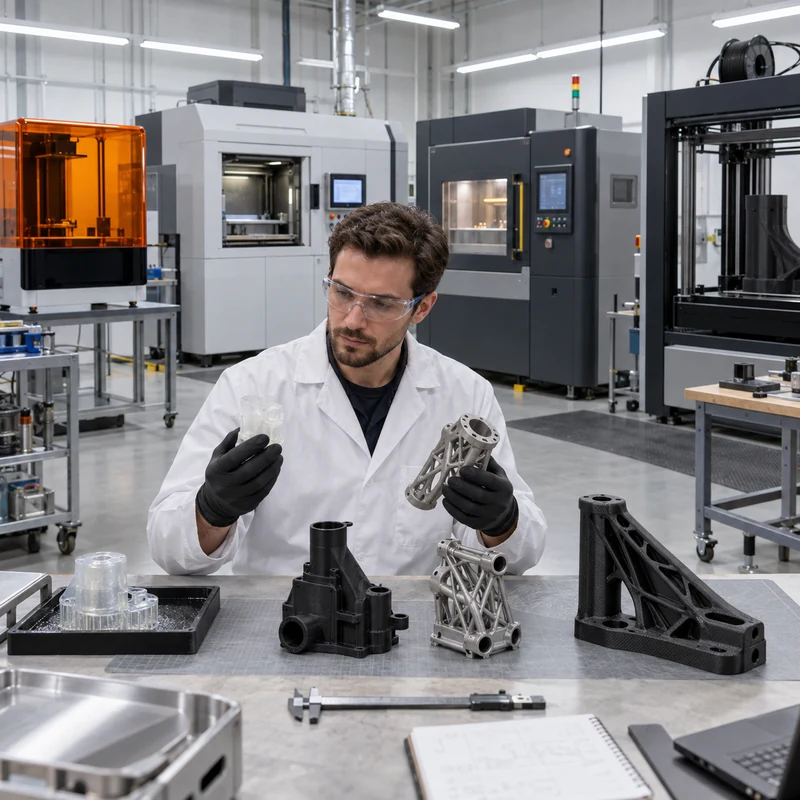
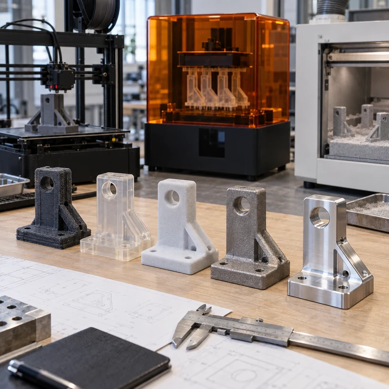
Industrial 3D printing is not one process. Resin vat systems, polymer powder-bed machines, metal powder fusion, filament extrusion, and pellet extrusion produce very different parts even when they start from the same CAD file. The best choice depends on the requirement that cannot be compromised.

A useful selection method filters processes in order: material, build size, feature detail, service conditions, geometry, surface requirements, and quantity. This prevents a visually attractive prototype from being mistaken for a production-capable part.

Quick Answer

Use SLA or DLP for fine visual detail, SLS or MJF for durable nylon geometry without support structures, FDM for economical engineering thermoplastics, FGF for very large parts, and metal powder-bed fusion for high-value metal geometry. Add CNC machining when datums, bores, sealing faces, or tight fits exceed as-printed capability.

Comparison at a Glance

Process family Typical material Best fit Key limitation
SLA / DLP Photopolymer resin Detailed visual and fit models Creep, UV aging, and brittle grades
SLS / MJF Nylon powder Functional parts and complex channels Grainy surface and moderate tolerance
Metal powder fusion Steel, aluminum, titanium, nickel alloy Load-bearing metal geometry Cost, supports, stress relief, finishing
FDM Filament thermoplastics Fixtures, housings, and heat-resistant prototypes Layer anisotropy and visible layer lines
FGF Pellet thermoplastics Large tools, patterns, and structures Coarse detail and machining allowance

1. Start With Material and Service Conditions

Ask whether the part must be metal, a production thermoplastic, an elastomer, transparent, sterilizable, chemically resistant, or stable at temperature. Material requirements remove unsuitable processes faster than comparing nominal resolution.

Resin can reproduce small details but usually does not behave like molded ABS or polycarbonate. Nylon powder processes offer better toughness for functional assemblies. FDM and FGF can use engineering thermoplastics, but orientation affects strength. Metal systems serve demanding thermal and mechanical duties, with post-build heat treatment often required.

  • Define sustained and peak temperature
  • List fluids, cleaners, and UV exposure
  • Separate cosmetic tests from structural tests
  • Identify flame, medical, or aerospace documentation needs

2. Check the Complete Build Envelope

A part must fit along all three machine axes, including supports and orientation. Splitting a large model introduces joints, alignment error, finishing labor, and weaker load paths.

Large-format extrusion is often more practical than joining many small prints. Conversely, a huge machine does not guarantee fine features: nozzle size, layer height, and thermal movement still control detail.

3. Separate Resolution From Tolerance

Layer height and pixel size describe the machine’s smallest increments, not guaranteed dimensional accuracy. Part size, orientation, shrinkage, thermal history, support strategy, and measurement method determine actual results.

For critical interfaces, print near-net geometry and machine the mating faces. This hybrid route is common for metal prints, large FGF tools, and nylon components that need precise bores or sealing surfaces.

  • Mark inspection datums on the drawing
  • Define general and critical tolerances separately
  • Add stock to faces that will be machined
  • Confirm fixture access before printing

4. Let Geometry Decide Support Strategy

Powder-bed nylon surrounds the part with loose powder, enabling internal passages and complex overhangs without attached supports. Resin, filament, pellet, and metal processes require deliberate support and removal access.

Hollow resin parts need drainage. Metal channels may trap powder or support material. Long flat walls can warp. Design reviews should address escape holes, minimum walls, unsupported spans, trapped volumes, and inspection access before the build starts.

5. Plan Surface Finish as an Operation

SLA and DLP can deliver smooth visual surfaces after support removal and light finishing. SLS and MJF have uniform powder texture. FDM and especially FGF retain layer lines. Metal powder fusion normally needs blasting plus machining on critical faces.

Polishing changes texture but cannot create a precision datum. Machining controls dimensions but may not reach every cosmetic surface. Specify appearance zones and functional zones separately so the quote includes the right operations.

6. Match the Process to Quantity and Design Maturity

Printing is valuable while CAD changes frequently because there is no hard tool to remake. Unit cost remains relatively linear, so tooling becomes attractive after geometry stabilizes and demand rises.

A practical development route may use resin for early appearance, nylon for functional testing, CNC machining for production-material validation, and vacuum casting or injection molding for repeated plastic parts.

A Seven-Step RFQ Checklist

A complete request reduces quotation uncertainty and prevents the supplier from choosing a process based only on file format.

  • Material or required properties
  • Overall dimensions and smallest features
  • Critical tolerances and datums
  • Loads, temperature, and chemical exposure
  • Internal channels and support-removal access
  • Surface finish and color
  • Prototype quantity and expected future volume

Frequently Asked Questions

Which industrial 3D printing process is most accurate?

SLA and DLP generally reproduce the finest small details, but accuracy depends on geometry and scale. Tight functional dimensions may still require secondary machining.

When should CNC machining replace 3D printing?

Use CNC machining when the part needs production-grade stock properties, precise datums, threads, sealing surfaces, predictable tolerances, or a finish that is difficult to achieve additively.

Can printed parts be used for production?

Yes, when the material, process control, inspection, traceability, and economics meet the application. Production suitability must be demonstrated rather than assumed.
Related MTSPi Resources

Categories
Blog Design, Cost & Sourcing Guides Manufacturing Process Comparisons

3D Printing Prototype Cost Guide: Pricing Factors and Scale-Up Decisions

3D printing prototype cost can range from a small desktop build to an expensive certified metal component. Price is driven by process, material, bounding volume, build height, supports, machine time, nesting, post-processing, inspection, quantity, and failure risk.

A useful estimate begins with what the prototype must prove. A visual model, fit-check part, functional nylon component, transparent flow model, and metal load-bearing prototype should not use the same process or budget.

Quick Answer

Choose the least expensive process that answers the current design question. FDM often suits early form and fit, SLA suits detail and smooth appearance, SLS or MJF suits functional nylon, and metal powder-bed fusion suits valuable complex metal geometry. Use CNC when production material, tight tolerances, or machined surfaces are essential.

Key Engineering Factors

Factor Practical effect Control method
Part size Larger bounding volume consumes capacity Hollow noncritical volumes and split models carefully
Build height More layers increase machine time Orient around function, finish, and risk
Support Adds material and removal labor Place supports on noncritical surfaces
Material Engineering and metal feedstocks cost more Match material to the test purpose
Finishing Sanding, dyeing, machining, and coating add labor Specify only required surfaces

Cost by Prototype Purpose

Appearance models prioritize detail, color, and finish. Fit models prioritize dimensions and interfaces. Functional models add material behavior, load, temperature, and fatigue. Certification or end-use parts add traceability and inspection.

Process Cost Differences

FDM has low material and equipment cost but visible layers and directional strength. SLA provides fine detail but requires washing, curing, and support finishing. SLS and MJF nest parts in powder and suit functional batches. Metal printing adds powder control, supports, heat treatment, and machining.

Geometry That Raises Price

Tall builds, large solid volumes, extensive supports, trapped powder, thin fragile features, difficult cleaning, and tight tolerances raise cost. A complex-looking lattice may be economical if it prints support-free, while a simple tall wall may dominate build time.

  • Separate cosmetic and functional surfaces
  • Avoid unnecessary solid mass
  • Provide drain and powder-removal openings
  • Use realistic minimum walls and holes
  • Add stock for machined critical features

Quantity and Build Utilization

Unit cost can fall when multiple parts share setup and build capacity, especially in powder-bed systems. However, a larger batch also increases exposure if the design is unverified. Order a small validation lot before scaling.

Post-Processing and Inspection

Support removal, blasting, curing, dyeing, smoothing, painting, heat treatment, HIP, CNC finishing, threaded inserts, and CMM inspection can exceed the raw print cost. Quote them explicitly.

When to Move to CNC or Injection Molding

Move to CNC when the design needs production-intent stock, tight bores, flat sealing faces, threads, surface roughness, or predictable isotropic behavior. Consider molding when design and demand stabilize enough to recover tooling cost.

  • Use printing for fast learning
  • Use CNC for material and tolerance validation
  • Use bridge tooling for uncertain early demand
  • Calculate total lifetime cost before production tooling

RFQ Checklist

Send a STEP file, process or material preference, quantity, finish, color, critical tolerances, inspection level, and delivery requirement. Explain what the prototype must prove so the supplier can recommend alternatives.

Frequently Asked Questions

What is the cheapest 3D printing process?

FDM is often cheapest for simple early prototypes, but the best value depends on size, detail, quantity, material, and finishing.

Why is metal 3D printing expensive?

Metal systems require costly equipment, controlled powder, long builds, supports, heat treatment, safety procedures, inspection, and frequent CNC post-processing.

Is 3D printing always cheaper than CNC machining?

No. CNC can be more economical for simple geometry, production material, precise features, and small batches where printed post-processing is extensive.

Related MTSPi CNC Resources

Categories
Blog CNC Machining Basics Guides Manufacturing Process Comparisons Quality & Tolerances

DMLS Dense Metal Parts: Porosity, HIP, CNC Post-Processing, and Inspection

DMLS can build metal parts with impressive density, but dense does not mean simple. Metal powder quality, laser parameters, scan strategy, part orientation, support design, heat treatment, and inspection all affect the final result. For engineers, the real question is not only whether a part can be printed, but whether it can meet strength, fatigue, sealing, machining, and assembly requirements after printing.

This guide explains how Direct Metal Laser Sintering builds dense metal parts, what creates porosity, how post-processing improves performance, and when CNC machining should be used after printing. It complements MTSPi’s broader DMLS and CNC post-processing guide, but focuses specifically on density, voids, quality control, and functional metal part performance.

What Does Dense Mean in DMLS?

In DMLS, density describes how much of the part volume is solid metal compared with voids, pores, or incomplete fusion areas. A highly dense printed part has very little internal porosity. This matters because pores can reduce strength, fatigue life, pressure tightness, thermal conductivity, and confidence in critical applications.

Bulk density is sometimes reported as a percentage of theoretical density. However, a single number does not tell the whole story. The size, shape, location, and distribution of pores can matter as much as total pore volume. A few pores near a stressed surface or sealing feature may be more important than small isolated pores in a low-stress region.

How DMLS Builds Dense Metal Parts

DMLS uses a laser to fuse thin layers of metal powder. Each layer must melt or sinter consistently enough to bond with the previous layer and neighboring scan tracks. If laser energy is too low, powder may not fully fuse. If energy is too high, vaporization, spatter, or keyhole porosity can occur. Stable density depends on a balanced process window.

Process Factor How It Affects Density Engineering Note
Powder quality Particle size, shape, flowability, oxygen level, and contamination affect fusion Use qualified powder and controlled reuse practices
Laser power and speed Controls melt pool size and bonding between tracks Wrong energy can cause lack of fusion or keyhole pores
Layer thickness Affects resolution, build time, and fusion consistency Thinner layers may improve detail but increase time
Scan strategy Controls heat distribution and overlap Poor strategy can increase distortion or porosity
Shielding gas Limits oxidation and stabilizes the build atmosphere Gas flow and cleanliness matter
Part orientation Changes support needs, thermal behavior, and defect risk Orient parts with post-machining and inspection in mind

Common Types of Porosity

Not all pores have the same cause. Understanding the defect type helps engineers decide whether the issue is a process problem, design problem, material issue, or inspection requirement.

  • Lack-of-fusion porosity happens when powder or scan tracks do not bond completely.
  • Gas porosity can come from trapped gas inside powder particles or the melt pool.
  • Keyhole porosity can occur when excessive energy creates an unstable deep melt pool.
  • Contamination-related pores may appear when powder handling or atmosphere control is poor.
  • Surface-connected porosity may affect sealing, coating, fatigue, or machining results.

DMLS Density vs CNC Machined Metal

CNC machining starts from wrought, cast, forged, or extruded stock. Material density and internal quality depend on that stock form and material certification. DMLS builds the material at the same time it builds the shape, so density depends strongly on the build process. This is why DMLS parts usually need more process qualification than conventional custom CNC machining parts.

Comparison Point DMLS Metal Part CNC Machined Metal Part
Material formation Built layer by layer from powder Cut from existing billet, bar, plate, or casting
Internal defects Porosity and lack of fusion must be controlled Depends on stock quality, inclusions, casting voids, or forging quality
Geometry freedom Excellent for internal channels and lattices Limited by tool access and cutting geometry
Precision surfaces Often require post-machining Can be produced directly with suitable machining strategy
Certification focus Build parameters, powder, heat treatment, density, inspection Material certs, machining inspection, finish, heat treatment if required

Why Dense DMLS Parts Still Need Post-Processing

A dense printed part can still have rough surfaces, residual stress, support marks, dimensional variation, and features that are not accurate enough for assembly. Post-processing turns a good printed blank into a functional part. The exact sequence depends on material and application.

  • Stress relief reduces residual stress from rapid heating and cooling.
  • HIP can close some internal pores and improve fatigue performance for certain applications.
  • Support removal clears anchors and rough attachment areas.
  • CNC machining finishes datums, holes, threads, sealing faces, bearing seats, and flat surfaces.
  • Polishing, blasting, or coating controls surface finish and appearance.
  • Inspection confirms density, dimensions, and functional features.

HIP: Hot Isostatic Pressing and Density Improvement

Hot Isostatic Pressing, or HIP, uses high temperature and high pressure to reduce internal porosity in certain metal parts. It can improve fatigue life, ductility, and reliability when used correctly. HIP is common in aerospace, medical, and high-performance metal additive applications, but it is not a shortcut for poor printing practice.

Design teams should confirm whether HIP is required by the application, material, standard, or customer specification. After HIP, critical features may still need CNC machining because dimensional changes and surface requirements must be controlled.

CNC Machining After DMLS

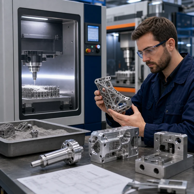
CNC post-processing is often the practical bridge between additive geometry and precision assembly. DMLS may create an internal cooling channel, lightweight lattice, or complex bracket form, while 5-axis machining or precision milling finishes the surfaces that need to mate with other parts.

  • Machine datums first so later inspection has stable references.
  • Leave machining allowance on printed bosses, pads, holes, and sealing faces.
  • Avoid printing final precision holes unless the tolerance is loose.
  • Tap or thread-machine critical threads after printing.
  • Plan fixturing early because organic DMLS shapes can be hard to hold.
  • Use inspection data to confirm both printed and machined zones.

Design Tips for Dense DMLS Parts

A dense DMLS part starts with good design. If the part traps powder, overheats in thick sections, has unsupported overhangs, or leaves no allowance for machining, density alone will not make it successful.

  • Avoid unnecessary thick masses that create thermal gradients and long build times.
  • Use lattice structures only where they serve load, weight, airflow, or heat-transfer goals.
  • Add powder escape paths for internal cavities.
  • Design supports so they can be removed without damaging functional areas.
  • Separate as-printed surfaces from post-machined precision surfaces on the drawing.
  • Define density, porosity, and inspection requirements only where they matter.
  • Confirm whether the part needs heat treatment, HIP, or surface finishing.

Inspection Methods for Dense Metal Printed Parts

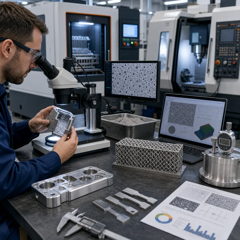
DMLS inspection can include dimensional checks, visual review, microscopy, density measurement, CT scanning, metallography, tensile coupons, hardness testing, and surface roughness measurement. For many projects, inspection should be matched to risk. A concept prototype may only need basic measurement. A pressure part, medical part, or aerospace bracket may need a much stronger quality assurance plan.

Inspection Method What It Checks When It Helps
Dimensional inspection Size, flatness, position, machined features Almost every functional part
CT scanning Internal pores, cracks, trapped powder, channels Complex or critical internal geometry
Metallography Microstructure, fusion quality, pores Process validation and high-risk parts
Tensile coupons Strength, elongation, material response Material qualification and critical builds
Surface roughness testing As-printed or machined surface condition Sealing, fatigue, flow, and cosmetic surfaces

Applications Where Density Matters

Density matters most when a part carries load, sees fatigue, holds pressure, transfers heat, or must pass strict validation. Examples include aerospace brackets, medical implants or instruments, heat exchangers, manifolds, tooling inserts with conformal cooling, lightweight robotic structures, and high-performance prototypes.

For less critical visual prototypes, density may be less important than appearance, geometry, and lead time. In those cases, polymer printing, CNC machining, or rapid prototyping with another process may be more practical.

When to Choose CNC Instead of DMLS

If a part is a simple bracket, plate, shaft, housing, or block with accessible features, CNC machining is usually the stronger first option. It typically offers better surface finish, tighter tolerances, broader material availability, and lower cost for conventional geometry. DMLS becomes more attractive when geometry complexity is doing real work.

For conventional metal parts, compare aluminum CNC machining, stainless steel CNC machining, titanium CNC machining, and other material options before committing to metal additive manufacturing.

How MTSPi Can Support Dense DMLS Projects

MTSPi focuses on CNC machining, rapid prototyping, materials guidance, surface finishing, and inspection support. If a project uses DMLS for complex geometry, MTSPi can help review the post-machined features: datums, holes, threads, sealing areas, pads, tolerances, finish requirements, and inspection needs.

Send your CAD model, drawing, material requirements, expected load case, quantity, post-machining notes, and inspection requirements through the contact page. We can help decide which surfaces should be printed, which should be machined, and where design allowances are needed.

FAQ

Can DMLS parts be as dense as wrought metal?

DMLS parts can reach high density, but equivalence to wrought metal depends on material, process qualification, heat treatment, HIP, orientation, and inspection. Critical applications should not rely on generic claims alone.

What is the biggest risk with DMLS density?

The biggest risk is hidden porosity or lack of fusion in a functional area, especially near loaded surfaces, pressure boundaries, sealing faces, or fatigue-critical regions.

Does HIP remove all porosity?

HIP can reduce or close certain internal pores, but it does not replace proper process control, design review, support strategy, and inspection.

Should DMLS holes be printed or machined?

Loose clearance holes may be printed, but precision holes, threaded holes, reamed holes, and sealing bores are usually better machined after printing.

Is DMLS good for production parts?

DMLS can be used for production when geometry, quantity, material, certification, and inspection requirements justify it. For simple shapes, CNC machining is often more practical.

Can MTSPi machine DMLS printed blanks?

MTSPi can support CNC post-processing planning for printed blanks, including machined datums, holes, threads, sealing surfaces, finishing, and inspection requirements.

Categories
Blog CNC Machining Basics Guides Manufacturing Process Comparisons

Direct Metal Laser Sintering (DMLS): Metal 3D Printing and CNC Post-Processing Guide

Direct Metal Laser Sintering, commonly shortened to DMLS, is a metal 3D printing process used to build complex metal parts directly from digital CAD data. Instead of cutting material away from a billet, DMLS fuses fine metal powder layer by layer with a high-energy laser. The result can be a dense metal part with shapes that would be difficult, expensive, or impossible to make with conventional machining alone.

For engineers sourcing prototypes or low-volume parts, DMLS should not be viewed as a replacement for every CNC machined component. It is a complementary process. The strongest projects use each method where it makes sense: DMLS for design freedom and complex forms, then CNC machining, turning, finishing, and inspection for critical surfaces.

What Is Direct Metal Laser Sintering?

DMLS is a powder-bed fusion process. A thin layer of metal powder is spread across a build platform. A laser traces the cross-section of the part and fuses selected areas. The platform lowers, a new powder layer is applied, and the process repeats until the full part is built. After printing, loose powder is removed and the part is separated from the build plate.

The process is often grouped with metal 3D printing, selective laser melting, and laser powder bed fusion. Naming can vary by machine supplier and material system, but the practical idea is the same: create metal geometry layer by layer from powder and laser energy.

How DMLS Works Step by Step

  • A 3D CAD model is prepared and oriented for printing.
  • Support structures are added where needed to anchor the part and control heat distortion.
  • A thin metal powder layer is spread across the machine bed.
  • The laser fuses the cross-section of the part in that layer.
  • The build platform lowers and the next powder layer is applied.
  • The completed part is cooled, removed from the powder, and cut from the build plate.
  • Post-processing such as heat treatment, support removal, CNC machining, polishing, blasting, or inspection is completed.

DMLS Materials

DMLS is commonly used with metal materials such as stainless steel, aluminum alloys, titanium alloys, cobalt chrome, nickel alloys, maraging steel, and tool steel depending on supplier capability. The right material depends on strength, weight, corrosion resistance, temperature, fatigue, biocompatibility, and finishing requirements. For machined alternatives, compare options in MTSPi’s CNC machining materials library.

Material Family Why It Is Used in DMLS CNC Selection Note
Stainless steel Corrosion resistance and general mechanical strength CNC may be better for simple shafts, fittings, plates, and precision faces
Aluminum alloys Lightweight functional prototypes and aerospace-style parts CNC aluminum is often faster and smoother for conventional geometry
Titanium alloys High strength-to-weight ratio and medical or aerospace applications CNC titanium can finish critical surfaces after printing
Nickel alloys Heat and corrosion resistance Post-machining may be required for mating surfaces and tight features
Tool or maraging steel High strength tooling, inserts, and conformal cooling concepts Heat treatment and final machining must be planned carefully

Advantages of DMLS

  • Can produce complex internal channels, lattice structures, and lightweight forms.
  • Reduces assembly count by combining several parts into one printed component.
  • Useful for functional metal prototypes without hard tooling.
  • Supports design iterations before casting, forging, or machining strategy is finalized.
  • Can create conformal cooling channels, medical structures, aerospace brackets, and custom tooling inserts.

Limitations of DMLS

  • Surface finish is usually rougher than CNC machining unless post-processed.
  • Tolerances may not match precision machining on critical holes, flats, threads, and sealing areas.
  • Support structures can leave marks and require removal.
  • Build orientation affects strength, surface quality, support needs, and dimensional accuracy.
  • Material choices are narrower than conventional CNC stock materials.
  • Simple prismatic or turned parts are often cheaper and faster by CNC machining.

DMLS vs CNC Machining

DMLS and CNC machining solve different problems. DMLS creates geometry by adding material, so it is excellent when the geometry is complex. CNC machining removes material from solid stock, so it is excellent when the part needs accurate surfaces, holes, threads, flatness, repeatability, and a broad material choice.

Decision Point Choose DMLS When Choose CNC Machining When
Geometry Internal channels, lattice structures, organic shapes, topology-optimized parts Prismatic parts, shafts, plates, housings, brackets, pockets, threaded features
Tolerance Moderate tolerance is acceptable or post-machining is planned Tight dimensions, datums, flatness, bore accuracy, and threads are critical
Surface finish As-printed or blasted surface is acceptable Smooth machined, polished, anodized, plated, or sealing surfaces are required
Quantity Complex prototypes or specialized low-volume components Prototypes through production batches with repeatable geometry
Cost Complexity justifies the process Geometry is simple enough to machine efficiently

For conventional metal prototypes, rapid prototyping through CNC machining is often the more practical choice. For complex parts with internal channels or lightweight structures, DMLS may be better first, followed by CNC post-processing.

When DMLS Parts Need CNC Post-Processing

Many DMLS parts are not finished when they leave the printer. Support removal and heat treatment are common, and precision features often need secondary machining. A printed bracket may need CNC-milled mounting faces. A printed manifold may need reamed holes, tapped ports, or machined sealing surfaces. A printed insert may need ground or polished functional areas.

  • Machine flat datum surfaces that locate the part in an assembly.
  • Drill, ream, or bore precision holes after printing.
  • Tap threads instead of relying only on printed thread geometry.
  • Machine sealing surfaces and bearing seats.
  • Use polishing, blasting, or coating to control surface finish.
  • Inspect critical features with gauges, CMM, or optical methods.

Design Rules for DMLS Parts

Designing for DMLS is different from designing for CNC machining. A geometry that prints well may be difficult to inspect or post-machine. A geometry that machines well may not use the full value of additive manufacturing. The best design considers both printing and secondary operations from the beginning.

  • Avoid unnecessary solid mass; use ribs, shells, or lattice only where they support function.
  • Plan support access and removal before approving the design.
  • Add machining allowance on critical faces, holes, and sealing areas.
  • Orient the part to balance accuracy, surface finish, strength direction, and support requirements.
  • Avoid enclosed powder traps unless powder removal is designed into the part.
  • Mark post-machined features clearly on the drawing.
  • Define inspection requirements for functional surfaces rather than over-tolerancing the whole part.

Tolerances and Surface Finish

DMLS tolerances depend on machine, material, part size, orientation, heat treatment, and post-processing. Small details can be impressive, but precision mating features usually need machining. Surface finish is also process-dependent. As-printed metal surfaces often have a granular texture, while machined faces are smoother and more dimensionally controlled.

If the part needs a controlled finish, consider the full process route: print, stress relieve, remove supports, CNC machine, inspect, then apply finishing if needed. For finish options on metal parts, see MTSPi’s surface treatment guide.

Common Applications

DMLS is useful where geometry complexity creates real value. Typical applications include aerospace brackets, lightweight robotic parts, conformal cooling inserts, medical implants or instruments, custom manifolds, heat exchangers, complex housings, and low-volume metal prototypes.

In many of these applications, DMLS and CNC are combined. A lightweight printed shape may still need 5-axis machining to finish complex datum surfaces or angled features. A printed round feature may need turning or grinding for final fit.

Cost Drivers in DMLS

  • Build volume and part height affect machine time.
  • Material powder cost varies significantly by alloy.
  • Support structures add build time and removal labor.
  • Heat treatment, HIP, machining, polishing, and inspection add cost.
  • Poor orientation can increase supports, distortion, and post-processing difficulty.
  • A part designed like a conventional machined block may waste the benefits of DMLS.

How to Decide Between DMLS, CNC, and Hybrid Manufacturing

Start with the function. If the part is a simple plate, bracket, shaft, spacer, or housing with accessible features, CNC machining is usually the first option to quote. If the part has internal flow channels, impossible undercuts, topology-optimized load paths, or a design that combines many parts into one, DMLS becomes more attractive.

For the strongest decision, split the part into functional zones. Which surfaces need precision? Which areas carry load? Which areas only need clearance? Which features can remain as-printed? Which features must be machined after printing? This approach avoids paying for unnecessary precision while protecting the features that actually matter.

How MTSPi Can Support DMLS-Related Projects

MTSPi focuses on custom CNC machining, rapid prototyping, surface finishing, and inspection support. Even when a project starts with metal 3D printing, CNC post-processing may be required to turn the printed blank into a functional assembly-ready part. MTSPi can help review drawings for machined datums, holes, threads, sealing faces, finish requirements, and inspection planning.

If your project is comparing metal 3D printing and machining, send your CAD model, drawing, material requirements, quantity, tolerance notes, and application details through the contact page. We can help identify which features should be printed, which should be CNC machined, and where design changes may reduce risk.

FAQ

What is DMLS used for?

DMLS is used for complex metal prototypes and low-volume parts such as lightweight brackets, manifolds, conformal cooling inserts, medical structures, aerospace components, and custom tooling.

Is DMLS the same as SLS?

They are related powder-bed processes, but SLS is often used for polymers while DMLS refers to metal powder fusion. Naming varies across suppliers, so material and process details should be confirmed.

Are DMLS parts fully dense?

DMLS parts can achieve high density when processed correctly, but final properties depend on material, machine parameters, orientation, heat treatment, and quality control.

Can DMLS make threads?

Threads can sometimes be printed, but functional precision threads are often tapped or machined after printing for better accuracy and strength.

When is CNC machining better than DMLS?

CNC machining is usually better for simple geometry, tight tolerance, smooth finish, broad material selection, and repeatable production at lower cost.

Can MTSPi machine DMLS parts after printing?

MTSPi can support CNC post-processing considerations such as machined faces, holes, threads, datum surfaces, finishing, and inspection planning for metal prototype projects.

Request A Quote

We'll Send You Back with Price Immediately!

DEC 1-31

XMAS SPECEIL

Up to

40% off

Direct Metal Laser Sintering (DMLS): Metal 3D Printing and CNC Post-Processing Guide

We'll Send You Back with Price Immediately!