Categories
Blog Design, Cost & Sourcing Guides Manufacturing Process Comparisons

Sheet Metal Part Design Mistakes: DFM Checklist for Better Parts

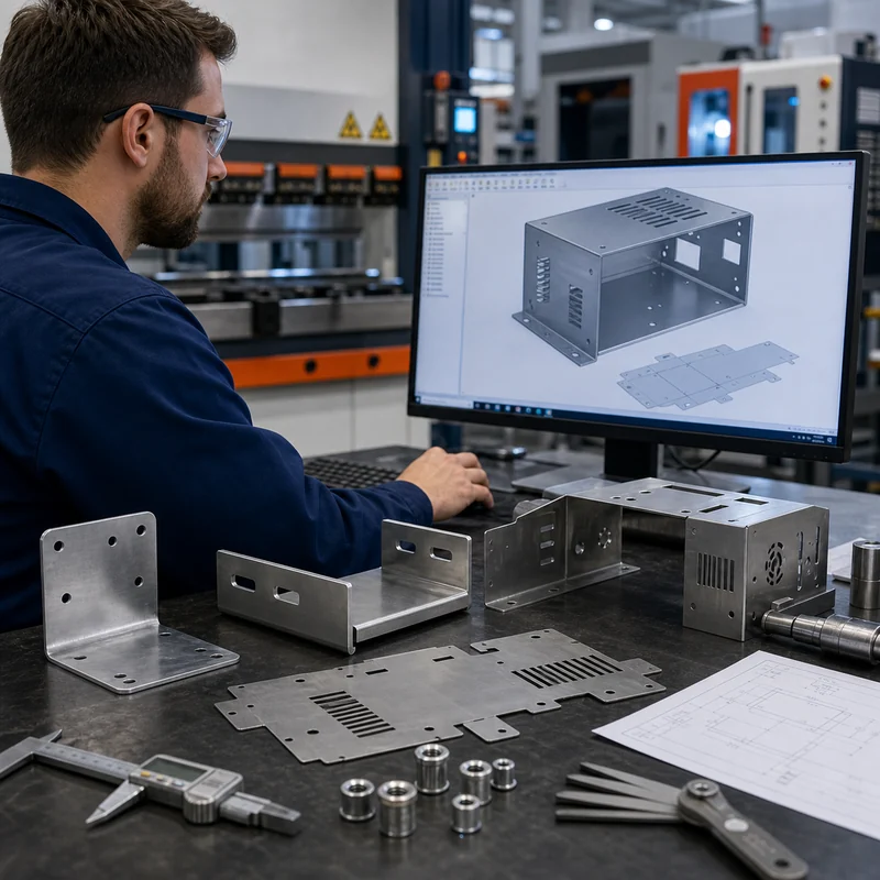
Sheet metal parts look simple on a screen, but small design mistakes can create big problems during laser cutting, bending, hardware insertion, welding, finishing, and assembly. A hole placed too close to a bend may distort. A missing bend relief may tear. A coating may close up a tight slot. A U-shaped channel may flex even though the material looks thick enough.

This guide rewrites the common sheet metal design mistakes into a practical DFM checklist for engineers, product developers, and sourcing teams. It also connects sheet metal decisions with rapid prototyping, CNC machining, material selection, and surface treatment, because many real parts combine fabrication, machining, inserts, finishing, and inspection.

Quick Checklist: Sheet Metal Design Mistakes to Avoid

Mistake What Can Go Wrong Better Design Habit
No true sheet metal model or flat pattern Bends, reliefs, and blank size may be wrong Use CAD sheet metal features and export a clean flat pattern
Holes too close to bends Holes stretch, become oval, or interfere with tooling Keep cutouts away from bend lines and confirm supplier rules
Sharp perpendicular corners Stress concentration, cracking, poor finish, higher tooling risk Use radii and bend relief where the material changes direction
Missing hardware details Wrong PEM nut, standoff, thread, or clearance Specify hardware type, size, material, and installation side
Finish chosen too late Coating affects dimensions, masking, color, or corrosion performance Plan finishing before tolerances are frozen
Wrong material or thickness Part bends too easily, cracks, costs too much, or cannot be formed Choose material by strength, bendability, corrosion, and finish
Weak U-channel or long unsupported flange Part twists, opens, vibrates, or deforms in assembly Add returns, ribs, hems, beads, or thicker material
Welds or fasteners are inaccessible Assembly is slow, inconsistent, or impossible Check tool access, torch access, screw access, and inspection access

Mistake 1: Designing Without Sheet Metal Features

A common issue is modeling the part as a solid block instead of a true sheet metal component. Sheet metal parts must unfold into a flat blank, then bend into the final shape. If the CAD model does not define thickness, bend radius, relief, K-factor, and bend direction, the manufacturer may have to reinterpret the design before quoting or production.

Use sheet metal tools in CAD whenever possible. Confirm that the part can flatten cleanly, that bends are consistent, and that the flat pattern matches the intended manufacturing method. If the part includes machined areas, inserts, or welded elements, mark them separately instead of hiding everything inside a generic 3D model.

Mistake 2: Placing Holes Too Close to Bend Lines

Holes, slots, vents, and cutouts near a bend line can stretch or distort during forming. Round holes may become oval, slots may pull out of shape, and countersinks may become unusable. The problem becomes more visible in thicker material, tighter bend radii, and harder alloys.

  • Move holes away from bend lines when the hole shape must stay accurate.
  • Use bend relief if a cutout must approach a formed edge.
  • Confirm whether holes should be cut before bending or machined after bending.
  • Leave room for tooling, punch clearance, hardware heads, and inspection gauges.

Mistake 3: Using Sharp Corners Where Radii Are Needed

Sharp internal corners create stress concentration and can be difficult to cut, bend, weld, polish, or coat. In sheet metal, sharp corners also increase the chance of tearing around bends or creating burr-heavy edges. A small radius often improves both function and manufacturability.

For laser-cut profiles, corner radii can reduce burr risk and coating build-up. For formed features, realistic bend radii prevent cracking and improve repeatability. If a sharp corner is functional, identify only that area instead of making every corner unnecessarily sharp.

Mistake 4: Forgetting Bend Relief and Flange Rules

Bend relief prevents tearing and unwanted deformation where a bend ends near an edge or another feature. Flanges also need enough length for tooling to grip and form the part. If a flange is too short, the part may not bend consistently or may require special tooling.

Design Area Risk DFM Check
Bend relief Tearing or bulging near bend ends Add relief slots or notches where needed
Minimum flange length Tooling cannot form the bend reliably Check against material thickness and bend tooling
Bend radius Cracking or inaccurate angle Use standard inside radii where possible
Bend sequence Earlier bends block later bends Review whether tooling can reach each bend

Mistake 5: Not Specifying Hardware Correctly

Self-clinching nuts, studs, standoffs, threaded inserts, rivets, weld nuts, and fasteners are common in sheet metal assemblies. If the drawing only says insert nut here, the supplier may not know the required thread, material, installation side, flange clearance, plating compatibility, or pull-out strength.

  • Specify hardware part number or an approved equivalent.
  • Show installation side and orientation clearly.
  • Confirm hole size and sheet thickness range for the hardware.
  • Keep hardware away from bends, edges, and other fasteners unless clearance is verified.
  • Consider plating or coating after hardware insertion if conductivity or masking matters.

Mistake 6: Choosing Finish After the Design Is Finished

Surface treatment should be considered early. Powder coating, anodizing, plating, black oxide, passivation, painting, and polishing all affect cost, lead time, appearance, corrosion resistance, and sometimes dimensions. A coating can close up small holes or slots. Masking may be needed for threads, electrical contact, grounding areas, or bearing surfaces.

If the part combines sheet metal and machined elements, finishing becomes even more important. Review finish requirements with surface treatment planning before locking the drawing.

Mistake 7: Choosing the Wrong Material or Thickness

Material choice controls strength, stiffness, bendability, corrosion resistance, weight, cost, and finish options. Aluminum is lightweight and corrosion resistant but softer than steel. Mild steel is economical and strong but needs corrosion protection. Stainless steel resists corrosion but may cost more and be harder to form. Copper and brass bring electrical, thermal, or cosmetic value but require their own design allowances.

Material Good For Watch Points
Aluminum sheet Lightweight brackets, covers, panels, enclosures Softer threads, bend cracking in some tempers, anodizing allowance
Mild steel Strong economical brackets, frames, fixtures Rust protection required
Stainless steel Corrosion-resistant covers, medical or food equipment, outdoor hardware Higher cost and springback
Copper Electrical and thermal parts Softness, scratching, bend control
Brass Decorative or electrical components Cost, forming limits, finish sensitivity

For broader metal comparison, use the CNC metal machining and materials pages as supporting resources when the part includes both formed and machined features.

Mistake 8: Making U-Channels and Long Flanges Too Weak

U-shaped channels, C-shaped brackets, and long unsupported flanges can look strong in CAD but twist or open under load. The problem is common in enclosures, rails, mounting brackets, and covers. Thin sheet with a long flange may vibrate, oil-can, or deform during assembly.

  • Add return flanges to increase stiffness.
  • Use ribs, beads, gussets, hems, or formed features where allowed.
  • Increase thickness only after checking cost and bend feasibility.
  • Reduce unsupported span when possible.
  • Use spot welds, fasteners, or machined reinforcements when needed.

Mistake 9: Ignoring Welding and Assembly Access

A part can be manufacturable as a single piece but difficult to weld, fasten, inspect, or service. Weld guns, torches, clamps, screwdrivers, rivet tools, and gauges all need access. If access is blocked by a flange or enclosure wall, the assembly may become slow or impossible to build consistently.

Before releasing drawings, review the actual build order. Which bend happens first? When is hardware installed? Can the part be clamped for welding? Can a screw be tightened? Can a gauge reach the feature after assembly? These questions prevent expensive late-stage redesign.

Mistake 10: Treating Every Dimension as Critical

Over-tolerancing sheet metal can raise cost without improving function. Formed parts naturally have more variation than machined parts because bend angle, springback, grain direction, tooling, and material batch affect the result. Critical mating features should be controlled, but non-critical overall dimensions often need more practical tolerances.

If a feature truly needs high precision, consider whether it should be machined after forming or designed as a separate CNC component. MTSPi can support related 3-axis machining, 5-axis machining, and inspection planning for hybrid parts.

A Practical Sheet Metal DFM Workflow

  • Start with function: load, appearance, environment, assembly, and service access.
  • Choose material and thickness before finalizing bends and hardware.
  • Use proper sheet metal CAD features and check the flat pattern.
  • Verify bend radius, bend relief, flange length, and hole-to-bend distance.
  • Specify hardware, threads, inserts, welds, and finish requirements clearly.
  • Review coating thickness, masking, and corrosion protection.
  • Separate critical tolerances from non-critical reference dimensions.
  • Prototype high-risk designs before ordering larger batches.

How MTSPi Helps With Sheet Metal and CNC-Related Parts

MTSPi mainly supports CNC machining, rapid prototyping, materials guidance, finishing, and inspection for custom parts. Many customer projects include sheet metal enclosures, brackets, machined inserts, shafts, plates, and hardware that must fit together. We can review drawings for manufacturability, CNC features, finish planning, assembly risks, and inspection requirements.

For a sheet metal or hybrid CNC project, send your 3D model, flat pattern, 2D drawing, material, thickness, quantity, finish, and hardware notes through the contact page. The earlier DFM feedback happens, the easier it is to avoid expensive design revisions.

FAQ

What is DFM for sheet metal?

DFM for sheet metal means designing parts so they can be cut, bent, formed, finished, assembled, and inspected reliably with practical tooling and tolerances.

Why do holes distort near bends?

Material stretches and compresses during bending. If a hole or slot is too close to the bend line, the forming process can pull it out of shape.

Should sheet metal parts have sharp corners?

Sharp corners should be avoided unless they are functional. Radii reduce stress concentration, improve finishing, and often make cutting and forming more reliable.

When should hardware be specified on the drawing?

Hardware should be specified before quoting and production, including thread size, part number or equivalent, installation side, hole size, material, and finish requirements.

Can sheet metal parts be combined with CNC machined parts?

Yes. Many assemblies combine sheet metal covers or brackets with CNC machined blocks, shafts, spacers, inserts, and precision mounting features.

Can MTSPi review sheet metal designs for manufacturability?

MTSPi can review CNC-related features, materials, finishing, assembly risks, and inspection needs for sheet metal and hybrid custom-part projects.

Categories
Blog CNC Machining Basics Guides Manufacturing Process Comparisons

Direct Metal Laser Sintering (DMLS): Metal 3D Printing and CNC Post-Processing Guide

Direct Metal Laser Sintering, commonly shortened to DMLS, is a metal 3D printing process used to build complex metal parts directly from digital CAD data. Instead of cutting material away from a billet, DMLS fuses fine metal powder layer by layer with a high-energy laser. The result can be a dense metal part with shapes that would be difficult, expensive, or impossible to make with conventional machining alone.

For engineers sourcing prototypes or low-volume parts, DMLS should not be viewed as a replacement for every CNC machined component. It is a complementary process. The strongest projects use each method where it makes sense: DMLS for design freedom and complex forms, then CNC machining, turning, finishing, and inspection for critical surfaces.

What Is Direct Metal Laser Sintering?

DMLS is a powder-bed fusion process. A thin layer of metal powder is spread across a build platform. A laser traces the cross-section of the part and fuses selected areas. The platform lowers, a new powder layer is applied, and the process repeats until the full part is built. After printing, loose powder is removed and the part is separated from the build plate.

The process is often grouped with metal 3D printing, selective laser melting, and laser powder bed fusion. Naming can vary by machine supplier and material system, but the practical idea is the same: create metal geometry layer by layer from powder and laser energy.

How DMLS Works Step by Step

  • A 3D CAD model is prepared and oriented for printing.
  • Support structures are added where needed to anchor the part and control heat distortion.
  • A thin metal powder layer is spread across the machine bed.
  • The laser fuses the cross-section of the part in that layer.
  • The build platform lowers and the next powder layer is applied.
  • The completed part is cooled, removed from the powder, and cut from the build plate.
  • Post-processing such as heat treatment, support removal, CNC machining, polishing, blasting, or inspection is completed.

DMLS Materials

DMLS is commonly used with metal materials such as stainless steel, aluminum alloys, titanium alloys, cobalt chrome, nickel alloys, maraging steel, and tool steel depending on supplier capability. The right material depends on strength, weight, corrosion resistance, temperature, fatigue, biocompatibility, and finishing requirements. For machined alternatives, compare options in MTSPi’s CNC machining materials library.

Material Family Why It Is Used in DMLS CNC Selection Note
Stainless steel Corrosion resistance and general mechanical strength CNC may be better for simple shafts, fittings, plates, and precision faces
Aluminum alloys Lightweight functional prototypes and aerospace-style parts CNC aluminum is often faster and smoother for conventional geometry
Titanium alloys High strength-to-weight ratio and medical or aerospace applications CNC titanium can finish critical surfaces after printing
Nickel alloys Heat and corrosion resistance Post-machining may be required for mating surfaces and tight features
Tool or maraging steel High strength tooling, inserts, and conformal cooling concepts Heat treatment and final machining must be planned carefully

Advantages of DMLS

  • Can produce complex internal channels, lattice structures, and lightweight forms.
  • Reduces assembly count by combining several parts into one printed component.
  • Useful for functional metal prototypes without hard tooling.
  • Supports design iterations before casting, forging, or machining strategy is finalized.
  • Can create conformal cooling channels, medical structures, aerospace brackets, and custom tooling inserts.

Limitations of DMLS

  • Surface finish is usually rougher than CNC machining unless post-processed.
  • Tolerances may not match precision machining on critical holes, flats, threads, and sealing areas.
  • Support structures can leave marks and require removal.
  • Build orientation affects strength, surface quality, support needs, and dimensional accuracy.
  • Material choices are narrower than conventional CNC stock materials.
  • Simple prismatic or turned parts are often cheaper and faster by CNC machining.

DMLS vs CNC Machining

DMLS and CNC machining solve different problems. DMLS creates geometry by adding material, so it is excellent when the geometry is complex. CNC machining removes material from solid stock, so it is excellent when the part needs accurate surfaces, holes, threads, flatness, repeatability, and a broad material choice.

Decision Point Choose DMLS When Choose CNC Machining When
Geometry Internal channels, lattice structures, organic shapes, topology-optimized parts Prismatic parts, shafts, plates, housings, brackets, pockets, threaded features
Tolerance Moderate tolerance is acceptable or post-machining is planned Tight dimensions, datums, flatness, bore accuracy, and threads are critical
Surface finish As-printed or blasted surface is acceptable Smooth machined, polished, anodized, plated, or sealing surfaces are required
Quantity Complex prototypes or specialized low-volume components Prototypes through production batches with repeatable geometry
Cost Complexity justifies the process Geometry is simple enough to machine efficiently

For conventional metal prototypes, rapid prototyping through CNC machining is often the more practical choice. For complex parts with internal channels or lightweight structures, DMLS may be better first, followed by CNC post-processing.

When DMLS Parts Need CNC Post-Processing

Many DMLS parts are not finished when they leave the printer. Support removal and heat treatment are common, and precision features often need secondary machining. A printed bracket may need CNC-milled mounting faces. A printed manifold may need reamed holes, tapped ports, or machined sealing surfaces. A printed insert may need ground or polished functional areas.

  • Machine flat datum surfaces that locate the part in an assembly.
  • Drill, ream, or bore precision holes after printing.
  • Tap threads instead of relying only on printed thread geometry.
  • Machine sealing surfaces and bearing seats.
  • Use polishing, blasting, or coating to control surface finish.
  • Inspect critical features with gauges, CMM, or optical methods.

Design Rules for DMLS Parts

Designing for DMLS is different from designing for CNC machining. A geometry that prints well may be difficult to inspect or post-machine. A geometry that machines well may not use the full value of additive manufacturing. The best design considers both printing and secondary operations from the beginning.

  • Avoid unnecessary solid mass; use ribs, shells, or lattice only where they support function.
  • Plan support access and removal before approving the design.
  • Add machining allowance on critical faces, holes, and sealing areas.
  • Orient the part to balance accuracy, surface finish, strength direction, and support requirements.
  • Avoid enclosed powder traps unless powder removal is designed into the part.
  • Mark post-machined features clearly on the drawing.
  • Define inspection requirements for functional surfaces rather than over-tolerancing the whole part.

Tolerances and Surface Finish

DMLS tolerances depend on machine, material, part size, orientation, heat treatment, and post-processing. Small details can be impressive, but precision mating features usually need machining. Surface finish is also process-dependent. As-printed metal surfaces often have a granular texture, while machined faces are smoother and more dimensionally controlled.

If the part needs a controlled finish, consider the full process route: print, stress relieve, remove supports, CNC machine, inspect, then apply finishing if needed. For finish options on metal parts, see MTSPi’s surface treatment guide.

Common Applications

DMLS is useful where geometry complexity creates real value. Typical applications include aerospace brackets, lightweight robotic parts, conformal cooling inserts, medical implants or instruments, custom manifolds, heat exchangers, complex housings, and low-volume metal prototypes.

In many of these applications, DMLS and CNC are combined. A lightweight printed shape may still need 5-axis machining to finish complex datum surfaces or angled features. A printed round feature may need turning or grinding for final fit.

Cost Drivers in DMLS

  • Build volume and part height affect machine time.
  • Material powder cost varies significantly by alloy.
  • Support structures add build time and removal labor.
  • Heat treatment, HIP, machining, polishing, and inspection add cost.
  • Poor orientation can increase supports, distortion, and post-processing difficulty.
  • A part designed like a conventional machined block may waste the benefits of DMLS.

How to Decide Between DMLS, CNC, and Hybrid Manufacturing

Start with the function. If the part is a simple plate, bracket, shaft, spacer, or housing with accessible features, CNC machining is usually the first option to quote. If the part has internal flow channels, impossible undercuts, topology-optimized load paths, or a design that combines many parts into one, DMLS becomes more attractive.

For the strongest decision, split the part into functional zones. Which surfaces need precision? Which areas carry load? Which areas only need clearance? Which features can remain as-printed? Which features must be machined after printing? This approach avoids paying for unnecessary precision while protecting the features that actually matter.

How MTSPi Can Support DMLS-Related Projects

MTSPi focuses on custom CNC machining, rapid prototyping, surface finishing, and inspection support. Even when a project starts with metal 3D printing, CNC post-processing may be required to turn the printed blank into a functional assembly-ready part. MTSPi can help review drawings for machined datums, holes, threads, sealing faces, finish requirements, and inspection planning.

If your project is comparing metal 3D printing and machining, send your CAD model, drawing, material requirements, quantity, tolerance notes, and application details through the contact page. We can help identify which features should be printed, which should be CNC machined, and where design changes may reduce risk.

FAQ

What is DMLS used for?

DMLS is used for complex metal prototypes and low-volume parts such as lightweight brackets, manifolds, conformal cooling inserts, medical structures, aerospace components, and custom tooling.

Is DMLS the same as SLS?

They are related powder-bed processes, but SLS is often used for polymers while DMLS refers to metal powder fusion. Naming varies across suppliers, so material and process details should be confirmed.

Are DMLS parts fully dense?

DMLS parts can achieve high density when processed correctly, but final properties depend on material, machine parameters, orientation, heat treatment, and quality control.

Can DMLS make threads?

Threads can sometimes be printed, but functional precision threads are often tapped or machined after printing for better accuracy and strength.

When is CNC machining better than DMLS?

CNC machining is usually better for simple geometry, tight tolerance, smooth finish, broad material selection, and repeatable production at lower cost.

Can MTSPi machine DMLS parts after printing?

MTSPi can support CNC post-processing considerations such as machined faces, holes, threads, datum surfaces, finishing, and inspection planning for metal prototype projects.

Categories
Blog Design, Cost & Sourcing Guides

How to Choose the Right Rapid Prototyping Process for Custom Parts

Rapid prototyping is not one single manufacturing method. It is a decision process: choose the fastest, most reliable way to turn a design into a physical part that can be tested, assembled, measured, shown to customers, or prepared for production. The right choice depends on what the prototype must prove, not only on which process is fastest.

For custom parts, the main options include rapid prototyping services, CNC machining, 3D printing, sheet metal fabrication, urethane casting, and prototype tooling. This guide explains how to compare them from an engineering and sourcing point of view, especially when the final product may later require CNC milling, CNC turning, or low-volume production.

Quick Answer: Match the Process to the Question You Need to Answer

Prototype Goal Best Starting Process Why It Works
Check shape, size, and assembly space 3D printing Fast turnaround and low setup cost for complex geometry
Test strength, threads, sealing faces, and real material behavior CNC machining Uses production-grade metals and plastics with tight dimensions
Validate brackets, covers, panels, and enclosures Sheet metal fabrication Matches formed metal behavior, bend radii, holes, and hardware
Review molded-part look and flexible plastic behavior Urethane casting or prototype tooling Useful for soft-touch, colored, or molded-like samples
Prepare for pilot production CNC machining or bridge tooling Supports repeatable batches before full production tooling

What Is Rapid Prototyping?

Rapid prototyping is the practice of making physical parts quickly so a team can learn before committing to expensive tooling, large material purchases, or production schedules. A prototype may be a simple visual model, a fit-check sample, a functional part, an engineering validation unit, or a small batch used for market testing.

The word rapid can be misleading. The goal is not always the shortest lead time. Sometimes the best prototype takes slightly longer because it gives better data. A CNC machined aluminum housing, for example, may be more valuable than a quick printed model if the team needs to test threads, flatness, heat transfer, or sealing surfaces.

The Main Rapid Prototyping Processes

1. CNC Machining

CNC machining removes material from a solid block, plate, rod, or extrusion. It is often the strongest choice when prototypes must use real production materials such as aluminum, stainless steel, brass, copper, titanium, ABS, Delrin, PEEK, or nylon. MTSPi commonly uses this route for precision parts, housings, brackets, shafts, fixtures, and functional prototypes.

  • Best for: functional prototypes, tight tolerances, threads, metal parts, engineering plastic parts, heat sinks, housings, and parts that will later be machined in production.
  • Advantages: real material properties, good surface finish, strong dimensional control, many finish options, and easy transition to low-volume production.
  • Limitations: internal sharp corners require radii, very complex hollow geometry may need design changes, and cost can rise with deep pockets or long machining time.

2. 3D Printing

3D printing builds parts layer by layer. It is useful for quick design iteration, complex shapes, lightweight structures, internal channels, and early fit checks. Common options include FDM, SLA, SLS, MJF, and metal additive manufacturing. Each process has different accuracy, strength, surface finish, and material behavior.

Use 3D printing when geometry speed matters more than final material equivalence. For parts with critical mounting surfaces, threads, bearing fits, or sealing faces, printed prototypes may still need inserts, post-machining, or a later CNC version.

3. Sheet Metal Prototyping

Sheet metal prototyping is ideal for covers, panels, chassis parts, brackets, shields, clips, and electrical enclosures. It can validate flat patterns, bends, hardware positions, PEM inserts, and assembly clearance. If the final product is sheet metal, a printed block model cannot fully replace a bent metal prototype.

  • Best for: brackets, enclosures, mounting plates, protective covers, and formed metal components.
  • Watch points: bend radius, grain direction, minimum flange length, hole-to-bend distance, and finish requirements.

4. Urethane Casting

Urethane casting uses silicone molds to produce small batches of plastic-like parts. It is useful for visual prototypes, sales samples, housings, colored parts, soft-touch components, and designs that need a molded appearance before injection tooling is ready. It is not the same as injection molding, but it can be a practical bridge for presentation and low-volume needs.

5. Prototype Injection Molding and Bridge Tooling

Prototype tooling is used when the team must test molded material, gate marks, shrinkage, living hinges, snap fits, or early production quantities. Tooling costs more than machining or printing, but it gives better information when the final part will be injection molded.

How to Choose the Right Rapid Prototyping Process

A practical process choice starts with the purpose of the prototype. Ask what decision the part must support. If the goal is visual approval, a fast printed or cast prototype may be enough. If the goal is mechanical testing, real material and accurate geometry matter more. If the goal is production planning, repeatability and inspection data become important.

Decision Factor Choose CNC Machining When Choose 3D Printing When Choose Tooling or Casting When
Material behavior The prototype must match aluminum, steel, brass, copper, titanium, or engineering plastic A substitute material is acceptable for early testing Molded plastic behavior or appearance is the main concern
Tolerance Holes, mating faces, threads, and flatness must be controlled Loose fit or visual geometry is acceptable Mold shrinkage and molded fits must be studied
Geometry Features can be accessed by cutting tools Complex internal geometry or organic forms are important Part is designed as a molded component
Quantity One piece to hundreds of parts One piece to small batches Dozens to thousands depending on tool strategy
Surface finish Machined, polished, anodized, plated, or bead blasted finish is required Layered or post-processed finish is acceptable Molded-like cosmetic finish is needed

CNC Machining vs 3D Printing for Rapid Prototypes

CNC machining and 3D printing are often compared because both can produce prototypes without full production tooling. The difference is how close the prototype needs to be to the final part. CNC machining is subtractive, so it starts with a real billet or sheet and produces a part with strong material behavior. 3D printing is additive, so it can produce complex shapes quickly, but layer direction and material substitutes may affect testing.

For example, a printed bracket may confirm shape and assembly clearance, but a machined aluminum CNC machining prototype is better for load testing, thread strength, heat transfer, and final finish review. A printed nylon duct may work for airflow validation, while Delrin CNC machining or nylon machining may be better for sliding wear or dimensional checks.

Cost Drivers in Rapid Prototyping

Prototype cost is controlled by geometry, material, tolerance, finish, quantity, and inspection. A simple part in common aluminum may be affordable by CNC machining. A part with deep pockets, thin walls, many setups, tight GD&T, and cosmetic anodizing will cost more. A printed part with large volume, expensive resin, support removal, and finishing can also become costly.

  • Reduce unnecessary tight tolerances on non-critical features.
  • Use standard material sizes when possible.
  • Avoid very deep narrow pockets unless they are functional.
  • Add radii that match practical cutting tools.
  • Separate cosmetic requirements from functional requirements on drawings.
  • Group similar prototypes to reduce setup and communication time.

Materials for Rapid Prototyping

Material selection should follow the prototype goal. For metal prototypes, aluminum is common because it machines quickly, has good strength-to-weight ratio, and accepts finishes such as anodizing. Stainless steel is chosen for corrosion resistance and strength. Brass and copper are chosen for electrical, thermal, or decorative requirements. Titanium is chosen when strength-to-weight and corrosion resistance matter. You can compare options in the CNC machining materials section.

For plastics, ABS is useful for general housings and prototypes, Delrin/POM is strong for low-friction precision parts, PEEK is used for demanding heat and chemical environments, and nylon is common for wear-resistant mechanical components. When the material is uncertain, the safest route is to explain the working environment and let the manufacturer compare options before quoting.

Surface Finishing for Prototype Parts

A prototype may need more than shape. Surface finish can affect appearance, corrosion resistance, wear, electrical behavior, and customer approval. Common options include bead blasting, anodizing, polishing, black oxide, powder coating, nickel plating, chrome plating, passivation, and painting. For finish selection, see MTSPi’s surface treatment guide.

Do not apply a finish only because it looks good on a sample. Finishing changes lead time, cost, dimensions, masking requirements, and sometimes material behavior. For precision prototypes, confirm whether inspection should happen before or after finishing.

From Prototype to Low-Volume Production

A good prototype should make production easier. If a design will later be CNC machined, use prototype feedback to simplify setups, remove unnecessary tight features, choose better stock size, and confirm inspection points. If a design will later be molded, use prototypes to refine wall thickness, ribs, bosses, draft, texture, and assembly features before tooling.

For small batches, rapid prototyping and custom CNC machining services can often bridge the gap between one-off samples and production tooling. This is useful when the design is still changing, the market is being tested, or annual demand does not justify hard tooling yet.

A Practical Selection Workflow

  • Define the prototype purpose: visual, fit, functional, regulatory, customer sample, or pilot batch.
  • List critical features: tolerances, threads, flatness, sealing faces, surface finish, and loaded areas.
  • Choose material based on the test, not only on availability.
  • Select a process that answers the key risk with the least wasted time.
  • Review DFM feedback before ordering, especially for thin walls, deep pockets, undercuts, and finishing.
  • Use inspection results and test feedback to revise the design before the next iteration.

When to Work With MTSPi

MTSPi is a good fit when your prototype needs real engineering material, controlled tolerances, practical DFM feedback, and a path toward repeatable low-volume supply. We can support CNC milled parts, turned parts, plastic prototypes, metal prototypes, surface finishing, and inspection planning for custom components.

To start a project, send your 3D model, 2D drawing, material preference, required quantity, finish, tolerance notes, and target application through the contact page. If you are still comparing processes, MTSPi can help decide whether CNC machining, 3D printing, sheet metal, or another prototyping route makes the most sense.

FAQ

What is the fastest rapid prototyping process?

For simple geometry and early concept checks, 3D printing is often fastest. For real metal or engineering plastic parts with precise dimensions, CNC machining may provide more useful results even if the lead time is slightly longer.

Is CNC machining good for rapid prototyping?

Yes. CNC machining is one of the best rapid prototyping methods when the part needs final-grade material, accurate holes, threads, flatness, surface finish, or functional testing close to production conditions.

What is the cheapest way to make a prototype?

The cheapest route depends on geometry and purpose. A simple printed model may be lowest cost for visual review, while a CNC machined part can be cheaper overall if it prevents failed tests, wrong material assumptions, or redesign later.

Can rapid prototypes be used as end-use parts?

Yes, especially when made by CNC machining or suitable sheet metal fabrication. Many low-volume end-use parts are produced through prototype-style workflows when tooling is not economical.

How do I send files for a rapid prototype quote?

Send a 3D CAD model, 2D drawing if tolerances matter, material choice, quantity, finish, and application notes. You can submit them through MTSPi’s contact page.

Categories
Guides

How to Read Engineering Drawings for Machining Quotes and Part Quality

How to read engineering drawings is a practical question because the word is used in design reviews, RFQs, supplier audits, cost discussions, and quality reports. In manufacturing, it usually describes controlled material removal from metal or plastic stock to create a part with defined shape, dimensions, surface condition, and functional features. For buyers, the useful answer is not only the dictionary definition; it is how the process affects material choice, tolerance, lead time, finish, inspection, and supplier communication.

This guide combines common top-page coverage with CNC buyer details that are often missing: drawing requirements, process selection, cost drivers, inspection evidence, and realistic questions to ask before placing an order with MTSPi CNC / MEITESI.

Quick Answer

How to read engineering drawings refers to a manufacturing subject connected to cutting, shaping, or removing material with controlled tools. In CNC work, the main decision is how to turn a drawing or model into a repeatable part without overpaying for unnecessary tolerance, finish, or setup complexity. A buyer should start with the part function, then define material, quantity, critical dimensions, finish, and inspection requirements.

When a part needs milled faces, pockets, slots, holes, or 3D profiles, a process-specific review can help match the geometry to a practical route. When the part includes round features, shafts, threads, bushings, or sleeves, turning may be more efficient than forcing the work into a milling setup.

Key Takeaways

  • How to read engineering drawings should be understood through part function, not only a short definition.
  • The same term can mean different things in engineering, purchasing, shop-floor planning, and inspection.
  • Material grade, tolerance, surface finish, and batch quantity often matter more than the process name.
  • A clear 2D drawing is still important even when a 3D model is available.
  • The best supplier questions focus on risk: workholding, tool access, burrs, finish, measurement, and repeatability.

Definition and Core Meaning

Most leading educational pages explain how to read engineering drawings with a simple idea: controlled shaping of material into a desired part. That definition is useful, but it is incomplete for real sourcing work. A buyer also needs to know what will be held, where the cutting forces go, which surfaces are cosmetic, which dimensions control assembly, and what evidence proves the finished part is acceptable.

In a CNC project, the definition becomes more concrete. The process starts with a drawing, model, material, stock size, tools, fixtures, and inspection plan. If any of these are unclear, the quote may look fast but the project can still run into rework. MTSPi CNC reviews those details through drawing and model preparation before the machining route is finalized.

A useful way to think about the term is this: machining is not just cutting material away. It is a chain of decisions that includes programming, setup, tool selection, clamping, roughing, finishing, deburring, surface treatment, inspection, packaging, and communication. Each step can change cost and quality.

Question Simple answer Buyer detail that matters
What is being made? A part from raw material. The drawing should identify datums, threads, finish, tolerances, and critical surfaces.
How is material removed? By cutting tools or controlled energy. Tool access, chip control, heat, and workholding decide whether the process is stable.
What affects price? Machine time and material. Setup count, tolerance, finish, inspection, burr control, and quantity are often just as important.
How is quality confirmed? By inspection. Inspection should match the drawing risk with the right gauge, report, or sampling plan.

Main Process Categories

The most common process categories include milling, turning, drilling, boring, tapping, reaming, grinding, EDM, and finishing operations. Educational pages often list these as separate processes, but real parts often use several of them. A housing may need milling, drilling, tapping, deburring, bead blasting, and anodizing. A shaft may need turning, threading, grooving, polishing, and runout inspection.

Milling removes material with rotating cutters and is common for flat faces, pockets, slots, holes, and complex surfaces. Buyers can review CNC milling support when a part has prismatic geometry or multiple machined faces. Turning rotates the workpiece and is usually efficient for round parts, shafts, bushings, threaded pins, sleeves, and spacers; for these parts, CNC turning support may be the better starting point.

Drilling, boring, tapping, and reaming are hole-making or hole-finishing operations. They look simple on a drawing, but hole depth, thread engagement, position tolerance, burr direction, and access from one side or both sides can affect machining risk. Deep holes and small threaded holes deserve special attention before quoting.

A strong process choice also considers the order of operations. A hole drilled before milling may move slightly after material is removed around it. A thin wall roughed too aggressively may release stress and lose flatness. A cosmetic surface finished too early may be damaged during later clamping. These sequencing details are rarely visible in a simple definition, yet they are often the difference between a clean first batch and repeated correction.

Process Best suited for Common risk
Milling Flat faces, slots, pockets, 3D contours, hole patterns Long tool reach, vibration, internal corner radius, thin wall movement
Turning Shafts, bushings, sleeves, pins, threaded round parts Runout, concentricity, surface finish, slender-part deflection
Drilling and tapping Holes, threads, fastener locations Broken taps, wrong thread depth, burrs, poor position control
Grinding or fine finishing Tight surfaces and improved roughness Extra cost, measurement demand, and possible lead time increase

Materials and Manufacturing Considerations

Material choice changes nearly every part of how to read engineering drawings. Aluminum usually machines quickly and accepts many finishes, but thin walls may deform and cosmetic surfaces need protection. Stainless steel is strong and corrosion resistant, but it can work harden and increase tool wear. Brass cuts cleanly, copper needs careful burr and heat control, titanium demands conservative cutting and cooling, and engineering plastics need heat management and gentle workholding.

For metal projects, metal machining choices gives a useful way to compare alloy behavior before the RFQ is finalized. For projects where aluminum is likely, buyers should think about 6061, 7075, anodizing, flatness, and cost. Stainless steel buyers should pay attention to 304 versus 316, burr behavior, passivation, and the cost impact of tight tolerances.

Material is not only a performance choice. It is also a supply-chain choice. Availability, stock shape, minimum order size, certificate requirements, and substitute-grade permission can all affect quote speed. Buyers should state whether equivalent materials are allowed or whether the listed grade is mandatory.

Material Why buyers choose it Machining note
Aluminum Light weight, good machinability, many finish options Thin walls and cosmetic faces need careful sequence and handling.
Stainless steel Corrosion resistance, strength, clean appearance Tool wear, burrs, and work hardening can raise cost.
Brass or copper Conductivity, appearance, thread quality, fittings Copper can be gummy; brass is easier but alloy choice still matters.
Engineering plastics Weight reduction, insulation, wear behavior Heat, clamping, and burr control are important.

Cost, Tolerance, and Surface Finish Factors

Cost is often misunderstood because buyers compare only the unit price. A quote also reflects programming, setup, material preparation, fixture design, tool life, cutting time, deburring, finish, inspection, packaging, and delivery risk. A low quote may hide missing assumptions, while a high quote may include inspection or finish work that another supplier ignored.

Tolerances should protect function rather than decorate every feature. Tight dimensions on noncritical surfaces add cost without improving performance. A better approach is to mark critical features clearly and allow standard tolerances elsewhere. MTSPi CNC can review machining cost reduction checks when buyers want to reduce price without weakening the part.

Surface finish also changes the process. A visible aluminum panel may need careful tool paths, deburring, polishing, bead blasting, or anodizing. A hidden bracket may only need safe edges and functional holes. Surface expectations should be discussed before machining, especially when a post-machining finish will be applied after cutting.

Tolerance and finish should also be separated by purpose. A sealing face, bearing seat, threaded hole, and decorative cover do not fail in the same way. A sealing face may need flatness and surface roughness control. A bearing seat may need diameter, roundness, and runout. A visible cover may need consistent texture and protected edges. A hidden mounting plate may only need hole position and deburred edges. This distinction helps buyers spend money where it protects function.

Factor Why it changes the quote How to control it
Tight tolerance Requires slower cutting, stable setup, and more inspection Apply it only to functional features.
Small batch Setup cost is spread over fewer parts Combine parts or request quantity breaks.
Complex finish Adds handling, protection, and rework risk Define visible and hidden surfaces separately.
Incomplete drawing Supplier must guess or ask repeated questions Send drawing, model, material, finish, and quantity together.

Design and Drawing Notes for Better Results

Good design makes the important features reliable. Internal corners should allow realistic cutter radius. Deep pockets should allow tool access. Thin walls need enough stiffness for cutting and finishing. Threads should have clear depth and class. Holes should show whether they are blind, through, tapped, reamed, or counterbored.

A 3D model gives geometry, but the 2D drawing gives manufacturing intent. It should identify datums, tolerances, surface roughness, thread callouts, finish requirements, revision level, and inspection notes. Without this, the supplier may produce the shape correctly but miss the real acceptance standard.

For prototype work, prototype machining review helps confirm fit and function before the design moves to a production order. For repeated small batches, fixture notes, approved samples, and inspection records should be kept with the job so later orders do not restart the learning process.

Common Mistakes to Avoid

  • Using a broad term without explaining the part’s function or assembly risk.
  • Sending only a model when threads, finish, tolerances, and critical features are needed.
  • Specifying tight tolerances on every dimension instead of only where fit or performance requires them.
  • Leaving surface finish until after the machining process is already fixed.
  • Comparing supplier quotes without checking whether material, finish, inspection, and packing assumptions match.
  • Approving a prototype without recording what changed before low-volume production.

Supplier and Quotation Checklist

A good RFQ package helps suppliers answer quickly and accurately. It should include the model, drawing, material, quantity, finish, target lead time, inspection requirement, and any special packaging need. If the part is used with another component, include a short note about the mating feature or failure concern.

A capable supplier should explain the process route, not only state that the part can be made. Ask about workholding, tool access, burr control, inspection, and finish sequence. The answer should be specific enough that an engineer can see how the part will be controlled before shipment.

RFQ item What to provide Why it helps
3D model STEP or other usable CAD format Supports programming and geometry review.
2D drawing Tolerances, datums, threads, finish, revision Shows manufacturing intent and acceptance rules.
Material Grade, temper, certificate need, substitute permission Controls performance, cost, and availability.
Quantity Prototype and production breaks Helps choose fixture and process strategy.
Inspection Critical dimensions and report needs Prevents disputes after delivery.

How to Use This Information in a Real RFQ

After reading a definition or comparison, buyers should turn the information into a short RFQ note. The note can be simple: part function, material preference, expected quantity, important mating features, visible surfaces, and delivery target. This small addition helps the supplier understand why certain features matter and where standard manufacturing variation is acceptable.

For example, instead of asking only for a price, a buyer can write that two bores locate bearings, the top face is visible after assembly, the threaded holes need repeated installation, and the first order is for functional testing. That kind of note guides process planning, inspection priority, and packaging protection without making the project more complicated.

Specific Notes for How to Read Engineering Drawings for Machining Quotes and Part Quality

For the topic how to read engineering drawings, the most useful article is one that begins with the general definition but quickly moves into practical manufacturing choices. The front-page results commonly explain the concept well, yet they often leave buyers without enough detail about drawings, tolerance, cost, finishing, inspection, and supplier communication.

The better approach is to connect the concept to part features. If the part has milled pockets, use milling logic. If it has round geometry, evaluate turning. If it needs a smooth visible finish, plan surface treatment early. If it has tight functional dimensions, decide the inspection method before accepting the quote.

This is why MTSPi CNC / MEITESI treats every request as a connected manufacturing problem rather than a single-word process label. A clear drawing, suitable material, realistic tolerance, and measurable quality standard make the finished part easier to quote, easier to produce, and easier to approve.

Practical Buyer Scenario

Consider a buyer who searches for how to read engineering drawings because a new project has moved from concept to sourcing. The drawing shows a metal housing with two bearing bores, four mounting holes, a visible top surface, and a note calling for black finish. A basic educational explanation may help the buyer understand the term, but it will not answer the real purchasing questions: which faces are datums, whether the bores need inspection reports, whether the finish changes dimensions, and how the supplier will protect the visible surface during shipping.

In that situation, the buyer should not ask only whether the supplier can machine the part. A better request is to ask for a review of stock material, setup count, bore measurement, edge break, surface finish route, and packaging. If the housing is still being tested, prototype machining review can help confirm geometry before repeat orders. If the order will move into small batches, the buyer should ask which setup details can be reused and which dimensions need routine reporting.

This scenario shows why information articles should lead into real manufacturing decisions. The reader may begin with a broad question, but the project succeeds only when the definition becomes a drawing, a process route, a material order, a controlled finish, and an inspection method. That is the bridge between learning a term and buying usable parts.

Conclusion

How to Read Engineering Drawings for Machining Quotes and Part Quality should be understood as a practical manufacturing topic, not just a short definition. Buyers should use the concept to make better decisions about process selection, materials, tolerances, finish, cost, inspection, and supplier communication. With a clear RFQ package and a supplier that explains the route before production, MTSPi CNC / MEITESI can help turn general manufacturing knowledge into reliable machined parts.

FAQ

What does how to read engineering drawings mean in manufacturing?

It generally refers to a controlled way of shaping material, often by removing material with tools or machine processes. In CNC work, the meaning also includes programming, setup, workholding, finishing, and inspection.

What information should I send for a CNC quote?

Send a 3D model, 2D drawing, material grade, quantity, finish requirement, critical dimensions, thread notes, and any assembly concerns.

Is CNC machining always the best process?

No. It is excellent for precision parts, prototypes, low-volume production, metal components, and many plastic parts, but casting, forming, molding, or fabrication may suit some designs better.

Why do machining costs vary so much?

Costs vary because material, setup count, tolerance, finish, inspection, tooling, batch size, and lead time can change the real work behind the same-looking part.

How can buyers reduce machining risk?

Clarify drawings, mark critical features, choose suitable materials, avoid unnecessary tight tolerances, define finish expectations, and request inspection evidence that matches the part function.

Categories
Guides

Screw Thread Types: Complete Guide to Metric, UNC, UNF, NPT, BSP, Acme, and CNC Thread Design

Quick answer: The most common screw thread types include metric threads, UNC, UNF, NPT, BSP, Acme, trapezoidal, buttress, and special custom threads. Metric, UNC, and UNF are mainly used for fastening. NPT and BSP are used for pipe connections. Acme and trapezoidal threads are used for power transmission and motion. CNC drawings should clearly define thread size, pitch, class, depth, and inspection method.

What Is a Screw Thread?

A screw thread is a helical ridge or groove formed on the inside or outside of a cylindrical feature. Threads allow parts to fasten, adjust, seal, transmit motion, or carry load. In CNC machining, threads can be tapped, thread milled, single-point turned, die cut, rolled, or formed depending on material, geometry, quantity, and accuracy requirements.

Thread problems are common because thread standards look similar but are not always interchangeable. A metric M6 thread is not the same as a 1/4-20 UNC thread. A straight BSPP pipe thread is not the same as a tapered NPT thread. A drawing must remove this ambiguity before machining begins.

Main Screw Thread Types

Thread type Typical use How it is specified CNC machining note
Metric thread General international fastening M size and pitch, such as M6 x 1.0 Very common for global mechanical assemblies
UNC General inch fasteners Diameter and threads per inch, such as 1/4-20 Coarse pitch, practical for many materials
UNF Fine inch fasteners Diameter and TPI, such as 1/4-28 Finer pitch, often used where adjustment or vibration resistance matters
NPT Tapered pipe sealing Nominal pipe size and TPI Requires taper and sealing consideration
BSPP / BSPT Pipe connections in many international systems British Standard Pipe callout Confirm parallel or tapered form before machining
Acme / trapezoidal Lead screws and motion systems Diameter, pitch, and form Used for load and movement, not ordinary fastening
Buttress thread High load in one direction Special thread form and dimensions Requires careful drawing and tool planning

Metric Threads

Metric threads are common worldwide. A metric callout such as M8 x 1.25 means the nominal diameter is 8 mm and the pitch is 1.25 mm. Coarse pitch metric threads are common for general fastening, while fine pitch threads can be useful when there is limited engagement length, a need for finer adjustment, or vibration concerns.

For CNC machined parts, metric threads should include depth for blind holes, through-hole notation where relevant, and tolerance class when fit is important. If the part will be anodized, plated, or coated, thread fit may need masking or post-finish checking.

UNC and UNF Threads

UNC means Unified National Coarse, while UNF means Unified National Fine. UNC threads are common for general inch fasteners and are usually more tolerant of dirt, plating, and softer materials. UNF threads have finer pitch and can provide more precise adjustment or better resistance to loosening in some assemblies.

UNC and UNF are not interchangeable. They may have the same nominal diameter but different pitch. A 1/4-20 fastener will not fit a 1/4-28 hole correctly. Drawings should always show the full thread callout.

NPT, BSP, and Pipe Threads

Pipe threads are used for fluid or gas connections, but they are not all the same. NPT is a tapered pipe thread commonly used in North America. BSPP is parallel, while BSPT is tapered. The sealing method may depend on thread interference, sealant, O-rings, washers, or mating hardware.

Pipe thread features require careful planning because the effective depth, gauge position, sealing requirement, and orientation may matter. For CNC buyers, it is safer to provide the mating fitting standard or sample if there is any uncertainty.

Internal vs External Threads

Internal threads are inside holes. They are commonly produced by tapping or thread milling. External threads are on outside diameters and are often produced by turning, thread milling, rolling, or dies. Internal blind holes need extra care because taps and thread mills require clearance at the bottom.

Tapping vs Thread Milling vs Single-Point Threading

Method Best use Advantages Limitations
Tapping Standard internal threads Fast and economical Broken taps can be costly, less flexible for special threads
Thread milling Large threads, hard materials, blind holes, special sizes Flexible and lower cutting force Usually slower than tapping
Single-point turning External or internal lathe threads Good control for turned parts Best suited to round components
Thread rolling High-volume external threads Strong thread form, no chips Requires suitable material and tooling

CNC Thread Design Checklist

  • Use standard thread sizes whenever possible.
  • Show thread size, pitch, class, and depth clearly.
  • Identify blind holes and through holes.
  • Leave tool clearance near shoulders and hole bottoms.
  • Do not specify unnecessary deep threads.
  • Confirm thread fit after anodizing, plating, or coating.
  • Use inserts when plastic or thin walls cannot provide enough thread strength.
  • Use go/no-go gauges for standard thread inspection.

Related CNC Machining Considerations

Threaded features often appear in CNC milled brackets, housings, plates, covers, and fixtures. They also appear in CNC turned fittings, shafts, sleeves, pins, and bushings. If the thread is close to a cosmetic surface, planned finishing from the surface treatment stage can prevent fit issues.

FAQ

What are the most common screw thread types?

Metric, UNC, UNF, NPT, BSP, and Acme are among the most common thread types used in mechanical design and CNC machining.

What is the difference between metric and UNC threads?

Metric threads are specified in millimeters and pitch. UNC threads are inch-based and specified by nominal diameter and threads per inch.

Is NPT the same as BSP?

No. NPT and BSP have different forms and standards. They should not be treated as interchangeable unless the connection is specifically designed for compatibility.

Should I use tapping or thread milling?

Tapping is usually faster for standard internal threads. Thread milling is useful for large threads, hard materials, blind holes, and special thread control.

How do CNC shops inspect threads?

Standard internal and external threads are commonly checked with go/no-go gauges. Critical features may also require depth checks, CMM location checks, or mating part tests.

Need threaded CNC parts?

Send the full thread callout, material, finish, and drawing. MTSPi can review tap, thread milling, turning, and inspection requirements.

Contact MTSPi for thread machining support

Conclusion

Screw thread selection affects assembly strength, sealing, cost, inspection, and production risk. Clear thread standards, practical depth, suitable machining method, and correct gauges help CNC machined parts fit correctly the first time.

Categories
Guides

Metric Thread Chart: Sizes, Pitch, Tap Drills, and CNC Machining Notes

Quick answer: A metric thread chart lists thread sizes such as M3, M4, M5, M6, M8, and M10 with pitch and tap drill information. CNC buyers use it to define threaded holes, fastener fit, thread depth, and inspection requirements.

Metric Thread Chart Guide

Metric threads are common in international mechanical designs. The drawing should show diameter, pitch, thread depth, blind or through condition, and tolerance class when fit is important.

Key Points for Buyers and Engineers

Topic What to know Practical impact
Thread size M6 means nominal 6 mm diameter Defines fastener size.
Pitch Distance between thread peaks Controls coarse or fine thread behavior.
Tap drill Hole size before tapping Affects thread engagement and tool life.
Thread depth Usable full thread length Important for strength and assembly.
Tolerance class Fit requirement such as 6H Helps inspection and compatibility.

How This Affects CNC Machined Parts

Metric threads are made by tapping or thread milling. For complex parts, thread planning should connect to CNC milling, turning, finishing, and inspection requirements.

Design and Purchasing Checklist

  • Always specify pitch for non-default threads.
  • Avoid unnecessary deep blind threads.
  • Leave tool clearance at hole bottoms.
  • Confirm coating effects on thread fit.
  • Use gauges for critical threaded holes.

Related MTSPi Resources

FAQ

What does M6 x 1 mean?

It means a metric thread with 6 mm nominal diameter and 1 mm pitch.

Is metric thread pitch always required?

It is best to include it, especially when using fine pitch or non-standard thread choices.

Can metric threads be CNC machined?

Yes. They can be tapped, thread milled, or turned depending on internal/external thread type.

Need help with metric thread design?

Send drawings, material, quantity, finish, tolerance notes, and application requirements. MTSPi can review manufacturability before quoting.

Contact MTSPi for engineering and quote support

Practical Buyer Notes

Metric thread chart pages should go beyond listing M sizes. They should explain pitch, tap drill size, thread depth, tolerance class, blind-hole clearance, and finish effects.

Users often search metric charts while preparing drawings. The page should help them avoid incomplete callouts such as only saying M6 without pitch, depth, class, or through/blind condition.

How to Evaluate This Topic on a Real Drawing

Decision point Recommended approach Why it matters
Thread callout Include diameter and pitch Avoids wrong tap or fastener
Blind hole Define thread depth and bottom clearance Prevents tool and assembly issues
Finish Consider plating or anodizing thickness Can affect thread fit
Inspection Use correct go/no-go gauges Confirms functional thread acceptance

Common Mistakes to Avoid

  • Leaving pitch out of fine metric thread callouts.
  • Specifying thread depth deeper than necessary.
  • Ignoring coating buildup in threaded holes.
  • Confusing tap drill size with final thread size.

Recommended MTSPi Review Workflow

MTSPi should review metric threads along with hole machining and finish requirements. Thread depth, material, and coating can change the best machining method.

  1. Confirm the part function, operating environment, and assembly risk.
  2. Review material, process, tolerance, surface finish, and inspection requirements together.
  3. Separate critical features from general dimensions so cost is not wasted on non-functional details.
  4. Use related resources such as CNC materials, surface treatment, and quality assurance to complete the specification.
  5. Send the final drawing package to MTSPi for quote review before production.

What to Send for a Faster Quote

Send complete thread callouts, hole depth, blind or through condition, material, finish, tolerance class, and mating fastener details.

  • 3D CAD file and 2D drawing with revision number.
  • Material grade or acceptable alternatives.
  • Quantity, delivery target, and whether samples are required first.
  • Critical dimensions, thread callouts, finish notes, and inspection requirements.
  • Application notes when the part is used in heat, moisture, wear, vibration, or visible assemblies.

Deeper Engineering Notes

For metric thread selection, the strongest page is not just a definition. It should help a buyer decide what information belongs on the drawing, what questions to ask a supplier, and which details affect cost, quality, and delivery. In real RFQ work, the important details are usually pitch, tap drill, thread depth, tolerance class, blind-hole clearance, coating thickness, and gauge checks. These details decide whether the supplier can quote confidently or has to return with repeated questions.

The common risk is writing only M6 or M8 on a drawing without pitch, depth, or fit expectations. That risk can make the content look complete on the surface but weak in a real manufacturing situation. A stronger specification connects the topic to material behavior, machine access, tolerance control, finishing, and inspection before the order is released.

Example Specification Review

Review area Question to answer Good specification practice
Function What does this feature or part need to do? Describe the load, fit, motion, appearance, sealing, or assembly requirement.
Material Is the selected material suitable for the environment? Confirm strength, heat, corrosion, wear, chemical exposure, and cosmetic needs.
Geometry Can the feature be reached by standard tools? Review depth, corner radius, wall thickness, tool clearance, and setup direction.
Tolerance Which dimensions are truly critical? Use tight tolerances only where function requires them and keep general dimensions practical.
Verification How will acceptance be checked? Define gauges, CMM checks, roughness measurement, thread inspection, or visual standards when needed.

How This Page Should Support Ranking

This topic can attract both beginner searches and buyer searches. The beginner wants a clear answer; the buyer wants enough detail to make a manufacturing decision. A page has a better chance to rank when it answers the simple question first, then adds examples, process limits, design notes, comparison tables, and practical next steps.

That is also why internal links should be helpful rather than forced. A reader should naturally move from this page to a process page, material page, surface finish page, inspection page, or quote page only when that next step solves a real question.

Conclusion

A metric thread chart helps define fastener features, but drawings should still include pitch, depth, tolerance, and inspection requirements for reliable CNC machining.

Categories
Guides

Thread Size Chart: Metric, UNC, UNF, Tap Drill, and CNC Design Guidance

Quick answer: A thread size chart helps identify thread diameter, pitch, tap drill size, and fastener compatibility. It is useful for CNC drawings because threaded holes and external threads must be clear before machining and inspection.

Thread Size Chart for CNC Buyers

Thread mistakes are common because metric, UNC, UNF, NPT, BSP, and special forms use different naming systems. A clear drawing prevents wrong taps, wrong pitch, weak thread engagement, and assembly problems.

Key Points for Buyers and Engineers

Topic What to know Practical impact
Metric M size and pitch M6 x 1.0, M8 x 1.25.
UNC Unified coarse inch thread General inch fasteners.
UNF Unified fine inch thread Finer pitch, controlled fit.
Pipe thread NPT, BSPP, BSPT Sealing and pipe connection requirements.
Special thread Acme, trapezoidal, buttress Motion or load-specific designs.

How This Affects CNC Machined Parts

Threaded features may be made during milling, turning, tapping, or thread milling. Inspection should use the correct gauges and drawing notes.

Design and Purchasing Checklist

  • Do not rely only on a hole diameter; specify the thread standard.
  • Show thread depth and whether the hole is blind or through.
  • Confirm class of fit when assembly is critical.
  • Account for plating or coating on threaded parts.
  • Use standard thread sizes when possible.

Related MTSPi Resources

FAQ

What information should a thread callout include?

It should include thread size, pitch or TPI, class, depth, and any special fit or finish requirements.

What is tap drill size?

It is the hole size made before cutting an internal thread.

Are UNC and UNF interchangeable?

No. They use different pitches and should not be mixed unless the assembly is designed for it.

Need help with thread size review?

Send drawings, material, quantity, finish, tolerance notes, and application requirements. MTSPi can review manufacturability before quoting.

Contact MTSPi for engineering and quote support

Practical Buyer Notes

Thread size chart pages rank better when they explain how charts are used in real machining drawings. Metric, UNC, UNF, NPT, and BSP callouts require different information.

The page should reduce buyer mistakes by explaining pitch, TPI, tap drill, thread depth, tolerance class, internal vs external threads, and how finishing affects fit.

How to Evaluate This Topic on a Real Drawing

Decision point Recommended approach Why it matters
Metric Use M size plus pitch Example: M6 x 1.0
UNC/UNF Use inch diameter plus TPI Example: 1/4-20 or 1/4-28
Pipe thread Confirm NPT, BSPP, or BSPT Sealing method differs
Special thread Provide full drawing and mating part Avoids assumptions about form and fit

Common Mistakes to Avoid

  • Mixing metric and inch fasteners.
  • Assuming UNC and UNF are interchangeable.
  • Not giving thread depth for blind holes.
  • Ignoring inspection gauges for production threads.

Recommended MTSPi Review Workflow

MTSPi should use thread chart content to guide readers from reference data to manufacturable drawing notes. The final drawing must define the thread clearly enough for machining and inspection.

  1. Confirm the part function, operating environment, and assembly risk.
  2. Review material, process, tolerance, surface finish, and inspection requirements together.
  3. Separate critical features from general dimensions so cost is not wasted on non-functional details.
  4. Use related resources such as CNC materials, surface treatment, and quality assurance to complete the specification.
  5. Send the final drawing package to MTSPi for quote review before production.

What to Send for a Faster Quote

Send thread standard, size, pitch or TPI, depth, class, material, finish, and mating hardware if the assembly is critical.

  • 3D CAD file and 2D drawing with revision number.
  • Material grade or acceptable alternatives.
  • Quantity, delivery target, and whether samples are required first.
  • Critical dimensions, thread callouts, finish notes, and inspection requirements.
  • Application notes when the part is used in heat, moisture, wear, vibration, or visible assemblies.

Deeper Engineering Notes

For thread size selection, the strongest page is not just a definition. It should help a buyer decide what information belongs on the drawing, what questions to ask a supplier, and which details affect cost, quality, and delivery. In real RFQ work, the important details are usually metric, UNC, UNF, NPT, BSP, tap drill size, thread depth, and mating hardware. These details decide whether the supplier can quote confidently or has to return with repeated questions.

The common risk is mixing standards or assuming similar-looking thread sizes are interchangeable. That risk can make the content look complete on the surface but weak in a real manufacturing situation. A stronger specification connects the topic to material behavior, machine access, tolerance control, finishing, and inspection before the order is released.

Example Specification Review

Review area Question to answer Good specification practice
Function What does this feature or part need to do? Describe the load, fit, motion, appearance, sealing, or assembly requirement.
Material Is the selected material suitable for the environment? Confirm strength, heat, corrosion, wear, chemical exposure, and cosmetic needs.
Geometry Can the feature be reached by standard tools? Review depth, corner radius, wall thickness, tool clearance, and setup direction.
Tolerance Which dimensions are truly critical? Use tight tolerances only where function requires them and keep general dimensions practical.
Verification How will acceptance be checked? Define gauges, CMM checks, roughness measurement, thread inspection, or visual standards when needed.

How This Page Should Support Ranking

This topic can attract both beginner searches and buyer searches. The beginner wants a clear answer; the buyer wants enough detail to make a manufacturing decision. A page has a better chance to rank when it answers the simple question first, then adds examples, process limits, design notes, comparison tables, and practical next steps.

That is also why internal links should be helpful rather than forced. A reader should naturally move from this page to a process page, material page, surface finish page, inspection page, or quote page only when that next step solves a real question.

Conclusion

Thread charts are helpful, but CNC suppliers still need complete thread callouts. Clear thread notes reduce rework and assembly risk.

Categories
Guides

Hole Tolerance Chart: Fits, Clearances, Machining Methods, and Inspection

Quick answer: A hole tolerance chart helps define how much a hole diameter can vary for clearance, location, slip fit, press fit, dowel fit, or bearing fit. Precision holes usually need boring, reaming, or careful inspection instead of drilling alone.

Hole Tolerance Chart and Design Notes

Hole tolerances matter because holes often control assembly. A clearance hole can be loose, but a dowel hole, bearing seat, or alignment bore may require much tighter control.

Key Points for Buyers and Engineers

Topic What to know Practical impact
Clearance hole Allows screw or bolt passage Usually less demanding.
Dowel hole Locates parts accurately Often needs reaming and positional control.
Press fit Interference with mating part Requires tight diameter and material review.
Bearing bore Supports rotating or seated components Needs roundness, diameter, and finish control.
Threaded hole Accepts fasteners Needs tap size, depth, and thread gauge checks.

How This Affects CNC Machined Parts

Holes can be drilled, bored, reamed, tapped, or thread milled. For complex patterns, connect tolerances with inspection planning and datum control.

Design and Purchasing Checklist

  • Use tight tolerances only on functional holes.
  • Specify datum references for hole position.
  • Do not expect drilled holes to behave like reamed holes.
  • Confirm fit with mating components.
  • Define inspection tools for critical holes.

Related MTSPi Resources

FAQ

What is a normal hole tolerance?

It depends on function. Clearance holes can be looser, while dowel holes, bearing bores, and press fits need tighter tolerances.

Is drilling enough for tight holes?

Usually not. Tight holes may need boring or reaming.

How are hole tolerances inspected?

Common tools include pin gauges, bore gauges, CMM, thread gauges, and depth gauges.

Need help with hole tolerance review?

Send drawings, material, quantity, finish, tolerance notes, and application requirements. MTSPi can review manufacturability before quoting.

Contact MTSPi for engineering and quote support

Practical Buyer Notes

Hole tolerance chart pages should explain fit intent, not just dimensions. Clearance holes, dowel holes, bearing bores, press fits, tapped holes, and fluid passages have different tolerance needs.

This page should connect hole tolerance to process choice. Drilling, boring, reaming, and CMM inspection are not interchangeable; each provides a different level of size, position, straightness, and finish control.

How to Evaluate This Topic on a Real Drawing

Decision point Recommended approach Why it matters
Clearance fit Use practical tolerance Allows fastener passage without extra cost
Dowel fit Use reaming and position tolerance Controls alignment
Bearing bore Control diameter, roundness, and finish Supports rotating or seated parts
Press fit Define interference and material pairing Avoids cracked parts or loose assemblies

Common Mistakes to Avoid

  • Using tight hole tolerances without explaining fit purpose.
  • Expecting drill-only holes to meet reamed-hole requirements.
  • Ignoring positional tolerance for hole patterns.
  • Not defining inspection method for critical bores.

Recommended MTSPi Review Workflow

MTSPi should classify each hole by function before quoting. Critical holes may need boring, reaming, special gauges, or CMM checks, while simple clearance holes can stay economical.

  1. Confirm the part function, operating environment, and assembly risk.
  2. Review material, process, tolerance, surface finish, and inspection requirements together.
  3. Separate critical features from general dimensions so cost is not wasted on non-functional details.
  4. Use related resources such as CNC materials, surface treatment, and quality assurance to complete the specification.
  5. Send the final drawing package to MTSPi for quote review before production.

What to Send for a Faster Quote

Send hole diameter, tolerance, position requirement, depth, thread callout, mating part details, and whether inspection reporting is required.

  • 3D CAD file and 2D drawing with revision number.
  • Material grade or acceptable alternatives.
  • Quantity, delivery target, and whether samples are required first.
  • Critical dimensions, thread callouts, finish notes, and inspection requirements.
  • Application notes when the part is used in heat, moisture, wear, vibration, or visible assemblies.

Deeper Engineering Notes

For hole tolerance selection, the strongest page is not just a definition. It should help a buyer decide what information belongs on the drawing, what questions to ask a supplier, and which details affect cost, quality, and delivery. In real RFQ work, the important details are usually clearance holes, dowel holes, bearing bores, press fits, true position, and measurement method. These details decide whether the supplier can quote confidently or has to return with repeated questions.

The common risk is tightening every hole instead of matching tolerance to function. That risk can make the content look complete on the surface but weak in a real manufacturing situation. A stronger specification connects the topic to material behavior, machine access, tolerance control, finishing, and inspection before the order is released.

Example Specification Review

Review area Question to answer Good specification practice
Function What does this feature or part need to do? Describe the load, fit, motion, appearance, sealing, or assembly requirement.
Material Is the selected material suitable for the environment? Confirm strength, heat, corrosion, wear, chemical exposure, and cosmetic needs.
Geometry Can the feature be reached by standard tools? Review depth, corner radius, wall thickness, tool clearance, and setup direction.
Tolerance Which dimensions are truly critical? Use tight tolerances only where function requires them and keep general dimensions practical.
Verification How will acceptance be checked? Define gauges, CMM checks, roughness measurement, thread inspection, or visual standards when needed.

How This Page Should Support Ranking

This topic can attract both beginner searches and buyer searches. The beginner wants a clear answer; the buyer wants enough detail to make a manufacturing decision. A page has a better chance to rank when it answers the simple question first, then adds examples, process limits, design notes, comparison tables, and practical next steps.

That is also why internal links should be helpful rather than forced. A reader should naturally move from this page to a process page, material page, surface finish page, inspection page, or quote page only when that next step solves a real question.

Conclusion

Hole tolerance should match the assembly function. Clear callouts for diameter, position, depth, and inspection help CNC suppliers make reliable parts.

Categories
Guides

GD&T Basics: Datums, Symbols, Tolerances, and Machined Parts

Gd&t basics is a practical question because the word is used in design reviews, RFQs, supplier audits, cost discussions, and quality reports. In manufacturing, it usually describes controlled material removal from metal or plastic stock to create a part with defined shape, dimensions, surface condition, and functional features. For buyers, the useful answer is not only the dictionary definition; it is how the process affects material choice, tolerance, lead time, finish, inspection, and supplier communication.

This guide combines common top-page coverage with CNC buyer details that are often missing: drawing requirements, process selection, cost drivers, inspection evidence, and realistic questions to ask before placing an order with MTSPi CNC / MEITESI.

Quick Answer

Gd&t basics refers to a manufacturing subject connected to cutting, shaping, or removing material with controlled tools. In CNC work, the main decision is how to turn a drawing or model into a repeatable part without overpaying for unnecessary tolerance, finish, or setup complexity. A buyer should start with the part function, then define material, quantity, critical dimensions, finish, and inspection requirements.

When a part needs milled faces, pockets, slots, holes, or 3D profiles, a process-specific review can help match the geometry to a practical route. When the part includes round features, shafts, threads, bushings, or sleeves, turning may be more efficient than forcing the work into a milling setup.

Key Takeaways

  • Gd&t basics should be understood through part function, not only a short definition.
  • The same term can mean different things in engineering, purchasing, shop-floor planning, and inspection.
  • Material grade, tolerance, surface finish, and batch quantity often matter more than the process name.
  • A clear 2D drawing is still important even when a 3D model is available.
  • The best supplier questions focus on risk: workholding, tool access, burrs, finish, measurement, and repeatability.

Definition and Core Meaning

Most leading educational pages explain GD&T basics with a simple idea: controlled shaping of material into a desired part. That definition is useful, but it is incomplete for real sourcing work. A buyer also needs to know what will be held, where the cutting forces go, which surfaces are cosmetic, which dimensions control assembly, and what evidence proves the finished part is acceptable.

In a CNC project, the definition becomes more concrete. The process starts with a drawing, model, material, stock size, tools, fixtures, and inspection plan. If any of these are unclear, the quote may look fast but the project can still run into rework. MTSPi CNC reviews those details through drawing and model preparation before the machining route is finalized.

A useful way to think about the term is this: machining is not just cutting material away. It is a chain of decisions that includes programming, setup, tool selection, clamping, roughing, finishing, deburring, surface treatment, inspection, packaging, and communication. Each step can change cost and quality.

Question Simple answer Buyer detail that matters
What is being made? A part from raw material. The drawing should identify datums, threads, finish, tolerances, and critical surfaces.
How is material removed? By cutting tools or controlled energy. Tool access, chip control, heat, and workholding decide whether the process is stable.
What affects price? Machine time and material. Setup count, tolerance, finish, inspection, burr control, and quantity are often just as important.
How is quality confirmed? By inspection. Inspection should match the drawing risk with the right gauge, report, or sampling plan.

Main Process Categories

The most common process categories include milling, turning, drilling, boring, tapping, reaming, grinding, EDM, and finishing operations. Educational pages often list these as separate processes, but real parts often use several of them. A housing may need milling, drilling, tapping, deburring, bead blasting, and anodizing. A shaft may need turning, threading, grooving, polishing, and runout inspection.

Milling removes material with rotating cutters and is common for flat faces, pockets, slots, holes, and complex surfaces. Buyers can review CNC milling support when a part has prismatic geometry or multiple machined faces. Turning rotates the workpiece and is usually efficient for round parts, shafts, bushings, threaded pins, sleeves, and spacers; for these parts, CNC turning support may be the better starting point.

Drilling, boring, tapping, and reaming are hole-making or hole-finishing operations. They look simple on a drawing, but hole depth, thread engagement, position tolerance, burr direction, and access from one side or both sides can affect machining risk. Deep holes and small threaded holes deserve special attention before quoting.

A strong process choice also considers the order of operations. A hole drilled before milling may move slightly after material is removed around it. A thin wall roughed too aggressively may release stress and lose flatness. A cosmetic surface finished too early may be damaged during later clamping. These sequencing details are rarely visible in a simple definition, yet they are often the difference between a clean first batch and repeated correction.

Process Best suited for Common risk
Milling Flat faces, slots, pockets, 3D contours, hole patterns Long tool reach, vibration, internal corner radius, thin wall movement
Turning Shafts, bushings, sleeves, pins, threaded round parts Runout, concentricity, surface finish, slender-part deflection
Drilling and tapping Holes, threads, fastener locations Broken taps, wrong thread depth, burrs, poor position control
Grinding or fine finishing Tight surfaces and improved roughness Extra cost, measurement demand, and possible lead time increase

Materials and Manufacturing Considerations

Material choice changes nearly every part of GD&T basics. Aluminum usually machines quickly and accepts many finishes, but thin walls may deform and cosmetic surfaces need protection. Stainless steel is strong and corrosion resistant, but it can work harden and increase tool wear. Brass cuts cleanly, copper needs careful burr and heat control, titanium demands conservative cutting and cooling, and engineering plastics need heat management and gentle workholding.

For metal projects, metal machining choices gives a useful way to compare alloy behavior before the RFQ is finalized. For projects where aluminum is likely, buyers should think about 6061, 7075, anodizing, flatness, and cost. Stainless steel buyers should pay attention to 304 versus 316, burr behavior, passivation, and the cost impact of tight tolerances.

Material is not only a performance choice. It is also a supply-chain choice. Availability, stock shape, minimum order size, certificate requirements, and substitute-grade permission can all affect quote speed. Buyers should state whether equivalent materials are allowed or whether the listed grade is mandatory.

Material Why buyers choose it Machining note
Aluminum Light weight, good machinability, many finish options Thin walls and cosmetic faces need careful sequence and handling.
Stainless steel Corrosion resistance, strength, clean appearance Tool wear, burrs, and work hardening can raise cost.
Brass or copper Conductivity, appearance, thread quality, fittings Copper can be gummy; brass is easier but alloy choice still matters.
Engineering plastics Weight reduction, insulation, wear behavior Heat, clamping, and burr control are important.

Cost, Tolerance, and Surface Finish Factors

Cost is often misunderstood because buyers compare only the unit price. A quote also reflects programming, setup, material preparation, fixture design, tool life, cutting time, deburring, finish, inspection, packaging, and delivery risk. A low quote may hide missing assumptions, while a high quote may include inspection or finish work that another supplier ignored.

Tolerances should protect function rather than decorate every feature. Tight dimensions on noncritical surfaces add cost without improving performance. A better approach is to mark critical features clearly and allow standard tolerances elsewhere. MTSPi CNC can review machining cost reduction checks when buyers want to reduce price without weakening the part.

Surface finish also changes the process. A visible aluminum panel may need careful tool paths, deburring, polishing, bead blasting, or anodizing. A hidden bracket may only need safe edges and functional holes. Surface expectations should be discussed before machining, especially when a post-machining finish will be applied after cutting.

Tolerance and finish should also be separated by purpose. A sealing face, bearing seat, threaded hole, and decorative cover do not fail in the same way. A sealing face may need flatness and surface roughness control. A bearing seat may need diameter, roundness, and runout. A visible cover may need consistent texture and protected edges. A hidden mounting plate may only need hole position and deburred edges. This distinction helps buyers spend money where it protects function.

Factor Why it changes the quote How to control it
Tight tolerance Requires slower cutting, stable setup, and more inspection Apply it only to functional features.
Small batch Setup cost is spread over fewer parts Combine parts or request quantity breaks.
Complex finish Adds handling, protection, and rework risk Define visible and hidden surfaces separately.
Incomplete drawing Supplier must guess or ask repeated questions Send drawing, model, material, finish, and quantity together.

Design and Drawing Notes for Better Results

Good design makes the important features reliable. Internal corners should allow realistic cutter radius. Deep pockets should allow tool access. Thin walls need enough stiffness for cutting and finishing. Threads should have clear depth and class. Holes should show whether they are blind, through, tapped, reamed, or counterbored.

A 3D model gives geometry, but the 2D drawing gives manufacturing intent. It should identify datums, tolerances, surface roughness, thread callouts, finish requirements, revision level, and inspection notes. Without this, the supplier may produce the shape correctly but miss the real acceptance standard.

For prototype work, prototype machining review helps confirm fit and function before the design moves to a production order. For repeated small batches, fixture notes, approved samples, and inspection records should be kept with the job so later orders do not restart the learning process.

Common Mistakes to Avoid

  • Using a broad term without explaining the part’s function or assembly risk.
  • Sending only a model when threads, finish, tolerances, and critical features are needed.
  • Specifying tight tolerances on every dimension instead of only where fit or performance requires them.
  • Leaving surface finish until after the machining process is already fixed.
  • Comparing supplier quotes without checking whether material, finish, inspection, and packing assumptions match.
  • Approving a prototype without recording what changed before low-volume production.

Supplier and Quotation Checklist

A good RFQ package helps suppliers answer quickly and accurately. It should include the model, drawing, material, quantity, finish, target lead time, inspection requirement, and any special packaging need. If the part is used with another component, include a short note about the mating feature or failure concern.

A capable supplier should explain the process route, not only state that the part can be made. Ask about workholding, tool access, burr control, inspection, and finish sequence. The answer should be specific enough that an engineer can see how the part will be controlled before shipment.

RFQ item What to provide Why it helps
3D model STEP or other usable CAD format Supports programming and geometry review.
2D drawing Tolerances, datums, threads, finish, revision Shows manufacturing intent and acceptance rules.
Material Grade, temper, certificate need, substitute permission Controls performance, cost, and availability.
Quantity Prototype and production breaks Helps choose fixture and process strategy.
Inspection Critical dimensions and report needs Prevents disputes after delivery.

How to Use This Information in a Real RFQ

After reading a definition or comparison, buyers should turn the information into a short RFQ note. The note can be simple: part function, material preference, expected quantity, important mating features, visible surfaces, and delivery target. This small addition helps the supplier understand why certain features matter and where standard manufacturing variation is acceptable.

For example, instead of asking only for a price, a buyer can write that two bores locate bearings, the top face is visible after assembly, the threaded holes need repeated installation, and the first order is for functional testing. That kind of note guides process planning, inspection priority, and packaging protection without making the project more complicated.

Specific Notes for GD&T Basics: Datums, Symbols, Tolerances, and Machined Parts

For the topic GD&T basics, the most useful article is one that begins with the general definition but quickly moves into practical manufacturing choices. The front-page results commonly explain the concept well, yet they often leave buyers without enough detail about drawings, tolerance, cost, finishing, inspection, and supplier communication.

The better approach is to connect the concept to part features. If the part has milled pockets, use milling logic. If it has round geometry, evaluate turning. If it needs a smooth visible finish, plan surface treatment early. If it has tight functional dimensions, decide the inspection method before accepting the quote.

This is why MTSPi CNC / MEITESI treats every request as a connected manufacturing problem rather than a single-word process label. A clear drawing, suitable material, realistic tolerance, and measurable quality standard make the finished part easier to quote, easier to produce, and easier to approve.

Practical Buyer Scenario

Consider a buyer who searches for GD&T basics because a new project has moved from concept to sourcing. The drawing shows a metal housing with two bearing bores, four mounting holes, a visible top surface, and a note calling for black finish. A basic educational explanation may help the buyer understand the term, but it will not answer the real purchasing questions: which faces are datums, whether the bores need inspection reports, whether the finish changes dimensions, and how the supplier will protect the visible surface during shipping.

In that situation, the buyer should not ask only whether the supplier can machine the part. A better request is to ask for a review of stock material, setup count, bore measurement, edge break, surface finish route, and packaging. If the housing is still being tested, prototype machining review can help confirm geometry before repeat orders. If the order will move into small batches, the buyer should ask which setup details can be reused and which dimensions need routine reporting.

This scenario shows why information articles should lead into real manufacturing decisions. The reader may begin with a broad question, but the project succeeds only when the definition becomes a drawing, a process route, a material order, a controlled finish, and an inspection method. That is the bridge between learning a term and buying usable parts.

Conclusion

GD&T Basics: Datums, Symbols, Tolerances, and Machined Parts should be understood as a practical manufacturing topic, not just a short definition. Buyers should use the concept to make better decisions about process selection, materials, tolerances, finish, cost, inspection, and supplier communication. With a clear RFQ package and a supplier that explains the route before production, MTSPi CNC / MEITESI can help turn general manufacturing knowledge into reliable machined parts.

FAQ

What does GD&T basics mean in manufacturing?

It generally refers to a controlled way of shaping material, often by removing material with tools or machine processes. In CNC work, the meaning also includes programming, setup, workholding, finishing, and inspection.

What information should I send for a CNC quote?

Send a 3D model, 2D drawing, material grade, quantity, finish requirement, critical dimensions, thread notes, and any assembly concerns.

Is CNC machining always the best process?

No. It is excellent for precision parts, prototypes, low-volume production, metal components, and many plastic parts, but casting, forming, molding, or fabrication may suit some designs better.

Why do machining costs vary so much?

Costs vary because material, setup count, tolerance, finish, inspection, tooling, batch size, and lead time can change the real work behind the same-looking part.

How can buyers reduce machining risk?

Clarify drawings, mark critical features, choose suitable materials, avoid unnecessary tight tolerances, define finish expectations, and request inspection evidence that matches the part function.

Categories
Guides

Tolerance in Engineering Drawing: Limits, Fits, Cost, and Inspection

Tolerance in engineering drawing is a practical question because the word is used in design reviews, RFQs, supplier audits, cost discussions, and quality reports. In manufacturing, it usually describes controlled material removal from metal or plastic stock to create a part with defined shape, dimensions, surface condition, and functional features. For buyers, the useful answer is not only the dictionary definition; it is how the process affects material choice, tolerance, lead time, finish, inspection, and supplier communication.

This guide combines common top-page coverage with CNC buyer details that are often missing: drawing requirements, process selection, cost drivers, inspection evidence, and realistic questions to ask before placing an order with MTSPi CNC / MEITESI.

Quick Answer

Tolerance in engineering drawing refers to a manufacturing subject connected to cutting, shaping, or removing material with controlled tools. In CNC work, the main decision is how to turn a drawing or model into a repeatable part without overpaying for unnecessary tolerance, finish, or setup complexity. A buyer should start with the part function, then define material, quantity, critical dimensions, finish, and inspection requirements.

When a part needs milled faces, pockets, slots, holes, or 3D profiles, a process-specific review can help match the geometry to a practical route. When the part includes round features, shafts, threads, bushings, or sleeves, turning may be more efficient than forcing the work into a milling setup.

Key Takeaways

  • Tolerance in engineering drawing should be understood through part function, not only a short definition.
  • The same term can mean different things in engineering, purchasing, shop-floor planning, and inspection.
  • Material grade, tolerance, surface finish, and batch quantity often matter more than the process name.
  • A clear 2D drawing is still important even when a 3D model is available.
  • The best supplier questions focus on risk: workholding, tool access, burrs, finish, measurement, and repeatability.

Definition and Core Meaning

Most leading educational pages explain tolerance in engineering drawing with a simple idea: controlled shaping of material into a desired part. That definition is useful, but it is incomplete for real sourcing work. A buyer also needs to know what will be held, where the cutting forces go, which surfaces are cosmetic, which dimensions control assembly, and what evidence proves the finished part is acceptable.

In a CNC project, the definition becomes more concrete. The process starts with a drawing, model, material, stock size, tools, fixtures, and inspection plan. If any of these are unclear, the quote may look fast but the project can still run into rework. MTSPi CNC reviews those details through drawing and model preparation before the machining route is finalized.

A useful way to think about the term is this: machining is not just cutting material away. It is a chain of decisions that includes programming, setup, tool selection, clamping, roughing, finishing, deburring, surface treatment, inspection, packaging, and communication. Each step can change cost and quality.

Question Simple answer Buyer detail that matters
What is being made? A part from raw material. The drawing should identify datums, threads, finish, tolerances, and critical surfaces.
How is material removed? By cutting tools or controlled energy. Tool access, chip control, heat, and workholding decide whether the process is stable.
What affects price? Machine time and material. Setup count, tolerance, finish, inspection, burr control, and quantity are often just as important.
How is quality confirmed? By inspection. Inspection should match the drawing risk with the right gauge, report, or sampling plan.

Main Process Categories

The most common process categories include milling, turning, drilling, boring, tapping, reaming, grinding, EDM, and finishing operations. Educational pages often list these as separate processes, but real parts often use several of them. A housing may need milling, drilling, tapping, deburring, bead blasting, and anodizing. A shaft may need turning, threading, grooving, polishing, and runout inspection.

Milling removes material with rotating cutters and is common for flat faces, pockets, slots, holes, and complex surfaces. Buyers can review CNC milling support when a part has prismatic geometry or multiple machined faces. Turning rotates the workpiece and is usually efficient for round parts, shafts, bushings, threaded pins, sleeves, and spacers; for these parts, CNC turning support may be the better starting point.

Drilling, boring, tapping, and reaming are hole-making or hole-finishing operations. They look simple on a drawing, but hole depth, thread engagement, position tolerance, burr direction, and access from one side or both sides can affect machining risk. Deep holes and small threaded holes deserve special attention before quoting.

A strong process choice also considers the order of operations. A hole drilled before milling may move slightly after material is removed around it. A thin wall roughed too aggressively may release stress and lose flatness. A cosmetic surface finished too early may be damaged during later clamping. These sequencing details are rarely visible in a simple definition, yet they are often the difference between a clean first batch and repeated correction.

Process Best suited for Common risk
Milling Flat faces, slots, pockets, 3D contours, hole patterns Long tool reach, vibration, internal corner radius, thin wall movement
Turning Shafts, bushings, sleeves, pins, threaded round parts Runout, concentricity, surface finish, slender-part deflection
Drilling and tapping Holes, threads, fastener locations Broken taps, wrong thread depth, burrs, poor position control
Grinding or fine finishing Tight surfaces and improved roughness Extra cost, measurement demand, and possible lead time increase

Materials and Manufacturing Considerations

Material choice changes nearly every part of tolerance in engineering drawing. Aluminum usually machines quickly and accepts many finishes, but thin walls may deform and cosmetic surfaces need protection. Stainless steel is strong and corrosion resistant, but it can work harden and increase tool wear. Brass cuts cleanly, copper needs careful burr and heat control, titanium demands conservative cutting and cooling, and engineering plastics need heat management and gentle workholding.

For metal projects, metal machining choices gives a useful way to compare alloy behavior before the RFQ is finalized. For projects where aluminum is likely, buyers should think about 6061, 7075, anodizing, flatness, and cost. Stainless steel buyers should pay attention to 304 versus 316, burr behavior, passivation, and the cost impact of tight tolerances.

Material is not only a performance choice. It is also a supply-chain choice. Availability, stock shape, minimum order size, certificate requirements, and substitute-grade permission can all affect quote speed. Buyers should state whether equivalent materials are allowed or whether the listed grade is mandatory.

Material Why buyers choose it Machining note
Aluminum Light weight, good machinability, many finish options Thin walls and cosmetic faces need careful sequence and handling.
Stainless steel Corrosion resistance, strength, clean appearance Tool wear, burrs, and work hardening can raise cost.
Brass or copper Conductivity, appearance, thread quality, fittings Copper can be gummy; brass is easier but alloy choice still matters.
Engineering plastics Weight reduction, insulation, wear behavior Heat, clamping, and burr control are important.

Cost, Tolerance, and Surface Finish Factors

Cost is often misunderstood because buyers compare only the unit price. A quote also reflects programming, setup, material preparation, fixture design, tool life, cutting time, deburring, finish, inspection, packaging, and delivery risk. A low quote may hide missing assumptions, while a high quote may include inspection or finish work that another supplier ignored.

Tolerances should protect function rather than decorate every feature. Tight dimensions on noncritical surfaces add cost without improving performance. A better approach is to mark critical features clearly and allow standard tolerances elsewhere. MTSPi CNC can review machining cost reduction checks when buyers want to reduce price without weakening the part.

Surface finish also changes the process. A visible aluminum panel may need careful tool paths, deburring, polishing, bead blasting, or anodizing. A hidden bracket may only need safe edges and functional holes. Surface expectations should be discussed before machining, especially when a post-machining finish will be applied after cutting.

Tolerance and finish should also be separated by purpose. A sealing face, bearing seat, threaded hole, and decorative cover do not fail in the same way. A sealing face may need flatness and surface roughness control. A bearing seat may need diameter, roundness, and runout. A visible cover may need consistent texture and protected edges. A hidden mounting plate may only need hole position and deburred edges. This distinction helps buyers spend money where it protects function.

Factor Why it changes the quote How to control it
Tight tolerance Requires slower cutting, stable setup, and more inspection Apply it only to functional features.
Small batch Setup cost is spread over fewer parts Combine parts or request quantity breaks.
Complex finish Adds handling, protection, and rework risk Define visible and hidden surfaces separately.
Incomplete drawing Supplier must guess or ask repeated questions Send drawing, model, material, finish, and quantity together.

Design and Drawing Notes for Better Results

Good design makes the important features reliable. Internal corners should allow realistic cutter radius. Deep pockets should allow tool access. Thin walls need enough stiffness for cutting and finishing. Threads should have clear depth and class. Holes should show whether they are blind, through, tapped, reamed, or counterbored.

A 3D model gives geometry, but the 2D drawing gives manufacturing intent. It should identify datums, tolerances, surface roughness, thread callouts, finish requirements, revision level, and inspection notes. Without this, the supplier may produce the shape correctly but miss the real acceptance standard.

For prototype work, prototype machining review helps confirm fit and function before the design moves to a production order. For repeated small batches, fixture notes, approved samples, and inspection records should be kept with the job so later orders do not restart the learning process.

Common Mistakes to Avoid

  • Using a broad term without explaining the part’s function or assembly risk.
  • Sending only a model when threads, finish, tolerances, and critical features are needed.
  • Specifying tight tolerances on every dimension instead of only where fit or performance requires them.
  • Leaving surface finish until after the machining process is already fixed.
  • Comparing supplier quotes without checking whether material, finish, inspection, and packing assumptions match.
  • Approving a prototype without recording what changed before low-volume production.

Supplier and Quotation Checklist

A good RFQ package helps suppliers answer quickly and accurately. It should include the model, drawing, material, quantity, finish, target lead time, inspection requirement, and any special packaging need. If the part is used with another component, include a short note about the mating feature or failure concern.

A capable supplier should explain the process route, not only state that the part can be made. Ask about workholding, tool access, burr control, inspection, and finish sequence. The answer should be specific enough that an engineer can see how the part will be controlled before shipment.

RFQ item What to provide Why it helps
3D model STEP or other usable CAD format Supports programming and geometry review.
2D drawing Tolerances, datums, threads, finish, revision Shows manufacturing intent and acceptance rules.
Material Grade, temper, certificate need, substitute permission Controls performance, cost, and availability.
Quantity Prototype and production breaks Helps choose fixture and process strategy.
Inspection Critical dimensions and report needs Prevents disputes after delivery.

How to Use This Information in a Real RFQ

After reading a definition or comparison, buyers should turn the information into a short RFQ note. The note can be simple: part function, material preference, expected quantity, important mating features, visible surfaces, and delivery target. This small addition helps the supplier understand why certain features matter and where standard manufacturing variation is acceptable.

For example, instead of asking only for a price, a buyer can write that two bores locate bearings, the top face is visible after assembly, the threaded holes need repeated installation, and the first order is for functional testing. That kind of note guides process planning, inspection priority, and packaging protection without making the project more complicated.

Specific Notes for Tolerance in Engineering Drawing: Limits, Fits, Cost, and Inspection

For the topic tolerance in engineering drawing, the most useful article is one that begins with the general definition but quickly moves into practical manufacturing choices. The front-page results commonly explain the concept well, yet they often leave buyers without enough detail about drawings, tolerance, cost, finishing, inspection, and supplier communication.

The better approach is to connect the concept to part features. If the part has milled pockets, use milling logic. If it has round geometry, evaluate turning. If it needs a smooth visible finish, plan surface treatment early. If it has tight functional dimensions, decide the inspection method before accepting the quote.

This is why MTSPi CNC / MEITESI treats every request as a connected manufacturing problem rather than a single-word process label. A clear drawing, suitable material, realistic tolerance, and measurable quality standard make the finished part easier to quote, easier to produce, and easier to approve.

Practical Buyer Scenario

Consider a buyer who searches for tolerance in engineering drawing because a new project has moved from concept to sourcing. The drawing shows a metal housing with two bearing bores, four mounting holes, a visible top surface, and a note calling for black finish. A basic educational explanation may help the buyer understand the term, but it will not answer the real purchasing questions: which faces are datums, whether the bores need inspection reports, whether the finish changes dimensions, and how the supplier will protect the visible surface during shipping.

In that situation, the buyer should not ask only whether the supplier can machine the part. A better request is to ask for a review of stock material, setup count, bore measurement, edge break, surface finish route, and packaging. If the housing is still being tested, prototype machining review can help confirm geometry before repeat orders. If the order will move into small batches, the buyer should ask which setup details can be reused and which dimensions need routine reporting.

This scenario shows why information articles should lead into real manufacturing decisions. The reader may begin with a broad question, but the project succeeds only when the definition becomes a drawing, a process route, a material order, a controlled finish, and an inspection method. That is the bridge between learning a term and buying usable parts.

Conclusion

Tolerance in Engineering Drawing: Limits, Fits, Cost, and Inspection should be understood as a practical manufacturing topic, not just a short definition. Buyers should use the concept to make better decisions about process selection, materials, tolerances, finish, cost, inspection, and supplier communication. With a clear RFQ package and a supplier that explains the route before production, MTSPi CNC / MEITESI can help turn general manufacturing knowledge into reliable machined parts.

FAQ

What does tolerance in engineering drawing mean in manufacturing?

It generally refers to a controlled way of shaping material, often by removing material with tools or machine processes. In CNC work, the meaning also includes programming, setup, workholding, finishing, and inspection.

What information should I send for a CNC quote?

Send a 3D model, 2D drawing, material grade, quantity, finish requirement, critical dimensions, thread notes, and any assembly concerns.

Is CNC machining always the best process?

No. It is excellent for precision parts, prototypes, low-volume production, metal components, and many plastic parts, but casting, forming, molding, or fabrication may suit some designs better.

Why do machining costs vary so much?

Costs vary because material, setup count, tolerance, finish, inspection, tooling, batch size, and lead time can change the real work behind the same-looking part.

How can buyers reduce machining risk?

Clarify drawings, mark critical features, choose suitable materials, avoid unnecessary tight tolerances, define finish expectations, and request inspection evidence that matches the part function.

Request A Quote

We'll Send You Back with Price Immediately!

DEC 1-31

XMAS SPECEIL

Up to

40% off

Tolerance in Engineering Drawing: Limits, Fits, Cost, and Inspection

We'll Send You Back with Price Immediately!