Categories
Blog Guides Manufacturing Process Comparisons

SLA vs FDM 3D Printing: Choosing the Right Prototype Before CNC Machining

SLA vs FDM 3D Printing: Choosing the Right Prototype Before CNC Machining is a practical manufacturing question because the answer affects cost, lead time, material behavior, inspection, and the path from prototype to production. For MTSPi CNC customers, the key is not simply naming a process, but understanding how the process connects with machined parts, fixtures, tolerances, surface requirements, and final assembly.

This guide explains SLA vs FDM from an engineering and purchasing point of view. It is written for product developers, mechanical engineers, sourcing teams, and buyers who need clear decisions rather than generic process descriptions.

Quick Answer

Choose SLA for smooth visual models and fine details. Choose FDM for quick, low-cost functional mockups, larger prototypes, and early fit checks. Move to CNC machining when the prototype must match production material, tolerance, surface finish, or strength.

Key Differences at a Glance

Point Option A Option B
Material Photopolymer resin Thermoplastic filament
Surface finish Smooth and detailed Visible layer lines
Strength Resin-dependent, sometimes brittle Better for basic functional handling
Cost Moderate, depends on resin and finishing Usually low for early prototypes
Best use Appearance, fine detail, small features Fit checks, fixtures, larger simple forms

How the Process Choice Affects Real Parts

A manufacturing method should be selected around the feature that actually controls function. Cosmetic surfaces, hidden support features, threads, bores, sealing faces, heat-transfer areas, and assembly datums do not carry the same risk. When those requirements are mixed together without priority, quotes become inconsistent and production becomes harder to control.

The safest workflow is to define the part requirement first, then match the process. A printed prototype may answer shape questions, a molded sample may answer appearance questions, and a CNC machined sample may answer tolerance, material, and functional questions. Many successful projects use more than one method before the final design is locked.

Design and Manufacturing Considerations

  • Use SLA when small details or smooth surfaces drive the review.
  • Use FDM when speed, size, and basic function matter more than appearance.
  • Do not validate tight production tolerances with low-resolution printed parts.
  • Prototype threaded or snap-fit features carefully because printed behavior differs from machined or molded parts.
  • Move critical functional tests to CNC or production-equivalent processes.

Cost, Lead Time, and Risk Factors

Cost is driven by setup, tooling, material, machine time, inspection, finishing, and revision risk. A low unit price is not always the lowest project cost if it creates rework later. For prototypes and low-volume orders, flexibility can be more valuable than a process with a lower theoretical unit cost.

  • Use standard materials and standard feature sizes when they do not weaken the design.
  • Separate critical tolerances from general dimensions so the supplier knows where to focus.
  • Confirm surface finish and cosmetic requirements before production begins.
  • Avoid late changes to mounting holes, connector openings, datum faces, and threaded features.
  • Send CAD files and 2D drawings together when tolerances, threads, or finishes matter.

Quality Checks Before Production

A good quality plan checks the features that influence assembly and performance. Depending on the part, this may include dimensional inspection, thread gauges, surface roughness, flatness, perpendicularity, burr control, coating thickness, visual appearance, and fit with mating parts.

When This Topic Matters for CNC Buyers

SLA vs FDM matters when a team is comparing prototype routes, validating a design, replacing a weak supplier, or trying to reduce manufacturing cost without damaging function. The best choice is usually the process that answers the current engineering question with the least unnecessary risk.

MTSPi CNC Engineering Notes

MTSPi CNC supports precision CNC milling, turning, rapid prototyping, low-volume production, finishing, and inspection for custom parts. If your project uses molding, casting, welding, PCB assemblies, or 3D printing, CNC machining can still be important for datums, holes, threads, sealing faces, fixtures, and production-ready prototypes.

Frequently Asked Questions

Can this process replace CNC machining?

Sometimes it can replace CNC for non-critical geometry, but CNC is often still needed when tight tolerances, real engineering material, threads, flat sealing faces, or precise mating features are required.

What files help MTSPi CNC review a project?

STEP or STP files are useful for geometry. A 2D drawing is important for tolerances, materials, threads, surface finish, inspection requirements, and notes that are not obvious from the CAD model.

How do I reduce manufacturing risk?

Define critical features, avoid unnecessary tight tolerances, confirm material and finish requirements, and use prototypes to validate assembly before committing to higher-volume tooling or production.

Related MTSPi Resources

Categories
Blog CNC Materials Guides Quality & Tolerances

Acetal vs Nylon: CNC Machining and Material Selection Guide

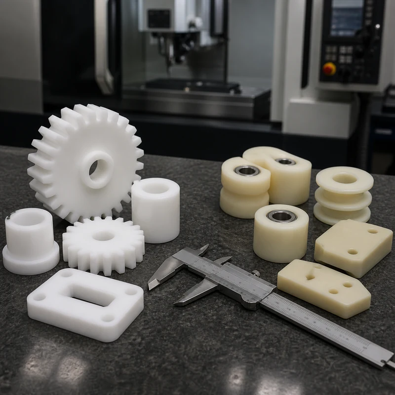
Acetal and nylon are two of the most useful engineering plastics for machined gears, rollers, bushings, guides, and structural components. They can look similar on a drawing, but they respond differently to humidity, impact, sustained load, friction, and tight tolerances. Acetal is usually the more predictable choice for dimensional stability and smooth precision motion. Nylon is often stronger when a component must absorb shock, tolerate abrasion, or flex without cracking.

This is not a simple good-versus-bad comparison. Both material families contain multiple grades, fillers, and stock forms. The right decision comes from the actual load case, environment, geometry, tolerance scheme, and inspection condition. This guide compares acetal (often specified as POM or by the Delrin trade name) with common machinable nylons from a design-for-manufacturing perspective.

Acetal vs Nylon: Quick Engineering Comparison

Decision factor Acetal / POM Nylon
Typical design priority Stable dimensions and low-friction precision motion Toughness, impact absorption, and abrasion resistance
Moisture response Low absorption; comparatively stable in humidity Absorbs moisture; dimensions and properties can change
Stiffness Generally high and consistent Grade- and moisture-dependent; often more compliant
Impact behavior Good, but less forgiving at notches Generally tougher under shock and repeated loading
Wear and sliding Excellent for controlled sliding and gears Excellent for wear pads, guides, and rugged contact
Machining behavior Clean chips and good tolerance control Can produce stringy chips and move after unclamping
Creep under load Must be checked Must be checked; reinforced grades may help
Best starting point Close fits, valve parts, precision gears, spacers Wear pads, pulleys, rollers, impact-loaded components

These are broad tendencies rather than certified values. Resin type, conditioning, reinforcement, stock-production method, temperature, test direction, and supplier all matter. Always approve the exact grade using its current technical data and any required compliance documentation.

What Is Acetal?

Acetal is the engineering-plastic family known chemically as polyoxymethylene, or POM. It is available as homopolymer and copolymer formulations. Delrin is a trade name associated with a particular acetal homopolymer, so a drawing that says only “Delrin” may not be equivalent to every generic acetal grade. Procurement documents should identify the exact resin or an approved-equivalent rule.

Machined acetal is valued for stiffness, low friction, fatigue performance, clean machinability, and low moisture absorption. These traits make it a practical choice for dimensional spacers, small gears, bearing cages, valve components, electrical insulators, and mechanisms that need repeatable motion. It also tends to produce a crisp machined surface when tools are sharp and heat is controlled.

Homopolymer vs Copolymer POM

Homopolymer POM often offers somewhat higher stiffness and strength, while copolymer grades may provide improved resistance to hot water, alkaline environments, and centerline porosity in larger cross-sections. The meaningful difference depends on grade and stock size. For a sealing bore, pressure component, or thick machined section, do not substitute between them without engineering review.

What Is Nylon?

Nylon refers to a broad polyamide family rather than one uniform material. Nylon 6, nylon 6/6, cast nylon, nylon 12, and reinforced or lubricant-filled grades can behave quite differently. Common nylons combine toughness, fatigue resistance, and excellent abrasion performance, making them useful for rollers, sprockets, wear strips, pulleys, guides, and mechanical components exposed to vibration or intermittent shock.

The defining design issue is moisture absorption. Nylon equilibrates with its surroundings, and absorbed water can change its size, stiffness, and toughness. That can be beneficial for impact behavior but problematic for a close sliding fit or a tightly located hole pattern. Engineering and inspection must agree on whether dimensions apply to dry-as-machined, conditioned, or service-equilibrated material.

The Differences That Matter in Real Parts

Dimensional Stability and Moisture

Acetal is normally easier to control when humidity changes or when the part has a close fit. Nylon can swell after machining as it absorbs moisture, and the amount is affected by grade, wall thickness, time, and exposure. A tolerance that is achievable at the machine may not represent the dimension after conditioning or field service.

For nylon, identify the conditioning state on the drawing or purchase specification. Allow clearance where function permits, avoid blanket tight tolerances, and inspect at a controlled temperature and moisture condition. For either plastic, thin walls and asymmetric stock removal can release internal stress and cause movement.

Stiffness, Toughness, and Impact

Acetal is often selected when rigidity preserves gear alignment, bearing clearance, or positional accuracy. Nylon is usually more forgiving under impact and repeated deflection. Yet geometry can outweigh the generic material trend: a sharp corner, thin snap arm, press fit, or molded-in stress raiser can fail even in a nominally tough resin.

Use generous transitions, remove sharp internal corners, distribute fastener loads, and verify short-term strength separately from long-term creep. Filled grades can increase stiffness but may reduce impact strength or create direction-dependent behavior.

Friction, Wear, and Counterface

Both families can work well in sliding mechanisms. Acetal commonly provides smooth low-friction motion and predictable gear or bearing geometry. Nylon is widely used where abrasive contact and shock occur together. Actual life depends on pressure, velocity, heat generation, lubrication, debris, shaft material, surface finish, alignment, and duty cycle—not the plastic name alone.

A wear pair should be tested as a system. A very rough metal shaft can rapidly abrade a polymer, while an excessively smooth or incompatible counterface may not retain lubricant. Filled or internally lubricated grades should be evaluated when dry running or high duty is expected.

Temperature, Creep, and Chemical Exposure

Neither material behaves like a metal under sustained heat and clamp load. Strength and modulus fall as temperature rises, and creep can relax a bolted joint or distort a bearing seat over time. Nylon grades may retain useful toughness at elevated temperature, while acetal may keep dimensions more predictably in ordinary humid service. Grade-specific curves are essential near any limit.

Both resist many oils, greases, and fuels, but neither is chemically universal. Check the exact fluid, concentration, temperature, stress level, and exposure duration. Cleaning agents, thread lockers, and assembly lubricants deserve the same review as the primary process chemical.

CNC Machining Acetal and Nylon

Machining issue Acetal planning Nylon planning
Cutting edge Sharp polished carbide; maintain a real chip Sharp positive geometry; prevent rubbing and stringy recutting
Heat control Evacuate chips and avoid dwell Control heat carefully because local softening encourages movement
Workholding Broad support without crushing Support flexible walls and avoid clamp distortion
Finishing pass Allow the part to stabilize before final sizing Rough, relax, then finish when tight geometry warrants it
Threads Good detail, but avoid excessive interference Use adequate engagement; inserts or through-bolts may be safer
Inspection Control temperature and fixturing Define moisture condition as well as temperature

Successful CNC plastic machining removes heat with the chip. Rubbing, dull tools, excessive spindle speed, or repeated chip recutting can smear an edge and build residual stress. Air or a verified compatible coolant can help, but the fluid must not attack the polymer or contaminate a regulated part.

Practical Acetal Machining Guidance

  • Use stable, traceable stock and confirm homopolymer or copolymer before production.
  • Keep cutting tools sharp and avoid dwell marks at finished surfaces.
  • Support thin rings and long walls without creating ovality or clamp witness.
  • Use realistic press-fit allowances; excessive interference can split a hub over time.
  • Deburr by controlled cutting rather than melting or heavy edge rounding.

Practical Nylon Machining Guidance

  • State the material grade and conditioning state explicitly.
  • Use positive cutting geometry and evacuate continuous chips safely.
  • For tight features, consider rough machining followed by stress relaxation and finish machining.
  • Allow the part to stabilize before final measurement.
  • Protect long, flexible features from tool pressure and workholding distortion.

How to Choose by Application

Application condition Likely starting point What to verify
Precision gear or index component Acetal Tooth load, backlash, temperature, lubricant, and life
Close-fit bushing in changing humidity Acetal PV limit, shaft finish, clearance, and creep
Impact-loaded roller or pulley Nylon Shock load, moisture state, bearing retention, and wear
Wear pad or guide rail Nylon Counterface, debris, pressure, velocity, and lubrication
Valve or fluid-handling component Acetal grade selected for media Chemical compatibility, pressure, temperature, and porosity
Large structural plastic plate Cast nylon may be attractive Flatness, internal stress, conditioning, and creep
Food or medical contact part Certified grade only Applicable regulation, traceability, cleaning, and validation

Design Rules That Reduce Failure Risk

  1. Specify the family and exact grade. “Plastic,” “nylon,” or “acetal” alone leaves too much room for substitution.
  2. Define the service environment. Include humidity, immersion, temperature range, chemicals, UV exposure, and duty cycle.
  3. Tolerance only the interfaces that matter. Plastic dimensions respond to temperature, moisture, stress, and fixturing.
  4. Avoid sharp stress concentrators. Add corner radii and smooth section changes.
  5. Design fasteners for creep. Use washers, shoulders, metal inserts, or through-bolts where appropriate.
  6. Account for thermal expansion. Do not trap a long plastic component between rigid metal boundaries without clearance.
  7. Separate cosmetic and functional surfaces. Deburring, polishing, and protective handling can affect critical edges.

Cost: Compare the Finished System, Not Stock Price

Standard nylon stock may appear less expensive than a specified acetal grade, but material price is only one input. Add machining time, stabilization steps, scrap risk, inspection, assembly method, lubrication, maintenance, and expected service life. A stable acetal part may be cheaper if it avoids post-machining movement; a tougher nylon component may be cheaper if it survives shock and abrasive duty longer.

RFQ Checklist

  • Controlled 3D model and 2D drawing
  • Exact resin, grade, color, filler, and approved equivalents
  • Stock form and required material certification
  • Quantity and prototype-to-production plan
  • Critical datums, fits, tolerances, and inspection condition
  • Load, speed, temperature, humidity, chemicals, and expected life
  • Counterface material, finish, lubrication, and debris exposure
  • Threads, inserts, press fits, assembly torque, and cosmetic requirements

MTSPi can review these inputs through its CNC machining services, dedicated acetal machining and nylon machining capabilities, and quality assurance workflow.

Frequently Asked Questions

Is Delrin the same as acetal?

Delrin is a trade name for a specific POM homopolymer. Acetal is the wider POM family, which also includes copolymers. Use the exact grade on production documents.

Which material holds a tighter tolerance?

Acetal is usually the easier starting point because it absorbs less moisture. Geometry, stock stress, temperature, fixturing, and measurement method still control the achievable result.

Which is better for gears?

Acetal suits precise, low-friction gears; nylon can suit tougher or shock-loaded gears. Tooth load, heat, lubrication, backlash, and life testing should decide.

Can nylon be machined accurately?

Yes. Accurate nylon parts require suitable stock, sharp tools, controlled heat and workholding, stabilization, and a defined moisture condition.

Can both materials use threaded inserts?

Yes, but insert style, installation method, wall thickness, torque, temperature, and creep must be validated for the exact grade.

Conclusion

Choose acetal when stable dimensions, stiffness, clean machinability, and smooth low-friction motion lead the requirements. Choose nylon when toughness, abrasion resistance, and impact absorption matter more. Then verify the decision against the exact grade, conditioning state, environment, tolerance plan, counterface, and lifetime load—not a generic property chart.

Related MTSPi Resources

Categories
Blog CNC Materials Guides Quality & Tolerances

PVC vs Acrylic: CNC Machining and Material Selection Guide

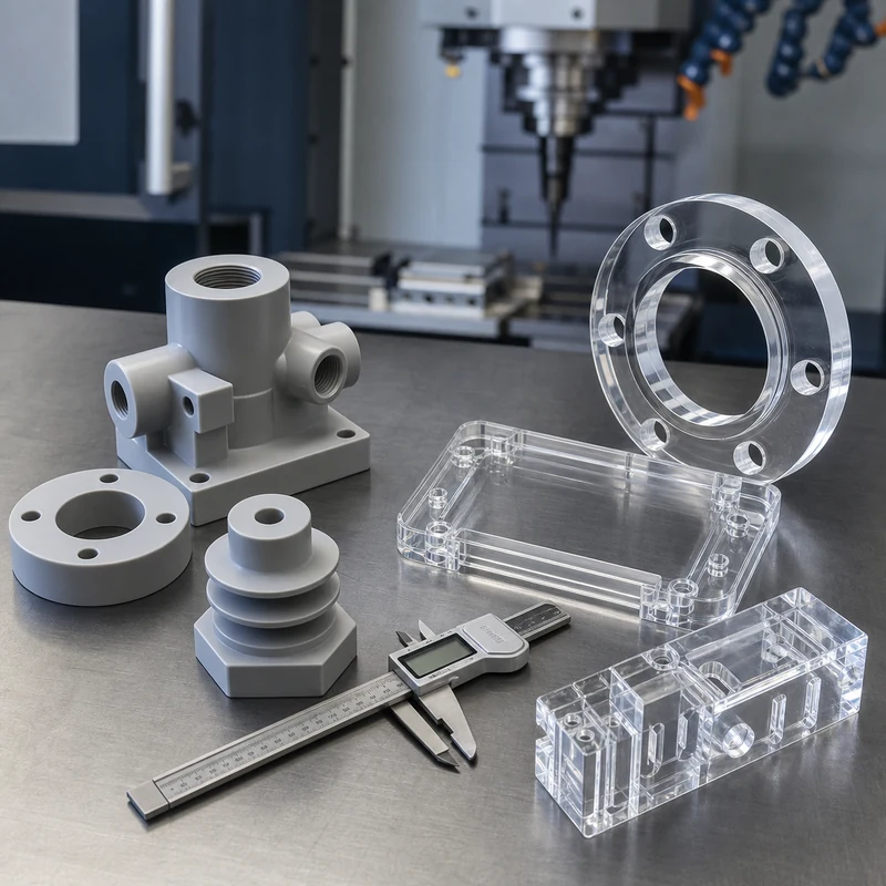
PVC and acrylic can both be machined into accurate plastic components, yet they solve different engineering problems. Rigid PVC is usually selected for chemical resistance, electrical insulation, toughness, and economical functional parts. Acrylic (PMMA) is selected when optical clarity, UV stability, a polished appearance, or visual inspection through the component matters.

The best choice cannot be made from appearance alone. Grade, service temperature, chemical exposure, impact risk, tolerances, edge finish, and fastening method all affect performance. This guide compares PVC vs acrylic from a design-for-machining perspective and explains what to include in a production RFQ.

PVC and Acrylic at a Glance

Selection factor Rigid PVC Acrylic (PMMA)
Primary advantage Chemical-resistant, economical functional performance Optical clarity and premium surface appearance
Transparency Opaque, translucent, and clear grades exist; optical quality varies Excellent clarity in optical-grade material
Impact behavior Generally tougher and less notch-sensitive Rigid but comparatively brittle
Chemical resistance Strong against many acids, alkalis, and salts Useful general resistance, but vulnerable to several solvents
Outdoor exposure Grade and stabilizer dependent Usually strong UV and weathering performance
Machining concern Heat, chip evacuation, dimensional recovery Chipping, cracking, heat, and residual stress
Typical use Manifolds, insulators, fixtures, corrosion-resistant parts Windows, guards, displays, light guides, clear housings

Property values vary by formulation, sheet or rod manufacturing method, colorant, and test standard. Designers should use the supplier’s current data for the purchased grade instead of treating a generic comparison as a material certificate.

What Is Rigid PVC?

Polyvinyl chloride is available in flexible and rigid forms. CNC components generally use rigid, unplasticized grades because they offer useful stiffness, low moisture absorption, electrical insulation, and resistance to many corrosive media. It is frequently considered for laboratory hardware, wet-process equipment, electrical components, and fluid-handling parts.

PVC is not a universal chemical solution. Temperature, concentration, exposure time, mechanical stress, and joining method can change compatibility. It also softens as temperature rises, so thin walls or clamped components require realistic thermal and creep expectations.

What Is Acrylic?

Acrylic is the common engineering name for polymethyl methacrylate (PMMA). Its defining advantage is clarity: properly selected and finished acrylic can create transparent covers, machine windows, instrument faces, lighting elements, and inspection components with a glass-like appearance at lower weight than glass.

Cast vs Extruded Acrylic

Cast acrylic is often favored for CNC machining because it typically handles cutting and polishing with lower sensitivity to localized heat and residual stress. Extruded sheet offers consistent thickness and economical availability, but its process history may make it more prone to gumming, stress, or dimensional movement. That is a practical tendency rather than an absolute rule; the actual grade and stock condition govern.

Key Engineering Differences

Optical Clarity and Finish

Acrylic is the natural choice for a view window or presentation surface. Machined edges can be brought to a clear finish through controlled sanding, polishing, or a qualified vapor/flame process. Every polishing method changes geometry and surface condition, so an appearance requirement should be separated from a critical sealing or dimensional surface.

Clear PVC exists, but it is generally specified for chemical or fabrication performance rather than maximum optical quality. A sample approval is useful whenever haze, tint, light transmission, or distortion is important.

Chemical Compatibility

Rigid PVC performs well in many aqueous chemical environments, which makes it attractive for manifolds, covers, and handling equipment. Acrylic can craze or crack after contact with incompatible solvents, cleaners, adhesives, or thread-locking compounds. Compatibility must be checked against the exact chemical, concentration, temperature, and duration. A brief wipe test does not predict long-term stressed exposure.

Impact, Notches, and Fasteners

Acrylic is stiff but notch-sensitive. Sharp internal corners, countersunk fasteners, press fits, and over-tightened screws can concentrate stress and initiate cracks. PVC usually tolerates routine handling better, although it can still deform under sustained clamp load. Add corner radii, provide clearance, distribute load with washers or inserts, and define assembly torque where necessary.

UV, Weather, and Temperature

Acrylic generally retains clarity well outdoors. PVC outdoor performance depends strongly on formulation, pigmentation, and stabilizers. Neither material is a high-temperature engineering plastic. For continuous heat, sterilization, or large thermal swings, evaluate alternatives through MTSPi’s machining materials system and account for thermal expansion in the tolerance plan.

PVC vs Acrylic for CNC Machining

Process issue PVC planning response Acrylic planning response
Tooling Sharp, polished carbide with geometry that cuts cleanly Very sharp polished tools and low-runout holders
Heat Maintain chip load and evacuate chips before they recut Avoid rubbing; control heat to prevent melting and stress
Workholding Support the part without long-term or local crushing Use broad, compliant support and avoid point loads
Edges Deburr cleanly without smearing Prevent breakout and specify whether edges remain machined or polished
Coolant/cleaner Confirm chemical compatibility Avoid stress-crazing fluids and solvents
Inspection Allow the part to reach stable temperature Protect optical faces and avoid probe or fixture damage

In CNC plastic machining, aggressive cutting is rarely the answer. The process should form a real chip instead of rubbing, while keeping heat out of the workpiece. Thin plastic parts may move after unclamping, so tolerances should reflect wall thickness, stock stress, temperature, and how the component will be supported during inspection.

Machining Rigid PVC

  • Use sharp tools and reliable extraction so stringy or warm chips do not recut.
  • Avoid excessive surface speed or dwell that can soften and smear the edge.
  • Support thin walls and large plates to limit vibration and clamping distortion.
  • Verify that coolant, adhesive, and cleaning chemistry are compatible with the selected grade.
  • Control deburring so edges are clean without being rounded beyond the drawing.

Machining Acrylic

  • Prefer stable stock and sharp, polished cutting edges.
  • Use toolpaths that reduce exit-edge breakout and sudden load changes.
  • Provide radii at internal corners rather than leaving sharp stress risers.
  • Protect cosmetic faces with appropriate film and handling controls.
  • If optical polishing is required, define the surfaces and acceptable distortion before quoting.

Design Guidance for Reliable Parts

  1. Name the exact grade and stock form. State rigid PVC or PMMA, cast or extruded acrylic where relevant, color, thickness, and any compliance needs.
  2. Prioritize tolerances. Apply tight limits only to functional interfaces; plastic movement makes blanket precision expensive and sometimes unstable.
  3. Use generous internal radii. Radii improve tool access and reduce stress concentration, especially in acrylic.
  4. Manage threads carefully. Large engagement, inserts, through-bolts, or coarse threads may be better than small deep tapped holes.
  5. Separate optical and dimensional requirements. Polishing can alter size, edge shape, and flatness.
  6. Allow for thermal expansion. A clear panel trapped in a rigid metal frame needs clearance across its full service range.

Application-Based Selection

Application Likely starting material Reason to verify
Chemical manifold or laboratory fixture Rigid PVC Exact chemical, pressure, temperature, and joining method
Electrical insulator or enclosure component Rigid PVC Voltage, flammability, heat, and certification requirements
Machine guard or inspection window Acrylic Impact standard, mounting clearance, thickness, and cleaning chemicals
Display or illuminated component Acrylic Optical grade, polish level, haze, and edge appearance
Outdoor transparent cover Acrylic UV exposure, impact, seal design, and thermal movement
Low-cost opaque spacer or bracket Rigid PVC Load, creep, temperature, and fire behavior

For a safety guard, pressure boundary, medical device, or regulated electrical assembly, generic material guidance is insufficient. The designer must verify the relevant standard and use certified material with traceability.

When Neither Material Is Ideal

Choose another engineering plastic when the application demands high impact strength, sustained high temperature, repeated steam sterilization, extreme wear, or solvent exposure that attacks both candidates. Polycarbonate may be considered for impact-critical transparent guards; PEEK, PEI, PTFE, POM, or nylon may better address other thermal, friction, or chemical requirements. The final choice should balance material behavior with machinability and inspection capability.

RFQ Checklist

  • 3D model and controlled 2D drawing
  • Exact resin grade, stock form, color, and certification
  • Quantity and prototype-to-production expectations
  • Critical dimensions, datums, flatness, and inspection method
  • Operating temperature, load, UV, moisture, and chemical exposure
  • Optical, cosmetic, edge-polish, and protective-film requirements
  • Thread inserts, adhesives, fasteners, and assembly torque
  • Required inspection report and material traceability

MTSPi can review these inputs through its CNC machining services and quality assurance workflow before production.

Frequently Asked Questions

Is PVC cheaper than acrylic?

Common rigid PVC stock is often less expensive, but finished-part cost also includes grade availability, machining time, inspection, polishing, and scrap risk.

Which is easier to CNC machine?

Rigid PVC is often more forgiving around edges, while acrylic needs closer control of heat, tool sharpness, and stress. Both can produce accurate parts with the right process.

Can acrylic hold tight tolerances?

Yes, within a realistic design. Stock stress, wall thickness, thermal expansion, clamping, polishing, and inspection temperature must be considered.

Can clear PVC replace acrylic?

Sometimes, when chemical or fabrication needs dominate. For high optical clarity, edge polish, and long-term outdoor appearance, acrylic is normally the stronger starting point.

Which is better outdoors?

Acrylic generally offers better inherent UV and clarity retention. Outdoor PVC must be selected by grade and formulation.

Conclusion

Select rigid PVC for economical functional components that need chemical resistance and electrical insulation. Select acrylic for transparent, UV-exposed, or appearance-critical parts. Then refine the decision using the exact grade, environment, geometry, fastening method, finish, and tolerance needs—not a generic material label.

Related MTSPi Resources

Categories
Blog CNC Materials Guides Quality & Tolerances

3/8-16 Tap Drill Size: CNC Threading and Design Guide

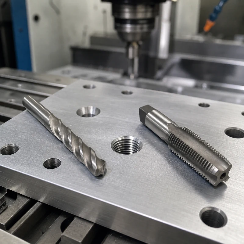
For a standard 3/8-16 UNC internal thread, the usual tap-drill recommendation is a 5/16-inch drill (0.3125 inch or 7.94 mm). That combination gives a practical balance between thread engagement, tapping torque, tool life, and assembly strength. It is a starting point, however—not a substitute for checking the material, thread class, hole depth, tap style, and joint load.

MTSPi reviews threaded features as part of its CNC machining services, including drill depth, tap clearance, edge distance, inspection access, and the risk of chip packing in blind holes.

What 3/8-16 UNC Means

The designation describes a Unified National Coarse thread. The nominal fastener diameter is 3/8 inch and there are 16 thread pitches per inch. Its pitch is 0.0625 inch (1.5875 mm). Coarse threads are commonly chosen for fixtures, machine frames, brackets, housings, and industrial assemblies because they assemble quickly and generally tolerate contamination and minor handling damage better than fine threads.

Item Nominal value Design significance
Major diameter 0.375 in (9.525 mm) Nominal screw size
Pitch 16 TPI / 0.0625 in Axial distance between threads
Common tap drill 5/16 in / 0.3125 in General-purpose cut-tap starting size
Thread family UNC Unified coarse series

Tap Drill Options and Tradeoffs

A smaller drilled hole produces greater theoretical thread engagement but also raises torque, heat, and breakage risk. A larger hole reduces cutting load but leaves less thread material. Actual results also depend on drill runout, material springback, tap geometry, coating, and whether the thread is cut or formed.

Drill Decimal diameter Typical effect
19/64 in 0.2969 in High engagement and substantially higher tapping load; use only with an engineered reason
5/16 in 0.3125 in Common general-purpose choice for a 3/8-16 cut thread
21/64 in 0.3281 in Lower engagement and lower torque; suitability must be verified against load and thread class

The simple shop approximation—nominal diameter minus pitch—also points to 0.3125 inch: 0.375 minus 0.0625. Final sizing should follow the applicable thread standard and the tap manufacturer’s data, especially for safety-critical parts.

Cut Taps, Form Taps, and Thread Milling

Method Best fit Important planning point
Cut tapping General metals and conventional threaded holes Choose spiral-point taps for many through holes and spiral-flute taps for blind-hole chip evacuation
Form tapping Ductile materials where chip-free production is useful Requires a different, larger pre-hole; never apply the cut-tap drill chart blindly
Thread milling Large, costly, difficult, or tolerance-sensitive parts Offers diameter adjustment and easier recovery if the tool fails

A Reliable CNC Process

  1. Confirm the specification. Check 3/8-16 UNC, thread class, minimum full-thread depth, through or blind condition, and any insert requirement.
  2. Spot and drill. Control drill runout and verify the actual hole rather than relying only on nominal tool size.
  3. Chamfer the entrance. A controlled lead-in helps the tap start squarely and protects the first thread.
  4. Tap or thread mill. Match speed, lubricant, and tool geometry to the work material.
  5. Deburr and clean. Remove chips without rolling burrs into the thread.
  6. Inspect. Use the specified GO/NO-GO gage and verify depth and location.

Material-Specific Notes

Material Main risk Useful control
Aluminum Built-up edge and chip adhesion Sharp geometry, suitable lubricant, and good blind-hole evacuation
Carbon/alloy steel Torque increases with hardness Rigid setup, appropriate coating, stable speed and feed
Stainless steel Work hardening and heat Avoid dwell, maintain feed, use effective lubrication
Titanium Heat concentration and seizure Conservative speed, strong lubrication, short engagement, consider thread milling

Thread Depth and Blind-Hole Allowance

The drawing should distinguish full usable thread from total drilled depth. A blind hole needs room for the drill point, tap lead, chips, and bottom clearance. Calling out an impossible full thread to the exact bottom drives unnecessary risk. As a broad design starting point, steel joints often use engagement near one nominal diameter, while lower-strength materials may need more; the joint calculation and insert strategy govern the final value.

Common Failure Modes

  • Using the form-tap pre-hole for a cut tap, or the reverse.
  • Programming feed that is not synchronized to 16 TPI during rigid tapping.
  • Ignoring tap lead length when specifying a blind thread.
  • Allowing chips to pack at the bottom of a hole.
  • Applying a tight thread requirement without defining class or gaging.
  • Placing the thread too close to an edge or thin wall.

Design and RFQ Checklist

  • State 3/8-16 UNC and the required class of fit.
  • Identify through versus blind holes and minimum full-thread depth.
  • Show counterbores, spotfaces, chamfers, inserts, and sealing functions.
  • Specify material and heat-treated condition.
  • Identify critical position tolerances and their datum references.
  • Define inspection documentation if a thread-gage record is required.

FAQ

What is the standard drill for a 3/8-16 tap?

For a conventional cut tap, 5/16 inch is the widely used starting recommendation.

Can 8 mm replace 5/16 inch?

Eight millimeters is about 0.3150 inch, slightly larger than 5/16. It may be workable in some noncritical applications, but the resulting engagement and thread requirements must be reviewed.

Is the same drill used for a form tap?

No. Form taps displace material and normally require a larger pre-hole specified by the tool maker.

How should a 3/8-16 thread be inspected?

A calibrated GO/NO-GO plug gage is common, supplemented by depth, location, and visual checks required by the drawing.

Related MTSPi Resources

Categories
Blog CNC Materials Guides Quality & Tolerances

14 Gauge Steel Thickness: Inch, mm, Weight, Uses, and Fabrication Notes

Quick answer: 14 gauge steel is commonly about 0.0747 in, or about 1.90 mm, for standard sheet steel. Exact thickness can vary by material type and gauge standard, so buyers should confirm the specification instead of relying only on the gauge number.

14 Gauge Steel Thickness Chart

Material / gauge reference Approx. thickness Notes
Standard steel, 14 gauge 0.0747 in / 1.90 mm Common reference for sheet steel
Galvanized steel, 14 gauge May differ slightly by standard Confirm coating and base metal requirements
Stainless steel, 14 gauge Often close but not always identical Check supplier chart and tolerance
Aluminum gauge Different from steel gauge Do not substitute steel gauge values for aluminum

Why Gauge Numbers Can Be Confusing

Gauge is a traditional sheet thickness system, and the same gauge number can mean different thicknesses for steel, stainless steel, aluminum, and nonferrous metals. A drawing should ideally show the actual thickness in inches or millimeters, especially when fit, weight, stiffness, or forming matters.

Common Uses for 14 Gauge Steel

  • Brackets, panels, guards, covers, and machine frames
  • Enclosures and equipment housings
  • Welded fabrication parts
  • Automotive and industrial sheet metal components
  • Fixtures, mounting plates, and support parts

Fabrication and CNC Machining Notes

14 gauge steel is thick enough for many structural sheet applications while still being practical for cutting, bending, welding, and finishing. For machined features, hole size, edge distance, bend radius, flatness, and finish requirements should be reviewed before production.

Design Checklist for 14 Gauge Parts

Design item Recommendation Reason
Hole edge distance Avoid holes too close to bends or edges Reduces tearing and distortion
Bend radius Match tooling and material condition Improves forming consistency
Tapped holes Use inserts or weld nuts when thread strength is limited Thin sheet does not provide much thread engagement
Surface finish Plan powder coating, plating, or brushing early Finishing affects appearance and protection

When to Use CNC Machined Parts Instead

If the part needs thick bosses, precise pockets, tight positional tolerances, machined sealing surfaces, or complex 3D geometry, a machined plate or billet part may be better than sheet metal. Compare options with CNC milling services and the metal material guide.

FAQ

How thick is 14 gauge steel in mm?

A common value is about 1.90 mm for standard sheet steel, but always confirm the exact standard and material.

Is 14 gauge steel strong?

It is stronger and stiffer than thinner sheet gauges, but strength depends on material grade, part shape, bends, supports, and load direction.

Can 14 gauge steel be bent?

Yes, but bend radius, tooling, grain direction, and material grade should be considered.

Is 14 gauge stainless the same thickness as 14 gauge steel?

Not always. Gauge charts can vary by material, so specify actual thickness when accuracy matters.

Need help choosing a machining route?

Send MTSPi your drawing, material, quantity, finish, and inspection requirements. We will review the part for manufacturability before quoting.

Contact MTSPi for a CNC machining quote

Practical Buyer Notes

Gauge pages can attract traffic because users often need a quick thickness answer, but they rank better when they go beyond a number. The page should explain why gauge varies by material, how thickness affects fabrication, and when CNC machining is a better option.

14 gauge steel is often used in panels, brackets, guards, housings, and fabricated assemblies. Buyers should confirm actual thickness in inches or millimeters because gauge standards are not universal across steel, stainless steel, galvanized steel, and aluminum.

How to Evaluate This Topic on a Real Drawing

Decision point Recommended approach Why it matters
Thickness callout Use exact inch or mm thickness on drawings Avoids confusion from gauge charts
Fabrication route Use sheet metal cutting and bending for thin formed parts Often cheaper than machining from billet
Machined features Use CNC when precise pockets, bores, or thick bosses are needed Sheet metal alone may not create complex 3D features
Finish Plan powder coating, plating, or brushing before quoting Finish affects edge quality and corrosion protection

Common Mistakes to Avoid

  • Assuming 14 gauge means the same thickness for every material.
  • Trying to tap strong threads directly into thin sheet without inserts or hardware.
  • Ignoring bend radius, hole-to-edge distance, and coating thickness.
  • Using gauge values instead of actual thickness on production drawings.

Recommended MTSPi Review Workflow

For gauge-related pages, MTSPi should answer the thickness first, then explain fabrication decisions, design constraints, material options, and whether CNC machining or sheet metal production fits better.

  1. Confirm the part function, operating environment, and assembly risk.
  2. Review material, process, tolerance, surface finish, and inspection requirements together.
  3. Separate critical features from general dimensions so cost is not wasted on non-functional details.
  4. Use related resources such as CNC materials, surface treatment, and quality assurance to complete the specification.
  5. Send the final drawing package to MTSPi for quote review before production.

What to Send for a Faster Quote

Send actual thickness, material grade, flat pattern or 3D model, bend notes, finish requirements, and any hardware or threaded feature expectations.

  • 3D CAD file and 2D drawing with revision number.
  • Material grade or acceptable alternatives.
  • Quantity, delivery target, and whether samples are required first.
  • Critical dimensions, thread callouts, finish notes, and inspection requirements.
  • Application notes when the part is used in heat, moisture, wear, vibration, or visible assemblies.

Conclusion

14 gauge steel is a useful thickness for durable sheet metal parts, but gauge alone is not enough for a precise manufacturing requirement. Use actual inch or millimeter thickness, define material grade, and review forming, finishing, and inspection needs before production.

Categories
Blog CNC Materials Guides Quality & Tolerances

Tungsten Metal for CNC Machined Parts: Properties, Uses, and Design Notes

Tungsten is one of the most demanding metals a CNC machining team can be asked to produce. It is dense, heat resistant, wear resistant, and useful in severe-duty applications, but those same strengths make it harder to cut, fixture, inspect, and finish than common aluminum or stainless steel parts. For engineered components, the practical question is not only what tungsten can withstand. The project also has to account for brittleness, tool wear, tolerance risk, material cost, and the right choice between pure tungsten, heavy alloy, and tungsten carbide.

MTSPi supports CNC metal machining for difficult materials and can help review tungsten part drawings before production so machining strategy, tolerances, finish, and inspection requirements are aligned early.

What Is Tungsten?

Tungsten, also called wolfram, is a metallic element with the symbol W and atomic number 74. It is best known for having the highest melting point of any pure metal. In machined-part design, it is usually selected for one of four reasons: high-temperature stability, compact mass, wear resistance, or shielding performance.

Property Typical Tungsten Value Why It Matters in CNC Parts
Chemical symbol W Useful shorthand for material specifications and alloy discussions
Density About 19.3 g/cm3 Creates high mass in compact parts such as counterweights and shielding
Melting point About 3422 C Supports high-temperature service where many metals soften
Appearance Silver-gray metallic Can be machined and finished for technical components
Hardness Very high Improves wear resistance but raises tool-wear and edge-chipping risk
Corrosion behavior Strong in many environments Still requires review against the actual chemicals and temperature

Why Engineers Choose Tungsten

Extreme Heat Resistance

Tungsten keeps useful mechanical stability at temperatures that would be unacceptable for many engineering metals. This makes it relevant for furnace hardware, high-temperature tooling, electrical contacts, aerospace systems, and other parts exposed to heat cycling.

High Density in a Small Volume

Because tungsten is much denser than steel, it can add mass without forcing a large part envelope. That is valuable for counterweights, balance components, vibration control parts, medical shielding, and compact industrial assemblies where space is limited.

Wear Resistance

Tungsten and tungsten-based materials can resist abrasion and mechanical wear. This makes them attractive for high-load components, contact surfaces, tooling-related parts, and assemblies that need a long service life under friction.

Pure Tungsten, Tungsten Alloy, and Tungsten Carbide

The word tungsten can refer to several different material families. The correct choice depends on the application and on how much machining risk the design can tolerate.

Material Main Strength Common CNC Design Note
Pure tungsten Highest temperature capability and density Brittle and difficult to machine; avoid unnecessary sharp internal features
Tungsten heavy alloy Better toughness and more practical machinability Often a better option for precision machined weights, shielding, and structural parts
Tungsten carbide Exceptional hardness and wear resistance Usually treated as a tooling or wear material rather than a normal machined metal

Advantages and Limitations

Tungsten is a high-performance choice, not a default material. It should be specified when the operating requirement justifies the manufacturing difficulty.

Advantage Manufacturing Limitation
Handles extreme temperatures Machining time is usually longer than common metals
Very high density Material cost and shipping weight can be significant
Excellent wear resistance Cutting tools wear quickly without a controlled process
Good dimensional stability in demanding service Brittleness can cause cracking, edge breakage, or scrap
Useful for shielding and compact mass Tight tolerances require stable fixturing and careful inspection planning

Applications for Tungsten Machined Parts

Industry Typical Uses Important RFQ Detail
Aerospace Balance weights, hot-zone parts, ballast, and high-density components Define load, temperature, and inspection requirements
Medical and imaging Radiation shielding, collimators, dense inserts, and instrument components Confirm material traceability and cleanliness expectations
Electronics Contacts, heat-related parts, and dense precision features Specify surface condition and burr limits
Industrial equipment Wear parts, tooling supports, vibration damping parts, and heavy-duty mechanisms Identify wear surfaces and critical fits
Research and energy High-temperature fixtures, shielding, and specialty test hardware Share operating environment and thermal cycling assumptions

CNC Machining Challenges

Tungsten machining is difficult because the material combines high hardness, high density, and limited ductility. These properties can increase cutting forces, accelerate tool wear, and make small features vulnerable to chipping. The production plan should be built around rigidity, conservative parameters, sharp tooling, coolant control, and realistic tolerance targets.

Challenge Practical Control Method
Tool wear Use suitable carbide or wear-resistant tooling and monitor tool life closely
Brittle edge damage Add sensible edge breaks, avoid fragile geometry, and control entry and exit cuts
High cutting forces Use rigid workholding, short tool overhang, and stable cutting paths
Heat at the cutting zone Tune speeds, feeds, coolant, and pass depth to protect the tool and part
Tolerance drift Inspect critical features during setup and confirm dimensions after finishing
Surface finish variation Define required roughness and whether polishing, grinding, or another finish is needed

Design Tips for Tungsten CNC Parts

  • Use tungsten only where density, heat resistance, shielding, or wear resistance is truly needed.
  • Prefer tungsten heavy alloy when the part needs better toughness and more predictable machinability.
  • Avoid extremely thin walls, knife edges, deep narrow slots, and sharp internal corners unless they are essential.
  • Call out critical dimensions clearly instead of applying tight tolerances across every feature.
  • Specify any required deburring, edge break, surface roughness, cleaning, or surface treatment.
  • Share service temperature, load, corrosion exposure, and inspection requirements with the supplier before quoting.

How MTSPi Approaches Difficult-Material RFQs

For tungsten and other difficult metals, MTSPi reviews the 3D model, 2D drawing, material callout, tolerance stack, surface finish, and expected quantity before committing to a process route. Depending on the geometry, the project may use CNC milling, CNC turning, grinding support, or multi-axis strategies such as 5-axis CNC machining. Inspection planning is handled through MTSPi’s quality assurance workflow so critical dimensions and documentation needs are clear.

FAQ

Is tungsten harder than steel?

Yes. Tungsten is harder and much denser than most common steels, which helps with wear resistance but also makes machining more difficult.

Can tungsten be CNC machined?

Yes. Tungsten can be CNC machined, but it requires appropriate tooling, rigid fixturing, controlled cutting parameters, and careful inspection.

Why is tungsten difficult to machine?

Its hardness, density, and brittleness can increase cutting force, tool wear, cracking risk, and tolerance-control difficulty.

What is the difference between tungsten and tungsten carbide?

Tungsten is a pure metal. Tungsten carbide is a tungsten-carbon compound known for extreme hardness and is often used in cutting tools and wear components.

Is tungsten more expensive than stainless steel?

Usually yes. Tungsten material and processing costs are typically higher, so the specification should be tied to a real performance need.

Related MTSPi Resources

Categories
Blog CNC Materials Guides Quality & Tolerances

18/10 vs 304 vs 316 Stainless Steel for CNC Machined Parts

18/10, 304, and 316 stainless steel are often grouped together because all three are austenitic stainless options with useful corrosion resistance. For CNC machined parts, the practical question is not just which grade sounds better. The right choice depends on corrosion exposure, machining difficulty, material cost, surface finish, passivation needs, and inspection requirements. MTSPi supports stainless steel CNC machining for prototypes and production components where grade selection affects both performance and total cost.

Quick Answer: 18/10 vs 304 vs 316

18/10 stainless steel usually describes about 18 percent chromium and 10 percent nickel. It is close to the 304 stainless family and is common in food-contact and consumer applications. 304 is the common general-purpose stainless grade for industrial parts. 316 adds molybdenum, which improves resistance to chlorides, salt exposure, and pitting corrosion, but it normally costs more and requires more careful machining control.

Material Best Use Main CNC Note
18/10 stainless steel Decorative, food-related, and consumer stainless parts Confirm the actual certified grade if the drawing requires traceability
304 stainless steel General industrial brackets, shafts, housings, fittings, and food equipment Usually easier and more economical to machine than 316
316 stainless steel Marine, chemical, medical-style, pharmaceutical, and coastal components Better corrosion resistance, with higher cost and tool-wear risk

What 18/10 Stainless Steel Means

18/10 is a composition description. Chromium helps form the passive oxide film that protects stainless steel, while nickel stabilizes the austenitic structure and improves toughness and surface appearance. The term is useful for consumer goods, but it is not always precise enough for engineered CNC parts. If a component needs material certificates, regulated traceability, or a controlled standard, the drawing should call out the recognized stainless grade rather than only saying 18/10.

Why 304 Stainless Steel Is Common in CNC Parts

304 stainless steel is widely available and offers a strong balance of corrosion resistance, availability, formability, weldability, and cost. It is often the starting point for CNC metal machining when the part needs stainless performance but will not face heavy salt, chloride, or chemical exposure. It can still work harden and create stringy chips, so sharp tooling, coolant, and stable cutting parameters matter.

Where 316 Stainless Steel Performs Better

316 stainless steel is selected when corrosion risk is the leading concern. Its molybdenum content improves resistance to pitting and crevice corrosion in chloride-rich environments. That makes 316 a better candidate for marine hardware, washdown equipment, chemical processing components, medical-style instruments, outdoor assemblies, and parts that must tolerate aggressive cleaning. It is not automatically stronger or better for every part; its main advantage is corrosion resistance.

Factor 18/10 304 316
Typical role Commercial composition description General-purpose stainless grade Harsh-environment stainless grade
Chromium About 18 percent About 18 to 20 percent About 16 to 18 percent
Nickel About 10 percent About 8 to 10.5 percent About 10 to 14 percent
Molybdenum Usually none Usually none About 2 to 3 percent
Corrosion resistance Good in mild service Good for general service Best in chloride exposure
Machinability Similar to 304-family grades Usually better than 316 More demanding
Cost Often close to 304 Usually lower Usually higher

Corrosion Resistance and Service Environment

The largest difference appears around chlorides. 304 can perform well indoors, in clean freshwater exposure, and in many general industrial assemblies. If the part sees salt water, coastal air, aggressive washdown, chemical cleaning, or trapped moisture, 316 is often safer. Geometry still matters: crevices, blind pockets, poor drainage, and scratches can reduce corrosion performance even when the alloy is well chosen.

Environment Likely Starting Grade Reason
Dry indoor machinery 304 Severe corrosion resistance is usually unnecessary
Food-contact parts 304 or 316 Cleaning chemistry decides the better option
Coastal outdoor hardware 316 Chloride exposure increases pitting risk
Marine components 316 Salt exposure favors molybdenum-bearing stainless
Decorative consumer parts 18/10 or 304-family stainless Appearance and polish may matter more than extreme corrosion resistance

CNC Machining Differences

Both 304 and 316 can be machined accurately, but neither should be treated like free-machining steel. Austenitic stainless generates heat, can work harden, and may form burrs around holes, threads, slots, and thin edges. 316 is generally more difficult because it is tougher and can increase tool wear. For tight-tolerance parts, the RFQ should define critical dimensions, surface roughness, edge requirements, and whether inspection is needed before or after finishing.

Surface Finish and Passivation

Stainless performance depends on the finished surface, not only the alloy. Machining marks, embedded contamination, sharp burrs, and poor cleaning can reduce corrosion resistance. Depending on the application, stainless parts may need passivation, electropolishing, brushing, polishing, bead blasting, or another surface treatment. Post-finish dimensions should be specified when polishing or electropolishing could affect a critical tolerance.

How to Choose for a CNC Machined Part

Choose When It Makes Sense Check First
18/10 The part is cosmetic, consumer-facing, or food-related and certification is not critical Whether a recognized 304-family grade will actually be supplied
304 The part needs general corrosion resistance, good availability, and reasonable cost Exposure to chlorides, cleaning chemicals, and outdoor weather
316 The part faces salt, chemicals, medical-style cleaning, or corrosion-sensitive service Higher material cost, machining time, and finish requirements

RFQ Details That Prevent Material Mistakes

A complete RFQ helps the supplier quote the real requirement. Include the 3D model, 2D drawing, grade and standard, material certificate requirement, production quantity, finish, inspection level, and packaging needs. MTSPi’s CNC machining materials resources can help compare stainless steel with aluminum, brass, copper, titanium, and engineering plastics before the grade is locked.

Quality Checks for Stainless Parts

Material choice should connect directly to inspection. MTSPi can support dimensional checks, thread gauges, surface roughness review, visual inspection, and documentation through its quality assurance process. For corrosion-critical parts, finish certificates or passivation records may be just as important as dimensional results.

FAQ

Is 18/10 stainless steel the same as 304?

It is usually close to 304 in composition, but 18/10 is a composition description. Use a recognized grade callout when certification or traceability matters.

Is 316 always better than 304?

No. 316 is better for chloride, marine, chemical, and harsh cleaning exposure. For mild indoor or general industrial use, 304 may be more economical.

Which grade is easier to machine?

304 is generally easier to machine than 316. Both require sharp tools, coolant control, and appropriate cutting parameters to reduce work hardening and burrs.

Can MTSPi machine 304 and 316 stainless steel?

Yes. MTSPi can quote CNC milling, CNC turning, and multi-axis machining for stainless parts based on drawings, CAD files, quantity, finish, and inspection requirements.

Related MTSPi Resources

Categories
Blog Guides Quality & Tolerances

Engineering Drawing Symbols for CNC Machining Quotes

An engineering drawing is more than a picture of a part. For CNC machining, it defines dimensions, tolerances, materials, finishes, threads, inspection requirements, and notes that control how the part should be quoted and produced.

When symbols or abbreviations are missed, the result can be an inaccurate quote, the wrong toolpath, unnecessary rework, or a part that passes size checks but fails assembly. MTSPi reviews CNC machining drawings together with CAD files so unclear requirements are caught before production.

Why Drawing Symbols Matter

A small callout can change the whole manufacturing plan. A simple hole may need drilling only, while a counterbored and tapped hole may need several tools. A general tolerance may be easy to hold, while a tight position tolerance may require a more controlled setup and CMM inspection.

Drawing information What it affects Why it matters in quoting
Dimension Feature size and tool selection Defines the basic material removal plan.
Tolerance Process choice and inspection time Tight limits can add setup and measurement cost.
Surface finish Tooling, feed, finishing, or polishing Finish requirements can change cycle time.
Hole note Drilling, boring, tapping, counterboring Compound hole features need more operations.
GD&T Datum setup and measurement method Controls relationship between features, not just size.

Common Dimension and Feature Abbreviations

Abbreviation or symbol Meaning CNC machining note
DIA Diameter Used for holes, shafts, bosses, and circular features.
R Radius Affects cutter size, corner cleanup, and stress concentration.
TOL Tolerance Defines acceptable variation from nominal size.
REF Reference Information only unless the drawing states otherwise.
THK Thickness Important for plate, sheet, wall, and step features.
DP or DEPTH Depth Controls blind holes, pockets, slots, and threaded features.

Hole and Thread Callouts

Hole notes deserve careful review because they often combine several instructions in one short line. Diameter, depth, thread size, thread depth, countersink angle, counterbore diameter, and through-hole condition can all appear together.

Callout Meaning Manufacturing impact
THRU The hole passes through the part Tool must break through the full thickness.
TAP Internal thread required Needs tapping, thread milling, or forming depending on material.
CBORE Counterbore recess Adds a flat-bottom recess for a fastener head.
CSK Countersink Adds an angled recess and angle control.
M6 x 1 Metric thread size and pitch Requires matching thread tool and inspection gauge.

Fastener features also affect assembly and cost. If a part has many tapped holes, deep threads, or difficult counterbores, review them early with reduce CNC machining cost and the intended assembly method.

Surface Finish and Inspection Notes

Surface finish symbols and roughness values control how smooth a surface must be. A cosmetic face, sealing face, sliding surface, and hidden clearance pocket should not automatically receive the same finish requirement.

Requirement What to clarify Inspection method
Ra value Which surfaces need the value Roughness tester or agreed visual standard
No burrs Edges affected and acceptable break size Visual check, magnification, or edge standard
Critical dimension Sampling plan and report format Caliper, micrometer, pin gauge, CMM, or fixture
Flatness or parallelism Datum and measurement area CMM, surface plate, height gauge, or fixture

For parts with tight tolerances, ask how the supplier will measure the feature before machining starts. MTSPi connects the drawing to CNC machining quality inspection so the inspection plan matches the acceptance requirement.

GD&T Symbols in CNC Projects

Geometric Dimensioning and Tolerancing controls the shape, orientation, and location of features relative to datums. It is especially important when parts must assemble with other components or when hole patterns, flat surfaces, and mating features need controlled relationships.

GD&T concept Plain-English meaning CNC planning issue
Datum Reference feature used for measurement Fixture and inspection setup must match the drawing intent.
Position Allowed location error of a feature Hole patterns may need controlled setup and CMM reporting.
Flatness How much a surface may vary from flat Thin parts may need stress and clamping control.
Parallelism How closely one feature aligns with another Setup sequence and datum handling matter.
Runout Circular variation during rotation Turning process and chucking method are important.

File Package Checklist for an RFQ

  • 3D CAD file for geometry, preferably STEP or another neutral format.
  • PDF drawing with tolerances, material, finish, threads, and notes.
  • Quantity, target lead time, and whether prototypes or production batches are needed.
  • Critical features that affect assembly, sealing, motion, or appearance.
  • Inspection report, material certificate, or finish documentation requirements.

Clear drawing data helps the supplier choose between CNC milling service, CNC turning service, finishing, and inspection options without guessing.

Conclusion

Engineering drawing symbols and abbreviations turn design intent into manufacturing instructions. For CNC machining, the most important items are dimensions, tolerances, hole notes, surface finish, GD&T, material, and inspection requirements. A careful drawing review before quoting saves time, reduces ambiguity, and gives both buyer and supplier a clearer path to acceptable parts.

Categories
Blog CNC Materials Guides Quality & Tolerances

420 vs 316 Stainless Steel for CNC Machined Parts

420 and 316 stainless steel are both useful CNC materials, but they solve different engineering problems. One is normally chosen for hardness and wear resistance. The other is chosen when corrosion resistance, toughness, and long service life in wet or chemical environments matter more.

For a machined part, the right choice depends on load, exposure, surface finish, heat treatment, tolerance, and inspection requirements. MTSPi reviews these tradeoffs together with stainless steel CNC machining and the full part drawing before recommending a material route.

Quick Comparison

Requirement 420 stainless steel 316 stainless steel CNC buyer note
Stainless family Martensitic Austenitic Different structures create different machining and performance behavior.
Main advantage Hardness and wear resistance Corrosion resistance and toughness Start with the part’s failure risk, not just the alloy name.
Heat treatment Can be hardened Usually not hardened by heat treatment Specify target hardness if 420 is selected for wear.
Corrosion behavior Moderate Strong, especially around chlorides 316 is usually better for marine, medical, food, and chemical exposure.
Typical CNC use Shafts, tools, wear pads, molds, blades Housings, fittings, medical parts, marine parts Geometry and environment decide the final choice.

What 420 Stainless Steel Does Well

420 stainless steel contains enough carbon to be hardened by heat treatment. After hardening, it can provide higher surface hardness and better wear resistance than many common austenitic stainless grades. That makes it useful for parts that rub, slide, cut, or need to hold a working edge.

Common examples include shafts, valve parts, mold components, wear blocks, tooling features, and mechanical parts where corrosion exposure is limited. When the part includes milled pockets, turned diameters, slots, or threaded features, MTSPi may compare CNC milling service and CNC turning service routes to control distortion and finish.

Where 316 Stainless Steel Is Stronger

316 stainless steel is usually selected when the part must survive moisture, cleaning chemicals, salt exposure, or biological and food-contact environments. Its molybdenum content improves resistance to chloride attack, which is why buyers often consider it for marine, medical, chemical, and food-processing components.

316 is not the best choice when maximum hardness is the primary requirement, but it is often a better long-term material for parts exposed to corrosive service. It also pairs well with finishing and cleaning requirements planned through surface treatment.

Machinability and Production Planning

Manufacturing factor 420 stainless steel 316 stainless steel
Tool wear Depends heavily on hardness condition Can work harden if cutting is not controlled
Heat control Important after hardening or near tight features Important because heat and rubbing can worsen work hardening
Burr risk Varies with heat treatment and feature size Can be noticeable on small holes, slots, and thin edges
Inspection focus Hardness, wear surfaces, critical diameters Corrosion-critical surfaces, finish, dimensions, passivation notes

A material that looks cheaper on paper can become expensive if it needs extra passes, slower cutting, special inspection, or post-machining treatment. The RFQ should include material condition, quantity, finish, hardness if needed, and which dimensions are critical.

How to Choose Between 420 and 316

Choose this priority Better starting point Reason
High hardness after heat treatment 420 stainless steel It can be hardened for wear and edge retention.
Marine or chloride exposure 316 stainless steel It offers stronger corrosion resistance.
Medical or cleaning-heavy environment 316 stainless steel It is commonly used where corrosion resistance and cleanliness matter.
Wear part in a mostly dry environment 420 stainless steel Hardness may matter more than corrosion resistance.
General corrosion-resistant CNC component 316 stainless steel It is often the safer choice when exposure is uncertain.

Drawing and Quality Notes

If 420 is chosen for hardness, state the target hardness range and whether heat treatment occurs before or after machining. If 316 is chosen for corrosion resistance, state any passivation, polishing, cleaning, or surface roughness requirements. These details should appear in CNC machining drawings so quoting, machining, and inspection use the same assumptions.

For higher-risk parts, combine material certificates, dimensional reports, hardness checks, and surface finish checks through CNC machining quality inspection. This reduces the chance that a material choice looks correct but fails at receiving inspection or in service.

Conclusion

Choose 420 stainless steel when hardness, wear resistance, and heat-treatable strength are the main design goals. Choose 316 stainless steel when corrosion resistance, toughness, and long-term stability in wet or chemical environments are more important. For CNC machined parts, the best decision comes from matching material behavior to the real operating environment, not from treating all stainless steels as interchangeable.

Categories
Blog CNC Machining Basics Guides Manufacturing Process Comparisons Quality & Tolerances

DMLS Dense Metal Parts: Porosity, HIP, CNC Post-Processing, and Inspection

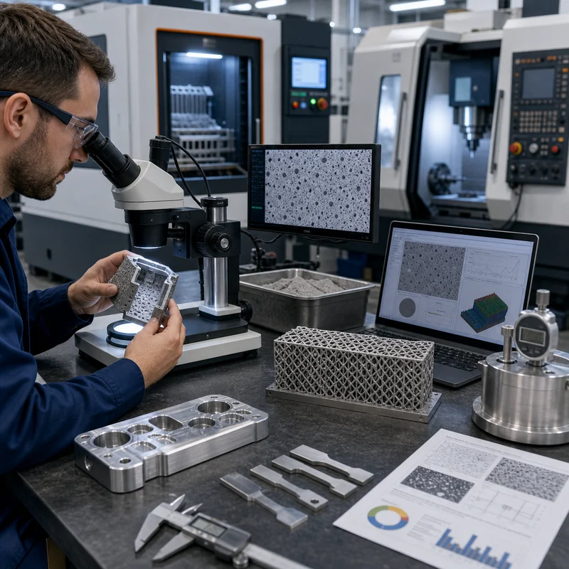
DMLS can build metal parts with impressive density, but dense does not mean simple. Metal powder quality, laser parameters, scan strategy, part orientation, support design, heat treatment, and inspection all affect the final result. For engineers, the real question is not only whether a part can be printed, but whether it can meet strength, fatigue, sealing, machining, and assembly requirements after printing.

This guide explains how Direct Metal Laser Sintering builds dense metal parts, what creates porosity, how post-processing improves performance, and when CNC machining should be used after printing. It complements MTSPi’s broader DMLS and CNC post-processing guide, but focuses specifically on density, voids, quality control, and functional metal part performance.

What Does Dense Mean in DMLS?

In DMLS, density describes how much of the part volume is solid metal compared with voids, pores, or incomplete fusion areas. A highly dense printed part has very little internal porosity. This matters because pores can reduce strength, fatigue life, pressure tightness, thermal conductivity, and confidence in critical applications.

Bulk density is sometimes reported as a percentage of theoretical density. However, a single number does not tell the whole story. The size, shape, location, and distribution of pores can matter as much as total pore volume. A few pores near a stressed surface or sealing feature may be more important than small isolated pores in a low-stress region.

How DMLS Builds Dense Metal Parts

DMLS uses a laser to fuse thin layers of metal powder. Each layer must melt or sinter consistently enough to bond with the previous layer and neighboring scan tracks. If laser energy is too low, powder may not fully fuse. If energy is too high, vaporization, spatter, or keyhole porosity can occur. Stable density depends on a balanced process window.

Process Factor How It Affects Density Engineering Note
Powder quality Particle size, shape, flowability, oxygen level, and contamination affect fusion Use qualified powder and controlled reuse practices
Laser power and speed Controls melt pool size and bonding between tracks Wrong energy can cause lack of fusion or keyhole pores
Layer thickness Affects resolution, build time, and fusion consistency Thinner layers may improve detail but increase time
Scan strategy Controls heat distribution and overlap Poor strategy can increase distortion or porosity
Shielding gas Limits oxidation and stabilizes the build atmosphere Gas flow and cleanliness matter
Part orientation Changes support needs, thermal behavior, and defect risk Orient parts with post-machining and inspection in mind

Common Types of Porosity

Not all pores have the same cause. Understanding the defect type helps engineers decide whether the issue is a process problem, design problem, material issue, or inspection requirement.

  • Lack-of-fusion porosity happens when powder or scan tracks do not bond completely.
  • Gas porosity can come from trapped gas inside powder particles or the melt pool.
  • Keyhole porosity can occur when excessive energy creates an unstable deep melt pool.
  • Contamination-related pores may appear when powder handling or atmosphere control is poor.
  • Surface-connected porosity may affect sealing, coating, fatigue, or machining results.

DMLS Density vs CNC Machined Metal

CNC machining starts from wrought, cast, forged, or extruded stock. Material density and internal quality depend on that stock form and material certification. DMLS builds the material at the same time it builds the shape, so density depends strongly on the build process. This is why DMLS parts usually need more process qualification than conventional custom CNC machining parts.

Comparison Point DMLS Metal Part CNC Machined Metal Part
Material formation Built layer by layer from powder Cut from existing billet, bar, plate, or casting
Internal defects Porosity and lack of fusion must be controlled Depends on stock quality, inclusions, casting voids, or forging quality
Geometry freedom Excellent for internal channels and lattices Limited by tool access and cutting geometry
Precision surfaces Often require post-machining Can be produced directly with suitable machining strategy
Certification focus Build parameters, powder, heat treatment, density, inspection Material certs, machining inspection, finish, heat treatment if required

Why Dense DMLS Parts Still Need Post-Processing

A dense printed part can still have rough surfaces, residual stress, support marks, dimensional variation, and features that are not accurate enough for assembly. Post-processing turns a good printed blank into a functional part. The exact sequence depends on material and application.

  • Stress relief reduces residual stress from rapid heating and cooling.
  • HIP can close some internal pores and improve fatigue performance for certain applications.
  • Support removal clears anchors and rough attachment areas.
  • CNC machining finishes datums, holes, threads, sealing faces, bearing seats, and flat surfaces.
  • Polishing, blasting, or coating controls surface finish and appearance.
  • Inspection confirms density, dimensions, and functional features.

HIP: Hot Isostatic Pressing and Density Improvement

Hot Isostatic Pressing, or HIP, uses high temperature and high pressure to reduce internal porosity in certain metal parts. It can improve fatigue life, ductility, and reliability when used correctly. HIP is common in aerospace, medical, and high-performance metal additive applications, but it is not a shortcut for poor printing practice.

Design teams should confirm whether HIP is required by the application, material, standard, or customer specification. After HIP, critical features may still need CNC machining because dimensional changes and surface requirements must be controlled.

CNC Machining After DMLS

CNC post-processing is often the practical bridge between additive geometry and precision assembly. DMLS may create an internal cooling channel, lightweight lattice, or complex bracket form, while 5-axis machining or precision milling finishes the surfaces that need to mate with other parts.

  • Machine datums first so later inspection has stable references.
  • Leave machining allowance on printed bosses, pads, holes, and sealing faces.
  • Avoid printing final precision holes unless the tolerance is loose.
  • Tap or thread-machine critical threads after printing.
  • Plan fixturing early because organic DMLS shapes can be hard to hold.
  • Use inspection data to confirm both printed and machined zones.

Design Tips for Dense DMLS Parts

A dense DMLS part starts with good design. If the part traps powder, overheats in thick sections, has unsupported overhangs, or leaves no allowance for machining, density alone will not make it successful.

  • Avoid unnecessary thick masses that create thermal gradients and long build times.
  • Use lattice structures only where they serve load, weight, airflow, or heat-transfer goals.
  • Add powder escape paths for internal cavities.
  • Design supports so they can be removed without damaging functional areas.
  • Separate as-printed surfaces from post-machined precision surfaces on the drawing.
  • Define density, porosity, and inspection requirements only where they matter.
  • Confirm whether the part needs heat treatment, HIP, or surface finishing.

Inspection Methods for Dense Metal Printed Parts

DMLS inspection can include dimensional checks, visual review, microscopy, density measurement, CT scanning, metallography, tensile coupons, hardness testing, and surface roughness measurement. For many projects, inspection should be matched to risk. A concept prototype may only need basic measurement. A pressure part, medical part, or aerospace bracket may need a much stronger quality assurance plan.

Inspection Method What It Checks When It Helps
Dimensional inspection Size, flatness, position, machined features Almost every functional part
CT scanning Internal pores, cracks, trapped powder, channels Complex or critical internal geometry
Metallography Microstructure, fusion quality, pores Process validation and high-risk parts
Tensile coupons Strength, elongation, material response Material qualification and critical builds
Surface roughness testing As-printed or machined surface condition Sealing, fatigue, flow, and cosmetic surfaces

Applications Where Density Matters

Density matters most when a part carries load, sees fatigue, holds pressure, transfers heat, or must pass strict validation. Examples include aerospace brackets, medical implants or instruments, heat exchangers, manifolds, tooling inserts with conformal cooling, lightweight robotic structures, and high-performance prototypes.

For less critical visual prototypes, density may be less important than appearance, geometry, and lead time. In those cases, polymer printing, CNC machining, or rapid prototyping with another process may be more practical.

When to Choose CNC Instead of DMLS

If a part is a simple bracket, plate, shaft, housing, or block with accessible features, CNC machining is usually the stronger first option. It typically offers better surface finish, tighter tolerances, broader material availability, and lower cost for conventional geometry. DMLS becomes more attractive when geometry complexity is doing real work.

For conventional metal parts, compare aluminum CNC machining, stainless steel CNC machining, titanium CNC machining, and other material options before committing to metal additive manufacturing.

How MTSPi Can Support Dense DMLS Projects

MTSPi focuses on CNC machining, rapid prototyping, materials guidance, surface finishing, and inspection support. If a project uses DMLS for complex geometry, MTSPi can help review the post-machined features: datums, holes, threads, sealing areas, pads, tolerances, finish requirements, and inspection needs.

Send your CAD model, drawing, material requirements, expected load case, quantity, post-machining notes, and inspection requirements through the contact page. We can help decide which surfaces should be printed, which should be machined, and where design allowances are needed.

FAQ

Can DMLS parts be as dense as wrought metal?

DMLS parts can reach high density, but equivalence to wrought metal depends on material, process qualification, heat treatment, HIP, orientation, and inspection. Critical applications should not rely on generic claims alone.

What is the biggest risk with DMLS density?

The biggest risk is hidden porosity or lack of fusion in a functional area, especially near loaded surfaces, pressure boundaries, sealing faces, or fatigue-critical regions.

Does HIP remove all porosity?

HIP can reduce or close certain internal pores, but it does not replace proper process control, design review, support strategy, and inspection.

Should DMLS holes be printed or machined?

Loose clearance holes may be printed, but precision holes, threaded holes, reamed holes, and sealing bores are usually better machined after printing.

Is DMLS good for production parts?

DMLS can be used for production when geometry, quantity, material, certification, and inspection requirements justify it. For simple shapes, CNC machining is often more practical.

Can MTSPi machine DMLS printed blanks?

MTSPi can support CNC post-processing planning for printed blanks, including machined datums, holes, threads, sealing surfaces, finishing, and inspection requirements.


Request A Quote

We'll Send You Back with Price Immediately!

DEC 1-31

XMAS SPECEIL

Up to

40% off

DMLS Dense Metal Parts: Porosity, HIP, CNC Post-Processing, and Inspection

We'll Send You Back with Price Immediately!