Categories
CNC Materials

Master Plastic Part Tolerances: A CNC Machining Guide

Getting the tolerances right for machined plastic parts is crucial for a perfect fit and function. This guide explains why they matter, how to choose them, and shares practical tips to avoid common pitfalls in your CNC projects.

Understanding Tolerances for Machined Plastic Components

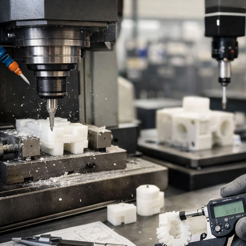
When we talk about tolerances in plastic machining, we’re simply referring to the acceptable amount of variation in a part’s dimensions. Think of it like a recipe—a little more or less of an ingredient might be okay, but stray too far and the cake won’t turn out right. In CNC machining, these dimensional limits ensure parts fit together perfectly and work as intended.

Why Getting Tolerances Right is So Important

You might wonder why we fuss over tiny fractions of a millimeter. Well, precise plastic part dimensional accuracy is the backbone of a functional assembly. Imagine a gear that’s just a hair too big—it simply won’t mesh. Or a housing that’s slightly warped, causing seals to fail. Getting the machining precision for plastics correct from the start saves time, cost, and frustration down the line by preventing fit issues and product failures.

Key Factors Affecting Plastic Part Tolerances

Several things influence how tightly we can hold those numbers on a drawing. It’s not just about the machine’s capability; the material itself plays a starring role.

Material Choice is a Big Deal

Not all plastics behave the same way under a cutting tool. For instance, stable engineering plastics like PEEK (Polyetheretherketone) or Acetal (POM) are fantastic for holding tight tolerances on plastic parts because they’re rigid and resist warping. On the other hand, softer or more flexible materials like polyethylene can be trickier, as they might deflect during machining. Always check the material’s datasheet for shrinkage rates and thermal properties—it’s your first clue to its machining behavior. Resources like Boedeker Plastics offer great material property comparisons.

Machine and Tooling Considerations

A modern, well-maintained CNC mill is your best friend here. But even the best machine needs sharp, appropriate tooling. Using a worn-out end mill on plastic can generate excess heat, leading to melting and poor surface finish, which throws off dimensions. Furthermore, the CNC machining tolerance standards you can achieve are also affected by part geometry—thin walls are more prone to vibration and deflection than solid blocks.

A Practical Guide to Setting Tolerances

So, how do you decide what numbers to put on your drawing? A good rule of thumb is to only specify a tolerance as tight as the part’s function absolutely requires. Tighter tolerances almost always mean higher cost.

Standard vs. Tight Tolerances: When to Use What

For most non-critical features, a standard machining tolerance of ±0.1 mm (±0.004″) is a great starting point and is generally economical. Reserve tighter specs, like ±0.025 mm (±0.001″), for critical mating surfaces, press-fit holes, or optical components. Asking for “±0.005 mm everywhere” is a common request we see, but it’s often overkill and drives up the price unnecessarily. For detailed guidelines on geometric dimensioning, the ASME standards are the industry reference.

Tips for Communicating with Your Machinist

The clearest way to communicate your needs is with a well-dimensioned drawing that calls out critical tolerances explicitly. Don’t just write “tight tolerance” in a note—specify the number! Also, share the part’s purpose. Telling us, “This surface mates with an O-ring seal,” immediately tells us where to focus our precision efforts. This collaboration is key to optimizing the manufacturing tolerances for engineered plastics.

Common Mistakes and How to Avoid Them

Let’s look at a few frequent hiccups. One major issue is not accounting for thermal expansion in plastic components. A part machined to perfection in a warm shop might measure differently in a cold environment. Another is overlooking post-machining stress relief; some plastics can slowly warp after material is removed. The fix? We recommend you design with these factors in mind, choose stable materials, and allow parts to normalize to their operating temperature before final inspection. By understanding these nuances of plastic fabrication tolerances, you’re well on your way to mastering the art of precision plastic parts.
Categories
CNC Materials

Mastering High Precision Aluminum Parts: A CNC Machining Guide

Creating high-precision aluminum components requires a blend of the right tools, techniques, and knowledge. This guide walks you through the essential steps, from material selection to finishing, to help you achieve exceptional accuracy and surface quality in your CNC machining projects.

Achieving Micron-Level Accuracy in Aluminum Machining

When we talk about machining high precision aluminum parts, we’re often dealing with tolerances tighter than a human hair. It’s a fascinating process that goes beyond just running a program. Think of it like a chef preparing a delicate dish—the quality of the ingredients, the sharpness of the knives, and the control of the heat all matter immensely. The goal here is consistent, repeatable accuracy for your precision aluminum components.

The Foundation: Material Choice

Not all aluminum is created equal for high-tolerance machining. Alloys like 6061-T6 are incredibly popular for a reason: they offer an excellent balance of machinability, strength, and cost. For even more demanding applications, you might look at 7075, which is stronger but can be a bit trickier to machine. The key is to match the alloy to the part’s function. Starting with a predictable, high-quality material is half the battle won for your CNC aluminum part fabrication.

The Role of Machine Rigidity

Your CNC mill or lathe is the stage for this performance. For true precision aluminum part production, a rigid machine is non-negotiable. Any flex or vibration translates directly into chatter marks and dimensional errors on your workpiece. It’s the difference between using a sturdy workbench and a wobbly card table. A well-maintained machine with minimal backlash is your best friend here.

Essential Tools and Techniques for Precision

Once your material and machine are set, the real artistry begins with tooling and technique. This is where you fine-tune the process to achieve those mirror-like finishes and hold those tight tolerances for aluminum CNC machining services.

Selecting the Right Cutting Tools

Using the wrong tool is like trying to slice a tomato with a butter knife. For aluminum, we almost always use sharp, polished carbide end mills. You might find that tools with three flutes often provide a great balance between chip evacuation and finish. For intricate details, smaller diameter tools are a must, but they require careful handling to avoid breakage. Don’t forget about tool runout—even a tiny misalignment can ruin your chances at tight tolerance aluminum machining.

Mastering Feeds and Speeds

This is the heart of the process. Running too slow can cause rubbing and poor finish, while too fast can lead to tool wear or failure. Aluminum loves high spindle speeds. A good starting point is to use a CNC machining calculator, but always be prepared to adjust based on sound and chip formation. Beautiful, consistent “C” shaped chips usually mean you’re in the sweet spot. It’s a skill that comes with practice, much like finding the right rhythm when you’re driving.

Workholding and Coolant Strategies

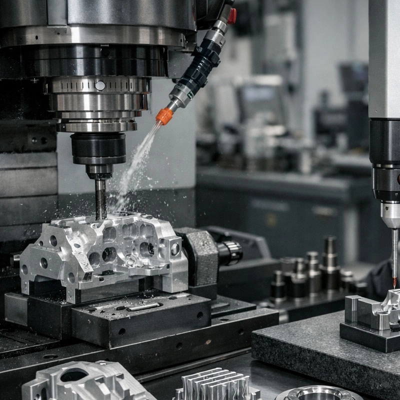
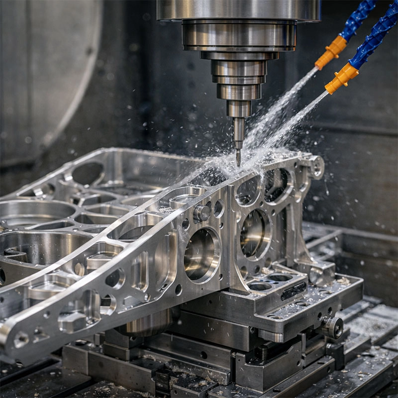
A part that moves or gets too hot is a part that ends up out of spec. Proper workholding is absolutely critical for manufacturing precision aluminum parts. We prefer using a vacuum chuck or custom machined soft jaws for complex shapes, as they provide even, distortion-free clamping over the entire surface. For coolant, a flood system is standard, but for ultra-fine detail work, a mist system can be more effective at keeping the cut zone cool without overwhelming it. The goal is to manage heat and hold the part rock-solid.

Post-Machining: The Finishing Touches

The journey doesn’t end when the CNC program finishes. Deburring is a meticulous hand process to remove sharp edges. For parts requiring exceptional smoothness or specific aesthetic qualities, processes like vibratory finishing or anodizing are common. Anodizing, for instance, not only adds color and corrosion resistance but can also be a final check—it will often highlight any subtle surface imperfections you might have missed. You can learn more about this versatile process from resources like the Aluminum Anodizers Council.

Common Pitfalls to Avoid

Let’s talk about a few common hiccups so you can steer clear. First, neglecting to let the material and machine acclimate to the shop temperature can cause thermal expansion issues. Second, trying to take too deep of a cut in one pass to save time often leads to tool deflection and poor accuracy. Finally, skipping regular tool wear inspection is a surefire way to have a batch of parts slowly drift out of tolerance. Remember, consistency is king in high-precision component machining. For deeper dives into metallurgy and standards, referencing authoritative sources like the ASM International handbook can be incredibly valuable.

Categories
CNC Materials

Mastering CNC Machining for Aerospace Materials: A Practical Guide

Working with aerospace alloys like titanium and Inconel presents unique challenges. This guide explores practical CNC strategies for these demanding materials, focusing on toolpath optimization, thermal management, and achieving the stringent tolerances required for flight-critical parts.

Advanced Techniques for Machining Aerospace Components

When you’re tasked with CNC milling aerospace materials, it’s not just about running a program. It’s a dance between machine, tool, and material. I like to think of it as a conversation where you need to listen to the cut. The goal is to remove material efficiently while preserving the integrity of the part, which is often incredibly expensive. You might find that strategies which work for steel fall completely flat here.

Smart Toolpath Strategies

One of the biggest shifts is moving towards trochoidal milling and other high-efficiency toolpaths. Instead of forcing a tool through a full width of cut, these paths use a constant, lighter engagement, allowing the tool to “glide” through the material. This reduces heat buildup and radial forces dramatically. For complex aerospace component machining, this means longer tool life and a much happier machine spindle. It’s a bit like taking smaller, quicker steps up a steep hill instead of trying to leap up in one go—you conserve energy and avoid burnout.

Keeping Your Cool: Thermal Management

Heat is the enemy. Many high-performance alloys used in aviation are designed to retain strength at high temperatures, which is great for the engine, but tough on your end mill. Effective cooling is non-negotiable. We recommend using high-pressure coolant through the spindle (HPCTS) to flood the cutting edge and evacuate chips instantly. Sometimes, for materials like certain aluminums, even a mist coolant can be sufficient if chip clearance is optimal. The key is to prevent the heat from transferring back into the tool or the workpiece, which can cause work hardening and premature tool failure.

Navigating the Challenges of Aerospace Alloys

Let’s get specific about the rock stars of the aerospace world: titanium and nickel-based superalloys. Each has its own personality, and understanding them is half the battle in precision machining for aviation.

Tackling Titanium’s Toughness

Machining titanium alloys like Ti-6Al-4V is a study in contradiction. It’s strong but has low thermal conductivity, meaning the heat stays right at the cutting edge. The chatter you might hear? That’s often a sign of built-up edge or excessive vibration. To win, you need sharp, coated carbide tools, conservative speeds and feeds, and absolute rigidity in your setup. A colleague once shared that machining titanium taught him more about machine stability than any other material—it simply won’t tolerate a loose setup.

Conquering Inconel’s Heat

If titanium is tough, Inconel machining is on another level. These superalloys work-harden rapidly. If your tool dwells or rubs, you instantly create a surface harder than the tool itself. The strategy here is aggressive—maintain a constant, positive cut. Use ceramic or specialized carbide inserts designed for high-temperature applications. It’s crucial to calculate your feeds to ensure the cut is always ahead of the work-hardened zone. Think of it like walking on hot coals; you have to keep moving steadily forward.

Achieving Aviation-Grade Precision and Tolerances

What separates a good part from a flight-ready part? The answer lies in microns and surface finishes. Aerospace CNC machining isn’t just about shape; it’s about creating components that can handle immense stress and thermal cycles without failing. This demands extraordinary attention to detail in every operation, from roughing to final finishing.

For instance, achieving a specific surface finish on a turbine blade isn’t just for looks; it directly impacts airflow and fatigue life. This often involves a multi-stage process with dedicated finishing tools and precise control over stepovers. Furthermore, managing material stress and distortion is part of the job. Sometimes, this means using stress-relief cycles between machining operations or even designing fixtures that mimic the part’s final mounted state. You can learn more about material properties and standards from resources like ASM International.

Your Practical Checklist for Success

Let’s wrap this up with some hands-on advice you can take straight to the shop floor. Mastering CNC manufacturing for aerospace is a journey, but these tips will set you on the right path.

Start with the Right Tools: Don’t compromise. Use premium, sharp tools with coatings like AlTiN for titanium or specialized grades for superalloys. They cost more but save money in the long run.
Embrace Rigidity: Check everything—tool holder runout, workpiece clamping, machine condition. Vibration is your biggest foe.
Manage Chips: A well-evacuated chip is a cool chip. Ensure your coolant pressure and nozzle positioning are optimized to get chips out of the cut zone immediately.
Document Everything: Speeds, feeds, tool life, surface finish results. When you find a recipe that works for a specific aerospace-grade material, write it down. This knowledge is pure gold.
Partner with Experts: Engage with your tooling supplier and material providers. They have a wealth of application-specific data. Repositories like NASA’s Technical Reports Server can also provide fascinating insights into advanced manufacturing research.

Remember, patience and a methodical approach are your best assets. By respecting the material, leveraging advanced techniques, and focusing on relentless precision, you’ll not only machine aerospace components—you’ll master them.

Categories
CNC Materials

Stainless Steel 304 vs 316: Which is Easier to Machine?

Choosing between 304 and 316 stainless steel for your CNC machining project? It often comes down to machinability. While both are popular austenitic grades, their chemical makeup leads to different behaviors on the shop floor. Let’s break down the key differences to help you pick the right material for easier, more efficient machining.

Machinability Comparison: 304 vs 316 Stainless Steel

So, you’re setting up for a job and need to decide between machining 304 stainless steel or its cousin, 316. From my experience on the floor, this is a common crossroads. Both are fantastic materials, but when it comes to pure ease of machining, one has a clear edge. Let’s talk about why.

The Molybdenum Factor

The core difference lies in chemistry. Type 316 contains 2-3% molybdenum, while 304 has none. This addition is fantastic for corrosion resistance, especially against chlorides (think saltwater or certain chemicals). However, molybdenum also increases the alloy’s strength and toughness at high temperatures. In practical terms, this means the 316 alloy is harder and more ductile during the CNC milling or turning process. The tool meets more resistance, leading to faster wear, higher cutting forces, and generally a more challenging cut compared to working with grade 304.

Work Hardening Tendency

Both grades are notorious for work hardening, which is a key consideration in stainless steel fabrication. If your tool dwells or feeds too slowly, the material hardens at the point of cut, making subsequent passes even tougher. While both do this, 316’s inherent toughness can make this effect slightly more pronounced. You might find that maintaining consistent, aggressive cuts and sharp tools is even more critical when processing 316 stainless to avoid getting stuck in a hardened zone.

Practical Machining Tips for Both Grades

Alright, let’s get practical. Whether you’re working with the more forgiving 304 or the tougher 316, a few universal rules apply. First, use sharp, premium carbide tools. Blunt tools are the enemy here, as they increase heat and work hardening. Second, maintain rigid setups and use positive rake angles to shear the material cleanly. For coolant, a good flood is your friend—it keeps heat down and helps clear chips. A pro tip I’ve picked up: when machining type 316 stainless, consider reducing your surface speed (SFM) by about 20% compared to your 304 parameters. It gives the tool a fighting chance against that extra toughness.

Common Misconceptions and Clarifications

I often hear folks say, “316 is just a better version of 304, so it must be better for everything.” That’s not quite right. For CNC machining services, “better” depends on the application. If your part needs supreme corrosion resistance in a harsh environment, 316 is the champion, even if it’s harder to machine. But for most general applications—brackets, housings, consumer goods parts—304 offers excellent corrosion resistance and is significantly easier on your tools and cycle times. Don’t over-specify the material; choosing 304 for an indoor part can save you time and money without sacrificing performance. You can learn more about their general properties from authoritative sources like the AZoM materials database.

Making the Right Choice for Your Project

So, which is easier to machine? For the vast majority of us in the shop, stainless steel grade 304 wins in terms of machinability. It allows for higher speeds, causes less tool wear, and is generally more predictable. Reserve type 316 machining for projects where its specific corrosion-fighting superpowers are non-negotiable. Always start with a clear understanding of the part’s end-use environment. By matching the material to the actual requirement, you ensure a smoother machining process, happier tools, and a successful project. When in doubt, consult your material supplier or a trusted machining guide—they’re invaluable resources for making the final call.

Categories
CNC Materials

Master Thin Wall Aluminum Machining: 5 Expert Tips for Success

Machining thin-walled aluminum parts is a common yet challenging task in CNC workshops. This guide breaks down the process into five actionable expert tips, focusing on practical strategies to prevent chatter, distortion, and tool failure, helping you achieve precise, high-quality results every time.

Understanding the Challenge

So, you’ve got a job for machining thin wall aluminum components. It might be a lightweight aerospace bracket or a complex electronic enclosure. I get it—these parts look simple on the drawing but can be a real headache on the shop floor. The core issue is rigidity, or rather, the lack of it. When you’re dealing with thin-wall aluminum machining, the material is prone to flexing, vibrating (that awful chatter sound!), and distorting from cutting forces and heat. It’s like trying to slice a ripe tomato with a dull knife; you end up crushing it instead of getting a clean cut. Successfully machining thin walled aluminum parts isn’t about brute force; it’s a finesse game. Let’s walk through five key areas where a little expert knowledge makes all the difference.

Tip 1: Master Tool Selection and Geometry

Your first line of defense is choosing the right cutter. This isn’t the time for that old, slightly worn end mill. For aluminum thin wall machining, you need tools designed to cut smoothly and efficiently.

Sharp, High-Helix End Mills

Opt for end mills with a high helix angle (around 45° or more) and sharp, polished flutes. A high helix creates a shearing action that lifts chips up and out of the cut cleanly, reducing the force pushing against the thin wall. Tools specifically designed for aluminum milling, often with three flutes, offer an excellent balance of material removal and finish. Remember, a sharper tool requires less cutting pressure, which is exactly what our delicate part needs.

The Climb Milling Strategy

Always use climb milling (also called down milling). In this direction, the cutter teeth engage with the maximum chip thickness at the start of the cut and taper off to zero. This pulls the workpiece into the cutter, minimizing deflection and providing a cleaner surface finish on the thin wall. Conventional milling pushes the workpiece away, which can cause the wall to vibrate and chatter.

Tip 2: Optimize Feeds and Speeds for Stability

Finding the sweet spot in your CNC parameters is crucial. The goal is to maintain a consistent, light chip load. Running too slow can cause the tool to rub and generate excessive heat, softening the aluminum and leading to built-up edge. Running too aggressively will simply bend or break the wall.

We suggest you start with a higher spindle speed and a moderate-to-high feed rate. This might sound counterintuitive, but a faster feed per tooth ensures the cutter is *cutting* more than it’s *rubbing*. It creates thinner, cooler chips that carry heat away. A great resource for dialing in these numbers is the HSMAdvisor software, which specializes in calculating optimal parameters for challenging materials and geometries. The key takeaway for thin wall part machining is to prioritize a stable, continuous cut over maximum material removal rate.

Tip 3: Rethink Workholding and Fixturing

How you hold the part is just as important as how you cut it. Standard vises clamping directly on a thin feature are a recipe for distortion. You need to support the wall directly opposite the cutting forces.

Strategic Support is Key

For internal pockets, use custom soft jaws or fixture plates that match the part’s contour, providing full backing to the thin floor or side wall during machining aluminum thin walls. For external walls, consider strategic clamping away from the cut area and using removable support tabs or “bridges” in your CAD model that are machined away in the final operation. This extra material provides crucial rigidity during the bulk of the CNC milling process.

Consider Vacuum Fixturing

For large, plate-like thin parts, vacuum chucks are a game-changer. They distribute holding force evenly across the entire back surface, virtually eliminating clamping distortion and allowing you to machine most features in a single setup. It’s one of the most effective methods for precision thin wall machining.

Tip 4: Employ Smart Toolpath Strategies

Modern CAM software is your best friend here. Ditch the traditional constant-stepover toolpaths for more intelligent options. Trochoidal or adaptive clearing paths maintain a constant tool engagement angle, preventing the cutter from getting overloaded in corners—a common failure point. For finishing the final wall, use a spring pass. This is a second, identical finishing pass that removes any material that may have sprung back after the first cut due to residual stress or deflection, ensuring true dimensional accuracy for your thin-walled aluminum components.

Tip 5: Proactively Manage Heat and Chip Evacuation

Heat is the enemy of dimensional stability. Aluminum expands when heated, and if the part gets too hot during machining thin sections, it will be out of spec when it cools. Use plenty of coolant, preferably flood coolant, to both control temperature and flush chips away. Re-cutting chips (recutting) is a major source of heat and poor surface finish. For deep pockets, consider peck milling or using an air blast to ensure chips are cleared from the cutting zone. Keeping everything cool and clean is a simple but non-negotiable rule.

Putting It All Together

Mastering thin wall aluminum fabrication is about a holistic approach. It’s the synergy of a sharp, correct tool; stable, calculated cutting parameters; intelligent workholding; smart CAM programming; and diligent thermal management. Start by analyzing your part to identify the most fragile features, then build your process around supporting and cutting them gently. Don’t be afraid to make test cuts on scrap material. With these five expert tips, you’ll transform a daunting job into a routine success, producing strong, precise, and chatter-free thin wall parts that meet the tightest tolerances. Happy machining!

Categories
CNC Materials

Aluminum 6061 vs 7075: Which is Best for Your CNC Machining Project?

Choosing the right aluminum alloy for your CNC machining project is crucial. This guide breaks down the key differences between the popular 6061 and 7075 grades, focusing on their machinability, strength, and cost to help you make the best decision for your specific application.

Comparing Machinability: Aluminum 6061 vs 7075

When you’re planning a CNC machining job, one of the first questions is often about material choice. Two of the most common options you’ll encounter are aluminum 6061 and aluminum 7075. Both are fantastic, but they behave quite differently on the machine. Think of it like choosing between a reliable sedan and a high-performance sports car—both get you there, but the experience and purpose vary. Let’s dive into their machinability characteristics to see which one might be the better fit for your shop floor.

The Workhorse: Machining 6061 Aluminum

If you’ve machined aluminum before, chances are you’ve worked with 6061. It’s often called the “workhorse alloy” for good reason. Aluminum 6061-T6 is incredibly forgiving and easy to work with. Its machinability rating is excellent, meaning you can use higher feed rates and achieve a beautiful surface finish without too much fuss. It produces relatively long, manageable chips, which makes life easier for both the operator and the machine. For general-purpose parts, brackets, enclosures, or prototypes, 6061 is usually the go-to choice. It’s the friendly, predictable material that rarely gives you surprises.

The High-Performer: Machining 7075 Aluminum

Now, let’s talk about the powerhouse: 7075 aluminum alloy. This material is in a different league when it comes to strength. However, that extra strength comes with a different machining behavior. While still considered good to machine, 7075 is harder and more abrasive than 6061. You might find you need to adjust your speeds and feeds, use sharper tools, and pay more attention to chip evacuation. It can produce shorter, more fragmented chips. The reward, though, is a part with exceptional strength-to-weight ratio. It’s perfect for aerospace components or high-stress structural parts where every gram and every bit of strength counts.

Strength, Weight, and Cost: The Practical Trade-offs

Okay, so we know how they machine, but what about the numbers? This is where the decision often gets real. Aluminum 7075-T6 is significantly stronger than 6061-T6—we’re talking about nearly double the tensile strength in some cases. It’s also harder, which contributes to better wear resistance. On the flip side, both alloys have very similar densities, so weight savings purely from material choice are minimal; the savings come from being able to design a thinner, lighter part because the material is stronger.

Then there’s cost. Here, 6061 aluminum almost always wins. It’s more readily available and less expensive both in raw material form and often in machining costs due to its easier workability. 7075 commands a premium. So, you have to ask: does my application *need* the extra strength of 7075, or will the cost-effectiveness and ease of machining aluminum 6061 serve me just as well? For many projects, 6061 offers the best balance of performance and price.

Which Aluminum Alloy Fits Your Project?

Let’s make this practical. How do you decide between aluminum 6061 vs 7075 for CNC? It boils down to your project’s requirements. I like to tell people to start by listing the top three needs for the part: is it strength, cost, machinability, corrosion resistance, or something else?

When to Choose Aluminum 6061-T6

Choose 6061-T6 if your priority is a great all-around balance. It’s ideal for:
Prototypes and Functional Models: You get parts quickly and cost-effectively to test form and fit.
Automotive and Consumer Parts: Think brackets, frames, chassis, and housings that require good strength and weldability.
Marine and General Structural Applications: It has good corrosion resistance, especially with proper surface treatment.
In short, if you’re not pushing the absolute limits of material performance, 6061 is probably your best bet. It’s the versatile champion for most CNC machining projects.

When to Choose Aluminum 7075-T6

Reach for 7075-T6 when performance is non-negotiable. It’s the specialist for:
Aerospace and Defense Components: Wing spars, fuselage fittings, and other critical parts where failure is not an option.
High-Stress Mechanical Parts: Gears, shafts, and mold tooling that undergo significant cyclic loading.
Competition Sports Equipment: Bicycle frames, rock climbing gear, and baseball bats where saving weight while maximizing strength is key.
Remember, 7075 is generally not recommended for welding, and its corrosion resistance is lower than 6061, so it often needs protective coatings.

Pro Tips for Machining Both Alloys

Whichever alloy you choose, a few best practices will ensure success. For machining 6061, use sharp, polished carbide tools to get that mirror-like finish. Coolant is your friend to prevent material buildup on the tool. For machining 7075, rigidity is even more critical. Ensure your workpiece is clamped securely and your machine is stout to handle the higher cutting forces. You might use a more robust tool geometry and pay close attention to chip control.

Always consult the material data sheets for specific parameters. A great resource for official specifications is the ASM Material Data Center. And don’t forget about post-processing! Both alloys anodize well, but 6061 typically gives a more uniform color for decorative anodizing.

So, which is best for your project? If you need maximum strength for a critical component and budget allows, 7075 aluminum is your high-performance partner. For the vast majority of other applications where weldability, cost, and excellent machinability are top priorities, 6061 aluminum remains the trusted, versatile choice. Happy machining!

Categories
CNC Materials

Discover the Best Materials for CNC Machining: A Practical Guide

Choosing the right material is a crucial first step in any CNC project. This guide walks you through the most common and effective materials, from metals like aluminum and stainless steel to plastics and composites, helping you match their properties to your specific application needs for a successful outcome.

Why Your Material Choice Matters So Much

Hey there! If you’re diving into a new CNC project, you’ve probably realized there are tons of material options out there. It can feel a bit overwhelming, right? I’m here to tell you that picking the optimal CNC machining material isn’t just a technical step—it’s the foundation of your entire project. The right choice affects everything: how long it takes to machine, the final finish, the part’s strength, its cost, and even how it behaves in the real world. Think of it like choosing ingredients for a recipe; the best dish starts with the best, most suitable components. Whether you’re making a lightweight drone arm or a heavy-duty gear, understanding CNC material properties is your first step to success.

Top Metals for CNC Machining

Let’s talk about metals first. They’re the backbone of many CNC milling materials and CNC turning materials lists, and for good reason. They offer a fantastic balance of strength, durability, and machinability. Here’s a breakdown of the most popular ones you’ll encounter.

Aluminum Alloys: The Go-To Favorite

If I had to pick one material that’s the superstar of the CNC shop, it would be aluminum. Specifically, alloys like 6061 and 7075. Why? They’re incredibly easy to machine, which means faster production times and less tool wear. They’re also lightweight and have a great strength-to-weight ratio, making them perfect for aerospace parts, automotive components, and consumer electronics. 6061 is your all-around workhorse, while 7075 offers higher strength. For more detailed specs on aluminum grades, a great resource is the ASM Handbook series.

Stainless Steel: For Strength and Shine

When you need corrosion resistance and serious strength, stainless steel is the answer. Grades like 304 and 316 are common for food-grade or marine applications. For even higher strength and wear resistance, people often look at 17-4 PH or 416. The catch? Stainless is tougher on your tools than aluminum, so machining it requires more power and careful planning. But for parts that need to last under stress and resist rust, it’s a top-tier choice for precision machining materials.

Mild Steel and Other Common Metals

Don’t overlook good old mild steel (like A36) or alloy steels (like 4140). They’re cost-effective, very strong, and weldable, ideal for structural frames, brackets, and tooling. Brass and copper are also excellent CNC machining metals when you need electrical conductivity, corrosion resistance, or that distinctive aesthetic look for custom fittings and decorative pieces.

Top Plastics and Composites for CNC

Plastics and composites open up a whole new world of possibilities. They’re essential when you need electrical insulation, chemical resistance, or a lower-cost prototype. The key is knowing which plastic fits your CNC fabrication needs.

Delrin® (Acetal): The Precision Plastic

Ask any machinist about their favorite plastic to cut, and many will say Delrin (acetal homopolymer). It machines beautifully—leaving a smooth, low-friction finish—and is dimensionally stable. It’s the go-to for making gears, bushings, and insulators. If you’re looking for easy to machine materials for CNC in the plastic family, start here.

Nylon: Tough and Versatile

Nylon is another fantastic option, known for its toughness, wear resistance, and slight flexibility. It’s great for parts that need to endure impact or friction. You might find it in wear pads, fasteners, or functional prototypes. Just remember, it can absorb moisture, which might affect dimensions in very humid environments.

PTFE (Teflon®) and PEEK

For extreme applications, we move into high-performance polymers. PTFE (like Teflon) has incredible chemical resistance and the lowest coefficient of friction, perfect for seals and linings. PEEK is a superstar engineering plastic that retains its properties at high temperatures and is biocompatible, used in medical and aerospace. These are more challenging to machine but solve unique problems. The Boedeker Plastics resource center is a helpful place to learn more about these advanced materials.

How to Choose: Matching Material to Your Project

So, with all these options, how do you decide? I like to break it down by asking a few simple questions. First, what does the part *do*? Does it need to be strong, lightweight, conductive, or chemically inert? Second, what’s your budget? Material cost and machinability of metals directly impact the final price. Third, consider the environment. Will it be outdoors, in contact with chemicals, or inside the human body? Finally, think about appearance and finish. Answering these will quickly narrow down your list of suitable materials for CNC and point you toward the best fit.

Common Mistakes to Avoid

Let’s wrap up by looking at a few pitfalls I’ve seen folks run into. One big one is choosing a material based only on its raw cost, without factoring in machining difficulty. A cheaper, harder-to-machine metal might end up costing more in labor and tooling than a slightly pricier, easier one. Another is overlooking material grain direction or thermal properties, which can cause warping or poor finishes. And finally, not prototyping with a cheaper, easier material first! It’s often wise to test your design in a basic plastic or aluminum before committing to expensive stainless or titanium. Avoiding these missteps will make your journey to finding the best stock for CNC machining much smoother.

Categories
CNC Materials

5 Common Copper CNC Machining Problems & How to Fix Them

Working with copper on a CNC machine can be tricky. While it’s a fantastic material, its unique properties often lead to specific machining challenges. This guide walks you through the most frequent issues, like tool wear and surface finish problems, and offers practical, friendly advice on how to solve them for smoother, more efficient production runs.

Excessive Tool Wear and Breakage

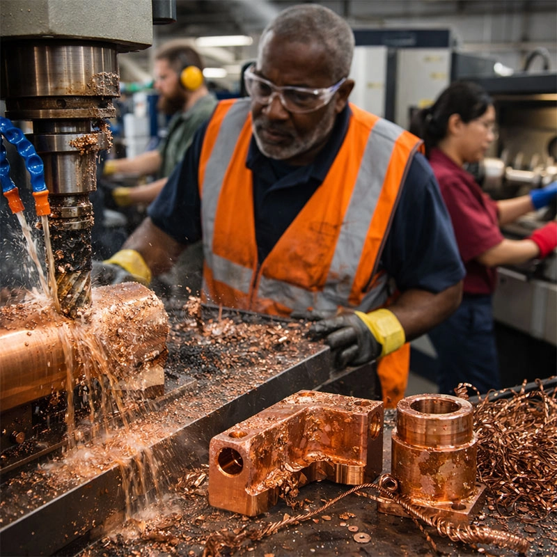
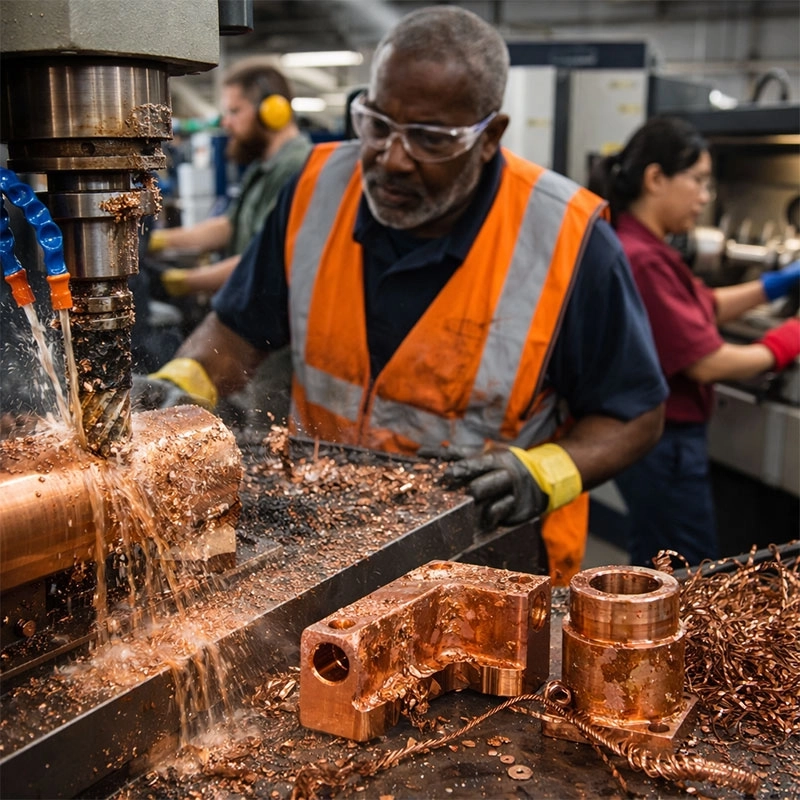
If you’ve ever felt like you’re going through end mills faster than usual when milling copper, you’re not alone. Copper’s high ductility and softness mean it doesn’t always break away cleanly. Instead, it can sort of “smear” and create a lot of friction and heat against the cutting tool’s edge. This friction is the main culprit behind rapid tool degradation in copper CNC operations. You might notice the flutes of your tool getting worn down quickly, or worse, experiencing sudden tool failure mid-cut.

Choosing the Right Tools and Parameters

The fix here is a two-part strategy: tool selection and machine settings. First, let’s talk tools. For machining pure copper or high-copper alloys, we highly recommend using sharp, polished tools. Uncoated carbide end mills with a high positive rake angle are often a great choice because they slice through the material more easily, reducing cutting forces. Some machinists swear by diamond-coated tools for long production runs, as copper doesn’t react chemically with diamond. You can read more about advanced tool materials on Modern Machine Shop.

Next, dial in your parameters. Running at too high a surface speed can generate excessive heat, accelerating wear. Conversely, too slow a feed rate lets the tool rub instead of cut. Finding that sweet spot with a higher feed per tooth and a moderate spindle speed is key. It encourages a cleaner shear and helps the tool last longer. Think of it like slicing a soft tomato with a dull knife versus a sharp one—the right tool and a confident motion make all the difference.

Poor Surface Finish and Built-Up Edge

Nothing is more frustrating than a part that looks streaky, rough, or has tiny bits of material welded to its surface. This is a classic sign of built-up edge (BUE), a major headache in copper machining. When the heat and pressure get too high, tiny particles of the workpiece material can actually weld themselves to the cutting edge of your tool. This lump then acts as a poor, irregular cutting surface, scratching and tearing the copper instead of shearing it cleanly.

Optimizing for a Clean Cut

To combat BUE and achieve a mirror-like finish on your copper parts, focus on reducing heat and ensuring a sharp cut. Using a generous flow of coolant is non-negotiable. It not only cools the tool and workpiece but also helps wash away chips before they can be re-welded. For finishing passes, increase your cutting speed slightly and take lighter depths of cut. This reduces the contact time and pressure, minimizing the chance for material to adhere. Sometimes, switching to a tool with a different geometry or a sharper cutting edge can instantly solve these surface quality issues.

Material Adhesion and Galling

Closely related to BUE is the broader problem of galling. Copper is famously “sticky.” During the cutting process, under pressure, it can cold-weld to the tool material, especially if both are similar metals. This isn’t just about the tool’s edge; it can happen on the tool’s flutes or even in the workpiece itself, leading to torn surfaces and dimensional inaccuracies. This material sticking is a pervasive issue that requires proactive prevention.

Keeping the Tool and Part Separate

Lubrication is your best friend here. A high-quality, free-cutting fluid designed for non-ferrous metals creates a barrier between the tool and the copper. If you’re dealing with especially gummy copper alloys, consider using tools with specialized coatings. Titanium Aluminum Nitride (TiAlN) or similar coatings can reduce the affinity between the tool and the workpiece. Also, ensure your toolpath strategy avoids letting the tool dwell in the cut, as constant motion helps prevent localized heating and pressure that lead to galling.

Managing Heat and Thermal Expansion

Copper is an excellent conductor of heat, which is great for heat sinks but tricky for machining. The heat generated during cutting doesn’t just stay at the tool-chip interface; it rapidly conducts into the workpiece itself. This can cause the part to expand slightly during machining. When it cools down after the job is done, it contracts, potentially throwing your carefully machined dimensions out of tolerance. This thermal distortion is a subtle but critical problem for precision components.

Cooling Strategies and Speeds

To manage heat in copper CNC milling, a robust cooling system is essential. Flood coolant is ideal as it provides constant temperature control for both the tool and the part. For internal features where flood coolant might not reach, a through-tool coolant system can be a game-changer. On the programming side, use climb milling whenever possible. This technique allows the chip to be at its thickest at the beginning of the cut and thinnest at the end, which typically carries heat away with the chip more effectively than conventional milling. Taking multiple lighter finishing passes instead of one heavy cut also gives the material time to dissipate heat between operations.

Chip Control and Evacuation Issues

Long, stringy, continuous chips are the hallmark of machining ductile materials like copper. These “birds’ nests” are more than just a nuisance; they are a genuine hazard. They can wrap around the toolholder or spindle, scratch finished surfaces, clog coolant lines, and even cause machine crashes if they build up enough. Effective chip management is crucial for safe and efficient copper part production.

Effective Chip Breaking and Removal

The goal is to make chips that are small and easy to evacuate. You can achieve this through tool geometry and cutting parameters. Using an end mill with chip-breaking geometry (often called a “chip breaker”) is highly effective. These tools have small notches or variations in the cutting edge that help curl and break the chip into manageable pieces. Adjusting your feed rate and depth of cut can also promote chip breaking—a higher feed rate often creates a thicker, more brittle chip that breaks more easily. Finally, never underestimate the power of a strong coolant flow or compressed air blast to physically push chips out of the cutting zone and into the conveyor or pan. For in-depth discussions on chip formation, resources like The Engineering Toolbox can provide valuable technical background.

Categories
CNC Materials

Master Machining Hardened Steel: 5 Pro Tips for Success

Machining hardened steel can be a real challenge, but with the right approach, it’s entirely manageable. This guide breaks down five expert strategies to help you achieve better surface finishes, extend tool life, and boost your productivity when working with this tough material.

Tip 1: Master Your Tool Selection

Think of your cutting tool as the star player on your team. When you’re machining hardened steel, you can’t just send anyone onto the field. The hardness of the workpiece, often above 45 HRC, demands a specialist. The most common question I get is, “Can I use carbide?” While premium micro-grain carbide can work for lighter cuts, for serious hard turning or hard milling operations, you need to look at the super-hard materials.

The Power of CBN and PCD

For steels hardened above about 50 HRC, Cubic Boron Nitride (CBN) inserts are often the go-to choice. They offer fantastic heat resistance and wear characteristics. For even higher hardness or when working with abrasive materials, Polycrystalline Diamond (PCD) tools might be the answer, though they are typically used for non-ferrous metals. The key is to choose a tool with a sharp, honed edge and a strong geometry to withstand the pressure. A blunt tool will just generate more heat and fail quickly. You can learn more about the properties of these advanced materials from authoritative sources like the ASM International website.

Tip 2: Dial in Your Speeds and Feeds

Getting your cutting parameters right is where the magic happens. A classic mistake is running the spindle too slow. It sounds counterintuitive, but with hardened materials, you often need a higher surface speed to create a shearing action rather than a rubbing one, which generates excessive heat. However, the feed rate needs to be conservative. We’re talking about light, consistent cuts here. A good starting point is to use a high speed with a low feed per tooth. This balance helps control cutting forces and directs heat into the chip, not your workpiece or tool. Remember, every machine and setup is different, so start with tool manufacturer recommendations and be prepared to tweak.

Tip 3: Prioritize Absolute Rigidity

This tip is non-negotiable. Machining high hardness steel amplifies any weakness in your setup. Any chatter or vibration will instantly destroy your tool’s edge and ruin the surface finish. So, how do we achieve this? First, minimize tool overhang as much as physically possible. Use the shortest, stoutest tool holder you can. Second, ensure your workpiece is clamped rock-solid. If you’re doing CNC machining of hardened components on a mill, consider using a vise with step jaws or custom fixtures. On a lathe, a collet chuck often provides better grip than a standard jaw chuck for small, hardened parts. A rigid setup is your best defense against unpredictable results.

Tip 4: Manage Heat with Coolant Strategy

Heat is the enemy when working with hardened steel. The wrong coolant approach can lead to thermal shock and micro-cracks. There are two main schools of thought, and both are valid. The first is a high-pressure, through-tool coolant system. This method effectively flushes chips away and cools the cut at the source. The second is dry machining or using an air blast. This avoids the rapid heating and cooling cycle that can damage the workpiece. If you use coolant, make sure it’s a high-quality synthetic or semi-synthetic type designed for heavy-duty operations. The goal is consistent temperature management, not wild fluctuations.

Tip 5: Optimize Your Tool Paths

Your CAM programming strategy makes a huge difference. Forget about old-school, full-depth radial cuts. For hard material machining, we want constant engagement and smooth tool movement. Techniques like trochoidal milling or peel milling are fantastic. They keep the tool moving in a circular, rolling path, which maintains a more consistent load and allows for better heat dissipation. When finishing, use a small stepover with a high speed to get that beautiful mirror-like surface. A well-planned tool path reduces stress on the tool, the machine, and the part, leading to longer tool life and superior accuracy. It’s worth spending extra time here to save headaches later.

Categories
CNC Materials

Master PEEK Machining: 5 Critical Considerations for Success

Machining PEEK plastic successfully hinges on understanding its unique properties. This guide covers the five most critical factors, from tool selection to cooling, to help you achieve precise, high-quality parts without the common headaches.

Understanding PEEK’s Unique Nature

Hey there! If you’re diving into PEEK CNC machining, the first step is to get to know the material itself. Think of PEEK (Polyether Ether Ketone) not as a typical plastic, but more like a high-performance engineering polymer with an attitude. It’s incredibly strong, chemically resistant, and can handle high temperatures that would make other plastics wilt. But these very strengths are what make machining peek plastic a bit tricky. It’s abrasive, which can wear down tools quickly, and it has a tendency to soften rather than chip cleanly if you’re not careful. Getting a handle on these quirks is your foundation for success.

Key Material Properties

Let’s break down what makes PEEK tick. Its high abrasiveness is a top consideration for machining peek. This isn’t your average Delrin; it demands respect for your cutting tools. Also, PEEK has a low thermal conductivity. This means the heat generated during cutting doesn’t dissipate easily and stays concentrated at the tool-workpiece interface. If not managed, this heat can soften the material, leading to poor surface finishes and dimensional inaccuracy. Finally, its rigidity is a double-edged sword—great for part stability, but it means any vibration or chatter will show up on your finished part. Keeping these peek polymer machining characteristics in mind guides every other decision you’ll make.

Tool Selection and Geometry

Choosing the right tool is half the battle won. For effective PEEK material machining, you’ll want tools that are harder than the material’s abrasive nature. We highly recommend solid carbide end mills. They offer the necessary hardness and rigidity. As for coatings, an uncoated or a polished tool often works best to reduce friction and prevent material from sticking. The geometry is crucial too: use sharp cutting edges with high positive rake angles. This shears the material cleanly instead of pushing it, reducing heat and stress. A larger helix angle also helps in efficient chip evacuation, which is a key part of best practices for machining peek.

Mastering Speeds, Feeds, and Depth of Cut

Finding the sweet spot in your machining parameters is critical. Running too slow can cause rubbing and heat buildup, while too fast can lead to tool deflection and poor finishes. A good starting point is a high spindle speed with a moderate to high feed rate. This promotes a good chip load, carrying heat away with the chip. For cnc machining peek tips, we suggest using a lighter depth of cut (DOC) and a higher width of cut (stepover). This keeps the tool engaged in a cooler part of the material and minimizes deflection. It’s all about balancing aggression with control to manage heat and tool pressure—two of the biggest challenges of peek machining.

Workholding and Cooling Strategies

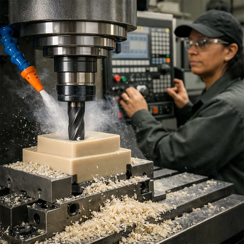
Because PEEK is sensitive to heat and clamping pressure, your setup matters a lot. Use secure, but gentle, workholding to avoid distorting the part. Vacuum chucks or custom soft jaws are excellent choices. Now, let’s talk cooling. While some machinists use compressed air, a mist coolant system is often the best friend for high performance plastic machining. It provides both cooling and lubrication without drenching the part, which is important as PEEK can absorb moisture. The goal is to keep the cutting zone cool without causing thermal shock. Proper chip evacuation, often assisted by coolant, is non-negotiable to prevent re-cutting chips and marring the surface finish.

Post-Machining and Quality Checks

Your job isn’t over when the spindle stops. PEEK parts can retain internal stresses, so allowing them to stabilize for a short time before final measurement is a smart peek fabrication consideration. Deburring requires a gentle touch; manual methods with sharp blades or fine abrasive pads are preferable to aggressive power tools. When inspecting, pay close attention to critical dimensions and surface finish. Look for signs of melting, burning, or micro-cracks, which indicate excessive heat during the processing peek on cnc operation. A final clean with isopropyl alcohol will remove any coolant or oil residue. Taking these extra steps ensures the outstanding properties of your PEEK component are fully realized.

Request A Quote

We'll Send You Back with Price Immediately!

DEC 1-31

XMAS SPECEIL

Up to

40% off

Master PEEK Machining: 5 Critical Considerations for Success

We'll Send You Back with Price Immediately!