Categories
Blog CNC Materials Quality & Tolerances

Is Bronze More Expensive Than Copper? CNC Cost Guide

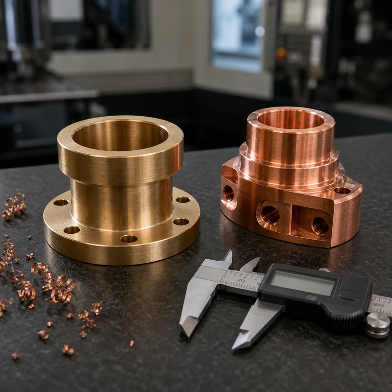
Bronze is not automatically more expensive than copper. The answer changes with alloy grade, stock form, order size, metal-market conditions, and the work required to turn the stock into an inspected part. Commercially pure copper can carry a higher material price than a common bearing bronze, while specialty aluminum-bronze or nickel-bearing grades may cost considerably more.

For a CNC project, price per kilogram is only a starting point. Yield loss, cutting time, tool wear, deburring, inspection, finishing, and service life can outweigh a small difference in raw stock. This guide explains how engineers and buyers can compare copper and bronze on a finished-part basis.

Bronze vs Copper Cost: The Short Answer

Question Copper Bronze
What is it? A base metal; grades range from high-purity copper to alloyed copper A family of copper alloys, commonly containing tin, aluminum, silicon, or nickel
Typical cost position High-purity and oxygen-free grades may command a premium Common grades may be competitive; specialty grades can be costly
Primary value Electrical and thermal conductivity Wear resistance, strength, bearing behavior, or corrosion resistance
Machining cost tendency Ductile grades can produce burrs and difficult chips Many bearing bronzes cut cleanly; tough specialty grades may be slower
Best comparison Exact grade, temper, form, certification, and finished-part quote Exact grade, condition, form, certification, and finished-part quote

There is no reliable universal percentage difference. Commodity prices move, distributors apply different minimums, and a round bar can be priced differently from plate, tube, or a near-net casting of the same nominal alloy. Request quotations using the same quantity, dimensions, certification, and delivery terms.

Why Alloy Grade Changes the Answer

Copper is an element, but industrial copper products still come in many grades. High-conductivity copper, tellurium copper, chromium-zirconium copper, and oxygen-free copper have different performance and supply economics. Bronze is an even broader label: tin bronze, phosphor bronze, aluminum bronze, silicon bronze, and nickel aluminum bronze are not interchangeable.

Alloying additions change strength, hardness, corrosion behavior, casting response, and machinability. Tin, nickel, and other additions also have their own market prices. A material called bronze may therefore be less expensive, similar in price, or more expensive than the copper grade being considered.

Common Copper Choices

  • High-conductivity copper: selected for busbars, electrodes, heat spreaders, and electrical contacts.
  • Oxygen-free copper: used where conductivity, vacuum behavior, or high purity is critical.
  • Free-machining copper alloys: useful when manufacturability must improve without abandoning copper-based performance.
  • Precipitation-hardened copper alloys: selected when greater strength or thermal fatigue resistance is required.

Common Bronze Choices

  • Phosphor bronze: combines strength, fatigue resistance, and useful spring or bearing behavior.
  • Bearing bronze: designed for sliding contact, bushings, thrust washers, and wear components.
  • Aluminum bronze: offers high strength and strong corrosion resistance for demanding mechanical parts.
  • Silicon bronze: valued for corrosion resistance and fabrication characteristics.
  • Nickel aluminum bronze: chosen for severe marine, pump, valve, and high-load applications.

Seven Factors That Drive Finished-Part Cost

1. Current Metal Value

Copper is a globally traded metal, so changes in its market price affect both copper stock and copper-rich bronze. Bronze price also reflects its alloying additions. A quote should have a validity period because a delayed purchase may be exposed to a different surcharge.

2. Stock Form and Availability

Standard bar diameters and plate thicknesses are generally easier to source than an unusual tube, large continuous-cast section, or certified specialty alloy. Minimum order quantities and mill lead time can dominate a prototype order. A designer may reduce cost by choosing a nearby standard size without compromising the final geometry.

3. Buy-to-Fly or Material Yield

A part machined from oversized solid stock can generate far more chips than finished product. Bronze bushings may be economical from hollow bar or near-net cast stock, while a copper heat sink may still require solid plate. Compare the purchased mass, recoverable scrap, and machining allowance—not just finished mass.

4. Machinability

Many pure copper grades are ductile and prone to built-up edge, long chips, smearing, and heavy burrs. Some bearing bronzes machine cleanly and hold stable features, but hard aluminum-bronze and nickel-bearing grades can demand rigid setups and suitable tooling. The exact alloy determines cycle time.

5. Geometry and Tolerances

Deep pockets, slender walls, small internal radii, interrupted cuts, and tight positional tolerances increase setup and inspection effort for either metal. Blanket tolerances can create cost without adding function. Mark the truly critical interfaces and use practical tolerances elsewhere.

6. Finishing and Quality Requirements

Polishing, plating, passivation-like cleaning specifications, conductivity testing, material traceability, first-article inspection, and dimensional reports all affect the quote. Requirements should be stated at RFQ stage so suppliers compare the same scope.

7. Quantity and Supply Risk

Setup cost matters more for one prototype than for a production batch. Conversely, a high-volume program needs stable mill supply and alloy traceability. A nominally cheaper specialty alloy can become expensive if it is available from only one source or requires a large minimum buy.

CNC Machining Copper and Bronze

Manufacturing issue Copper planning Bronze planning
Chip control Use sharp positive tools and prevent built-up edge Confirm grade; many cut cleanly, while high-strength grades need robust tooling
Burr formation Expect careful edge control on ductile grades Often more manageable, but geometry and grade still matter
Heat Conducts heat rapidly; manage distortion and tool interface Lower conductivity than pure copper; monitor localized heat
Workholding Avoid marking soft conductive surfaces Support cast or hollow stock and control clamping distortion
Inspection Define flatness, conductivity, and cosmetic surfaces Define bearing fits, surface finish, and alloy certification
Cost lever Select a machinable grade when conductivity allows Match strength and corrosion performance without overspecifying alloy

Successful CNC machining begins with an exact material callout. A drawing that says only “copper” or “bronze” invites substitutions and inconsistent quotations. Include the UNS or recognized alloy designation, temper or condition, stock form, and permitted equivalents.

When Copper Is the Better Economic Choice

Copper is usually justified when electrical or thermal performance is central to the design. Busbars, electrodes, power contacts, induction components, and heat-transfer parts can lose their purpose if replaced with a lower-conductivity alloy. Paying more for copper may eliminate extra mass, reduce resistance, or improve heat flow.

Do not automatically specify the highest-purity grade. If a moderately alloyed copper meets conductivity requirements and machines faster, it may lower the completed-part price. Review the balance through MTSPi’s copper CNC machining capability and validate any material change with functional testing.

When Bronze Can Deliver Lower Lifetime Cost

Bronze often earns its place in bushings, wear plates, gears, valve components, marine hardware, and sliding interfaces. Its strength, galling resistance, corrosion behavior, and compatibility with shafts can extend service intervals. Even if the initial part costs more, reduced downtime or replacement frequency may lower the cost per operating hour.

For a bearing application, evaluate pressure, sliding speed, lubrication, shaft finish, alignment, temperature, contamination, and required life. A premium bronze cannot compensate for poor clearance or a rough counterface.

How to Reduce Cost Without Weakening the Design

  1. Name the exact alloy. Eliminate ambiguity before suppliers quote.
  2. Choose standard stock. Adjust noncritical dimensions to available bar, tube, or plate where practical.
  3. Compare near-net options. Hollow stock or casting may reduce waste on rings and housings.
  4. Use functional tolerances. Tighten only datums, fits, sealing faces, and interfaces that need control.
  5. Design accessible features. Avoid unnecessary deep cavities, sharp internal corners, and multiple setups.
  6. Combine demand. Larger releases can distribute programming and setup cost, provided storage and cash flow make sense.
  7. Compare service life. Include wear, maintenance, energy loss, and replacement downtime.

Material Selection by Application

Application Likely starting point Verify before release
Electrical busbar or contact High-conductivity copper Conductivity, temperature rise, plating, and joint design
Heat spreader or cooling plate Copper Thermal path, weight, coolant compatibility, and flatness
Sliding bushing Bearing or phosphor bronze PV limit, lubrication, shaft hardness, and clearance
Marine pump or valve component Suitable aluminum-bronze family Fluid chemistry, galvanic pairing, strength, and certification
Spring contact Phosphor bronze or copper alloy Fatigue, conductivity, forming direction, and plating
Decorative hardware Copper or bronze by appearance Patina, coating, handling, and outdoor exposure

RFQ Checklist for a Fair Comparison

  • 3D model and controlled 2D drawing
  • Exact alloy designation, temper, and approved alternatives
  • Required stock form and material certification
  • Prototype and production quantities
  • Critical tolerances, datums, surface finish, and inspection report
  • Conductivity, hardness, pressure, wear, or corrosion requirements
  • Finishing, plating, cosmetic zones, and packaging
  • Target delivery and quote-validity expectations

MTSPi’s machining materials resources and quality assurance workflow can support alloy review, manufacturability feedback, and inspection planning before production.

Frequently Asked Questions

Is bronze always more expensive than copper?

No. A common bronze may cost less than high-purity copper, while a specialty bronze containing costly alloying elements may cost more. Compare exact grades and forms on the same date.

Which is easier to machine?

Many bearing bronzes machine more cleanly than ductile pure copper. However, high-strength bronze grades can be demanding. Machinability must be judged by alloy, temper, geometry, and tooling.

Does bronze last longer?

Bronze often lasts longer in sliding, wear, and some corrosive environments. Copper remains preferable when electrical or thermal conductivity is the dominant function.

Can scrap value offset machining cost?

Recoverable chips have value, but segregation, cleanliness, volume, and local recycler terms matter. Scrap credit rarely cancels inefficient geometry or excessive stock removal.

Should I choose by price per kilogram?

No. Use finished-part cost and lifetime performance. Include purchased stock, yield, cycle time, tools, inspection, finishing, assembly, maintenance, and expected life.

Conclusion

Bronze may be cheaper or more expensive than copper depending on the exact comparison. Copper usually wins when conductivity is indispensable; bronze often wins when strength, wear resistance, bearing behavior, or corrosion performance governs. The defensible decision is based on a specified alloy and a complete finished-part quotation, followed by verification in the real service environment.
Related MTSPi Resources

Categories
Blog CNC Materials Guides Quality & Tolerances

Acetal vs Nylon: CNC Machining and Material Selection Guide

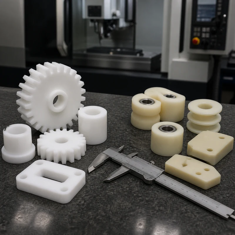
Acetal and nylon are two of the most useful engineering plastics for machined gears, rollers, bushings, guides, and structural components. They can look similar on a drawing, but they respond differently to humidity, impact, sustained load, friction, and tight tolerances. Acetal is usually the more predictable choice for dimensional stability and smooth precision motion. Nylon is often stronger when a component must absorb shock, tolerate abrasion, or flex without cracking.

This is not a simple good-versus-bad comparison. Both material families contain multiple grades, fillers, and stock forms. The right decision comes from the actual load case, environment, geometry, tolerance scheme, and inspection condition. This guide compares acetal (often specified as POM or by the Delrin trade name) with common machinable nylons from a design-for-manufacturing perspective.

Acetal vs Nylon: Quick Engineering Comparison

Decision factor Acetal / POM Nylon
Typical design priority Stable dimensions and low-friction precision motion Toughness, impact absorption, and abrasion resistance
Moisture response Low absorption; comparatively stable in humidity Absorbs moisture; dimensions and properties can change
Stiffness Generally high and consistent Grade- and moisture-dependent; often more compliant
Impact behavior Good, but less forgiving at notches Generally tougher under shock and repeated loading
Wear and sliding Excellent for controlled sliding and gears Excellent for wear pads, guides, and rugged contact
Machining behavior Clean chips and good tolerance control Can produce stringy chips and move after unclamping
Creep under load Must be checked Must be checked; reinforced grades may help
Best starting point Close fits, valve parts, precision gears, spacers Wear pads, pulleys, rollers, impact-loaded components

These are broad tendencies rather than certified values. Resin type, conditioning, reinforcement, stock-production method, temperature, test direction, and supplier all matter. Always approve the exact grade using its current technical data and any required compliance documentation.

What Is Acetal?

Acetal is the engineering-plastic family known chemically as polyoxymethylene, or POM. It is available as homopolymer and copolymer formulations. Delrin is a trade name associated with a particular acetal homopolymer, so a drawing that says only “Delrin” may not be equivalent to every generic acetal grade. Procurement documents should identify the exact resin or an approved-equivalent rule.

Machined acetal is valued for stiffness, low friction, fatigue performance, clean machinability, and low moisture absorption. These traits make it a practical choice for dimensional spacers, small gears, bearing cages, valve components, electrical insulators, and mechanisms that need repeatable motion. It also tends to produce a crisp machined surface when tools are sharp and heat is controlled.

Homopolymer vs Copolymer POM

Homopolymer POM often offers somewhat higher stiffness and strength, while copolymer grades may provide improved resistance to hot water, alkaline environments, and centerline porosity in larger cross-sections. The meaningful difference depends on grade and stock size. For a sealing bore, pressure component, or thick machined section, do not substitute between them without engineering review.

What Is Nylon?

Nylon refers to a broad polyamide family rather than one uniform material. Nylon 6, nylon 6/6, cast nylon, nylon 12, and reinforced or lubricant-filled grades can behave quite differently. Common nylons combine toughness, fatigue resistance, and excellent abrasion performance, making them useful for rollers, sprockets, wear strips, pulleys, guides, and mechanical components exposed to vibration or intermittent shock.

The defining design issue is moisture absorption. Nylon equilibrates with its surroundings, and absorbed water can change its size, stiffness, and toughness. That can be beneficial for impact behavior but problematic for a close sliding fit or a tightly located hole pattern. Engineering and inspection must agree on whether dimensions apply to dry-as-machined, conditioned, or service-equilibrated material.

The Differences That Matter in Real Parts

Dimensional Stability and Moisture

Acetal is normally easier to control when humidity changes or when the part has a close fit. Nylon can swell after machining as it absorbs moisture, and the amount is affected by grade, wall thickness, time, and exposure. A tolerance that is achievable at the machine may not represent the dimension after conditioning or field service.

For nylon, identify the conditioning state on the drawing or purchase specification. Allow clearance where function permits, avoid blanket tight tolerances, and inspect at a controlled temperature and moisture condition. For either plastic, thin walls and asymmetric stock removal can release internal stress and cause movement.

Stiffness, Toughness, and Impact

Acetal is often selected when rigidity preserves gear alignment, bearing clearance, or positional accuracy. Nylon is usually more forgiving under impact and repeated deflection. Yet geometry can outweigh the generic material trend: a sharp corner, thin snap arm, press fit, or molded-in stress raiser can fail even in a nominally tough resin.

Use generous transitions, remove sharp internal corners, distribute fastener loads, and verify short-term strength separately from long-term creep. Filled grades can increase stiffness but may reduce impact strength or create direction-dependent behavior.

Friction, Wear, and Counterface

Both families can work well in sliding mechanisms. Acetal commonly provides smooth low-friction motion and predictable gear or bearing geometry. Nylon is widely used where abrasive contact and shock occur together. Actual life depends on pressure, velocity, heat generation, lubrication, debris, shaft material, surface finish, alignment, and duty cycle—not the plastic name alone.

A wear pair should be tested as a system. A very rough metal shaft can rapidly abrade a polymer, while an excessively smooth or incompatible counterface may not retain lubricant. Filled or internally lubricated grades should be evaluated when dry running or high duty is expected.

Temperature, Creep, and Chemical Exposure

Neither material behaves like a metal under sustained heat and clamp load. Strength and modulus fall as temperature rises, and creep can relax a bolted joint or distort a bearing seat over time. Nylon grades may retain useful toughness at elevated temperature, while acetal may keep dimensions more predictably in ordinary humid service. Grade-specific curves are essential near any limit.

Both resist many oils, greases, and fuels, but neither is chemically universal. Check the exact fluid, concentration, temperature, stress level, and exposure duration. Cleaning agents, thread lockers, and assembly lubricants deserve the same review as the primary process chemical.

CNC Machining Acetal and Nylon

Machining issue Acetal planning Nylon planning
Cutting edge Sharp polished carbide; maintain a real chip Sharp positive geometry; prevent rubbing and stringy recutting
Heat control Evacuate chips and avoid dwell Control heat carefully because local softening encourages movement
Workholding Broad support without crushing Support flexible walls and avoid clamp distortion
Finishing pass Allow the part to stabilize before final sizing Rough, relax, then finish when tight geometry warrants it
Threads Good detail, but avoid excessive interference Use adequate engagement; inserts or through-bolts may be safer
Inspection Control temperature and fixturing Define moisture condition as well as temperature

Successful CNC plastic machining removes heat with the chip. Rubbing, dull tools, excessive spindle speed, or repeated chip recutting can smear an edge and build residual stress. Air or a verified compatible coolant can help, but the fluid must not attack the polymer or contaminate a regulated part.

Practical Acetal Machining Guidance

  • Use stable, traceable stock and confirm homopolymer or copolymer before production.
  • Keep cutting tools sharp and avoid dwell marks at finished surfaces.
  • Support thin rings and long walls without creating ovality or clamp witness.
  • Use realistic press-fit allowances; excessive interference can split a hub over time.
  • Deburr by controlled cutting rather than melting or heavy edge rounding.

Practical Nylon Machining Guidance

  • State the material grade and conditioning state explicitly.
  • Use positive cutting geometry and evacuate continuous chips safely.
  • For tight features, consider rough machining followed by stress relaxation and finish machining.
  • Allow the part to stabilize before final measurement.
  • Protect long, flexible features from tool pressure and workholding distortion.

How to Choose by Application

Application condition Likely starting point What to verify
Precision gear or index component Acetal Tooth load, backlash, temperature, lubricant, and life
Close-fit bushing in changing humidity Acetal PV limit, shaft finish, clearance, and creep
Impact-loaded roller or pulley Nylon Shock load, moisture state, bearing retention, and wear
Wear pad or guide rail Nylon Counterface, debris, pressure, velocity, and lubrication
Valve or fluid-handling component Acetal grade selected for media Chemical compatibility, pressure, temperature, and porosity
Large structural plastic plate Cast nylon may be attractive Flatness, internal stress, conditioning, and creep
Food or medical contact part Certified grade only Applicable regulation, traceability, cleaning, and validation

Design Rules That Reduce Failure Risk

  1. Specify the family and exact grade. “Plastic,” “nylon,” or “acetal” alone leaves too much room for substitution.
  2. Define the service environment. Include humidity, immersion, temperature range, chemicals, UV exposure, and duty cycle.
  3. Tolerance only the interfaces that matter. Plastic dimensions respond to temperature, moisture, stress, and fixturing.
  4. Avoid sharp stress concentrators. Add corner radii and smooth section changes.
  5. Design fasteners for creep. Use washers, shoulders, metal inserts, or through-bolts where appropriate.
  6. Account for thermal expansion. Do not trap a long plastic component between rigid metal boundaries without clearance.
  7. Separate cosmetic and functional surfaces. Deburring, polishing, and protective handling can affect critical edges.

Cost: Compare the Finished System, Not Stock Price

Standard nylon stock may appear less expensive than a specified acetal grade, but material price is only one input. Add machining time, stabilization steps, scrap risk, inspection, assembly method, lubrication, maintenance, and expected service life. A stable acetal part may be cheaper if it avoids post-machining movement; a tougher nylon component may be cheaper if it survives shock and abrasive duty longer.

RFQ Checklist

  • Controlled 3D model and 2D drawing
  • Exact resin, grade, color, filler, and approved equivalents
  • Stock form and required material certification
  • Quantity and prototype-to-production plan
  • Critical datums, fits, tolerances, and inspection condition
  • Load, speed, temperature, humidity, chemicals, and expected life
  • Counterface material, finish, lubrication, and debris exposure
  • Threads, inserts, press fits, assembly torque, and cosmetic requirements

MTSPi can review these inputs through its CNC machining services, dedicated acetal machining and nylon machining capabilities, and quality assurance workflow.

Frequently Asked Questions

Is Delrin the same as acetal?

Delrin is a trade name for a specific POM homopolymer. Acetal is the wider POM family, which also includes copolymers. Use the exact grade on production documents.

Which material holds a tighter tolerance?

Acetal is usually the easier starting point because it absorbs less moisture. Geometry, stock stress, temperature, fixturing, and measurement method still control the achievable result.

Which is better for gears?

Acetal suits precise, low-friction gears; nylon can suit tougher or shock-loaded gears. Tooth load, heat, lubrication, backlash, and life testing should decide.

Can nylon be machined accurately?

Yes. Accurate nylon parts require suitable stock, sharp tools, controlled heat and workholding, stabilization, and a defined moisture condition.

Can both materials use threaded inserts?

Yes, but insert style, installation method, wall thickness, torque, temperature, and creep must be validated for the exact grade.

Conclusion

Choose acetal when stable dimensions, stiffness, clean machinability, and smooth low-friction motion lead the requirements. Choose nylon when toughness, abrasion resistance, and impact absorption matter more. Then verify the decision against the exact grade, conditioning state, environment, tolerance plan, counterface, and lifetime load—not a generic property chart.

Related MTSPi Resources

Categories
Blog CNC Materials Quality & Tolerances

Strongest Engineering Metals: 10 Choices for Machined Parts

There is no single “strongest metal” because strength can mean tensile strength, yield strength, hardness, toughness, fatigue resistance, or strength retained at high temperature. Tungsten leads in melting temperature, some tool steels lead in hardness, titanium alloys excel in strength-to-weight ratio, and nickel superalloys retain useful strength where ordinary alloys soften.

For a machined component, the useful question is: which material provides the required mechanical performance, environment resistance, manufacturability, inspection confidence, weight, and cost? This guide compares ten important high-strength metal families using that engineering lens.

How Engineers Define Strength

Property What it describes Why it matters
Yield strength Stress where permanent deformation begins Sets limits for shafts, brackets, housings, and fasteners
Ultimate tensile strength Maximum tensile stress before fracture Useful for comparison, but not normally the sole design limit
Hardness Resistance to indentation and local wear Important for tools, dies, bearings, and sliding surfaces
Toughness Ability to absorb energy before fracture Critical under impact, defects, and low temperature
Fatigue strength Resistance to repeated loading Controls many rotating and cyclic components
Specific strength Strength divided by density Central to aerospace and mobile systems
Hot strength Load capacity retained at temperature Essential for engines, turbines, and thermal tooling

Ten High-Strength Metal Families

1. Tungsten and Tungsten Heavy Alloys

Tungsten has exceptional density, stiffness, wear resistance, and the highest melting temperature of the pure metals. Pure tungsten is difficult and brittle at ordinary conditions; heavy alloys improve manufacturability and toughness for counterweights, radiation shielding, electrodes, and high-inertia components.

2. Maraging Steel

Maraging steels achieve very high strength through an aging treatment applied to a low-carbon martensitic structure. They combine strength with useful toughness and dimensional response, making them candidates for aerospace tooling, dies, shafts, and high-performance mechanisms. Material cost and controlled heat treatment are significant.

3. Ultra-High-Strength Low-Alloy Steel

Grades such as 4340-type steels can reach high strength with appropriate quench-and-temper processing while retaining better toughness than many very hard tool steels. Section size, heat-treatment uniformity, decarburization, and final grinding allowance must be planned.

4. Tool Steel

Cold-work, hot-work, and high-speed tool steels are optimized for hardness, wear, compressive strength, or hot hardness. They are strong choices for molds, punches, cutting tools, and wear components, but high hardness can reduce toughness and greatly increase machining difficulty.

5. Nickel-Based Superalloys

Nickel superalloys retain strength and oxidation resistance at temperatures that defeat conventional steels. They serve turbines, aerospace engines, energy equipment, and demanding chemical systems. Work hardening, low thermal conductivity, abrasive phases, and expensive stock make process discipline essential.

6. Titanium Alloys

Titanium alloys offer outstanding specific strength, corrosion resistance, and biocompatibility. Ti-6Al-4V is widely used in aerospace, medical, marine, and performance applications. Low thermal conductivity and chemical reactivity concentrate heat at the cutting edge, so stable setups and suitable tooling are required.

7. Cobalt-Based Alloys

Cobalt alloys are selected for wear, corrosion, and hot-strength performance in valves, medical components, combustion systems, and severe sliding contacts. Their toughness and abrasive constituents can make machining slow and tool-intensive.

8. Precipitation-Hardening Stainless Steel

Grades such as 17-4 PH combine corrosion resistance with heat-treatable strength and practical availability. They are common in aerospace fittings, valves, shafts, and food or process equipment. Strength, corrosion behavior, and dimensional stability depend on the specified condition.

9. High-Strength Aluminum Alloys

7075-class aluminum is not the strongest by absolute stress, but it offers excellent specific strength and high machining productivity. It suits aircraft structures, robotics, fixtures, and performance equipment where low mass matters. Corrosion protection, fatigue, joining, and through-thickness behavior require attention.

10. High-Strength Copper Alloys

Beryllium-copper and selected copper-nickel or precipitation-strengthened copper alloys combine useful strength with conductivity, corrosion behavior, or non-sparking performance. Health controls are mandatory when machining beryllium-containing material, and alloy-specific compliance must be verified.

Selection Matrix for Machined Parts

Design priority Common starting candidates Main trade-off
Maximum room-temperature strength Maraging or ultra-high-strength steel Density, corrosion, heat treatment, cost
High wear resistance Tool steel or cobalt alloy Brittleness and machining difficulty
Hot strength and oxidation resistance Nickel or cobalt superalloy Cost and slow machining
Best strength-to-weight ratio Titanium alloy or high-strength aluminum Material/process cost or lower absolute stiffness
Corrosion plus high strength PH stainless or titanium Heat-treatment condition and cost
Density or radiation attenuation Tungsten heavy alloy Weight, brittleness, and tool wear
Strength plus conductivity High-strength copper alloy Cost, compliance, and lower stiffness

Machinability Changes the Real Cost

A material with the highest datasheet strength may not produce the best component. Hardness, work hardening, thermal conductivity, elastic recovery, residual stress, and heat-treatment sequence affect cycle time and dimensional risk. MTSPi’s CNC machining services review evaluates tool access, wall thickness, stock condition, datum strategy, and finishing before production.

Machine Soft, Finish Hard?

Many steels are rough-machined before heat treatment and finish-ground or machined afterward. This can reduce tool wear but requires allowance for distortion and scale. PH stainless and maraging steel may offer more predictable aging response than conventional quenched alloys, but actual stability still depends on geometry and process control.

Inspection and Certification

High-strength applications often need more than a dimensional report. Material certificates, heat-treatment records, hardness results, surface-finish data, traceability, and nondestructive testing may be required. Define these deliverables in the RFQ and drawing. MTSPi’s quality assurance system can align the inspection plan with critical features and risk.

A Better Material-Selection Workflow

  1. Define load cases, safety factors, fatigue life, impact, and temperature.
  2. Set density, corrosion, conductivity, wear, and regulatory constraints.
  3. Compare yield strength and toughness in the actual heat-treatment condition.
  4. Check stock availability, section size, and certification.
  5. Plan machining, heat treatment, coating, joining, and final inspection as one route.
  6. Prototype the highest-risk geometry or process step.
  7. Validate the finished component under representative service conditions.

Frequently Asked Questions

Is tungsten the strongest metal?

Tungsten is exceptional in melting temperature, stiffness, and density, but it is not universally best in tensile strength, toughness, fatigue, or manufacturability.

Is titanium stronger than steel?

Some steels exceed titanium in absolute strength and stiffness. Titanium often wins on strength-to-weight ratio and corrosion performance.

What is the strongest practical metal for CNC machining?

There is no universal answer. PH stainless, alloy steel, titanium, tool steel, and nickel superalloy can each be best under different loads and environments.

Does higher hardness always mean higher strength?

No. Hardness often correlates with tensile strength within a material family, but it does not replace toughness, fatigue, or fracture data.

Conclusion

The strongest metal is the one that meets the complete duty cycle with a manufacturable and verifiable process. Compare strength mode, temperature, density, corrosion, toughness, fatigue, availability, machining, and inspection together. Review MTSPi’s machining materials system or request an engineering review for a production part.

Categories
Blog CNC Materials Quality & Tolerances

Brass Melting Range: Grades, Temperatures, and Machining Guide

Brass does not have one universal melting point. It is a family of copper-zinc alloys, and each composition passes through a melting interval between its solidus and liquidus temperatures. For common wrought brasses, that interval is often roughly 880–950°C (1,616–1,742°F), but the certified range for the specified grade should control any thermal process.

This distinction matters in manufacturing. A part may begin to lose strength, distort, or develop a low-melting constituent well before the alloy becomes completely liquid. Engineers planning brazing, heat exposure, casting, or failure analysis should therefore work from alloy identity and service conditions—not a single generic number.

Melting Point, Solidus, and Liquidus

The solidus is the temperature below which the alloy is fully solid. Between solidus and liquidus, solid and liquid phases coexist. Above the liquidus, the alloy is fully molten. Published values can vary with chemistry limits, test method, and source, so they are useful for preliminary design but are not a substitute for a mill certificate or grade-specific data sheet.

Brass family Typical composition tendency Approximate melting behavior Manufacturing note
Cartridge brass Higher copper, commonly near 70/30 Cu-Zn About 915–955°C Good cold formability; verify grade before heating
Yellow brass Commonly near 65/35 Cu-Zn About 900–940°C Broad commercial use; zinc loss is a heating concern
Free-machining brass Copper-zinc with machinability additions Often about 885–930°C Excellent cutting behavior; composition and compliance matter
Naval brass Copper-zinc with tin Often about 890–940°C Chosen for corrosion performance; use certified values
Red brass/gunmetal-type alloys Higher copper, often with tin/lead variants Often higher and grade dependent Do not group unlike casting and wrought grades

The ranges above are orientation values, not furnace setpoints. Exact limits must come from the applicable material specification.

Why Composition Changes the Range

Copper melts at a substantially higher temperature than zinc. Increasing zinc generally lowers the brass melting interval, while tin, lead, silicon, aluminum, nickel, and other additions alter phase behavior in different ways. Small chemistry differences may also change hot ductility, oxidation, fumes, and suitability for joining.

Zinc Loss and Fume Control

Zinc is volatile at elevated temperature. Prolonged or poorly controlled heating can change surface chemistry, create oxide, and produce hazardous fumes. Any melting, brazing, or hot-working operation needs suitable ventilation, exposure controls, clean charge material, and a validated process. Do not use appearance alone to judge alloy condition.

Melting Is Not the Same as Safe Service Temperature

A brass component can soften, creep, lose temper, relax a press fit, or damage a seal hundreds of degrees below its melting interval. The allowable service temperature depends on load, time, temper, geometry, environment, joining method, and the governing code. For a machined assembly, thermal expansion may shift alignment or preload before metallurgical damage occurs.

Question Value to use
Will the alloy fully melt? Liquidus temperature for the exact grade
When can incipient melting begin? Solidus and phase-specific data
Can the part carry load while hot? Temperature-dependent strength and creep data
Will a press fit remain stable? Expansion, modulus, yield, geometry, and dwell time
Can it be brazed or soldered? Filler range, base-alloy solidus, joint design, and process window

Implications for CNC-Machined Brass Parts

Most brass machining occurs far below melting temperatures, yet local heat still affects size, finish, tool life, and chip formation. Sharp tools, stable workholding, appropriate cutting data, and chip evacuation help prevent rubbing and built-up material. MTSPi’s brass CNC machining workflow considers grade, geometry, surface finish, and inspection temperature together.

Grade Identification

Calling out only “brass” leaves purchasing and production too much freedom. Specify the recognized alloy designation, temper, stock form, and any restrictions on lead or other constituents. If conductivity, dezincification resistance, potable-water compliance, or color is functional, state it explicitly on the controlled drawing.

Thermal Fit and Tolerance

Brass expands more than many steels. In mixed-material assemblies, temperature changes can alter clearances and interference fits. Define the operating range and functional condition, then apply tolerances to the interfaces that matter. For critical dimensions, MTSPi’s quality assurance process can align inspection method and reporting with the drawing.

Joining Brass Without Damaging the Base Material

  • Soldering: uses a comparatively low-temperature filler and is appropriate for selected electrical or fluid joints.
  • Brazing: provides stronger joints at higher temperature, but the process window must remain safely below damaging base-alloy conditions.
  • Welding: is grade sensitive because zinc loss, porosity, cracking, and fume generation must be controlled.
  • Mechanical joining: avoids bulk heating but introduces thread, preload, galvanic, and sealing considerations.

Practical Material and Process Checklist

  1. Identify the exact alloy and governing material specification.
  2. Obtain solidus/liquidus and hot-property data from the qualified source.
  3. Separate melting limits from allowable service temperature.
  4. Account for zinc fumes, oxidation, ventilation, and operator safety.
  5. Validate filler metal, flux, atmosphere, dwell time, and joint clearance.
  6. Review thermal expansion across the complete assembly.
  7. Inspect heat-affected dimensions and surfaces after the process.

Frequently Asked Questions

What temperature does brass melt at?

Many common brasses melt across roughly 880–950°C, but the correct answer is a grade-specific solidus-to-liquidus range.

Why is there no single brass melting point?

Brass contains multiple elements. Different phases begin and finish melting at different temperatures.

Can brass fail below its melting range?

Yes. Softening, creep, stress relaxation, oxidation, or loss of temper may make a part unusable well below melting.

Does machining melt brass?

Correct CNC cutting removes chips without bulk melting. Excessive rubbing can create harmful local heat and poor finish, which is controlled through tooling and process parameters.

Conclusion

Treat brass melting behavior as a grade-dependent interval, not a single lookup value. For reliable parts, combine certified chemistry and solidus/liquidus data with hot strength, service load, thermal expansion, joining conditions, and manufacturing controls. Explore MTSPi’s machining materials resources or send an RFQ for a grade-specific review.

Categories
Blog CNC Materials Guides Quality & Tolerances

PVC vs Acrylic: CNC Machining and Material Selection Guide

PVC and acrylic can both be machined into accurate plastic components, yet they solve different engineering problems. Rigid PVC is usually selected for chemical resistance, electrical insulation, toughness, and economical functional parts. Acrylic (PMMA) is selected when optical clarity, UV stability, a polished appearance, or visual inspection through the component matters.

The best choice cannot be made from appearance alone. Grade, service temperature, chemical exposure, impact risk, tolerances, edge finish, and fastening method all affect performance. This guide compares PVC vs acrylic from a design-for-machining perspective and explains what to include in a production RFQ.

PVC and Acrylic at a Glance

Selection factor Rigid PVC Acrylic (PMMA)
Primary advantage Chemical-resistant, economical functional performance Optical clarity and premium surface appearance
Transparency Opaque, translucent, and clear grades exist; optical quality varies Excellent clarity in optical-grade material
Impact behavior Generally tougher and less notch-sensitive Rigid but comparatively brittle
Chemical resistance Strong against many acids, alkalis, and salts Useful general resistance, but vulnerable to several solvents
Outdoor exposure Grade and stabilizer dependent Usually strong UV and weathering performance
Machining concern Heat, chip evacuation, dimensional recovery Chipping, cracking, heat, and residual stress
Typical use Manifolds, insulators, fixtures, corrosion-resistant parts Windows, guards, displays, light guides, clear housings

Property values vary by formulation, sheet or rod manufacturing method, colorant, and test standard. Designers should use the supplier’s current data for the purchased grade instead of treating a generic comparison as a material certificate.

What Is Rigid PVC?

Polyvinyl chloride is available in flexible and rigid forms. CNC components generally use rigid, unplasticized grades because they offer useful stiffness, low moisture absorption, electrical insulation, and resistance to many corrosive media. It is frequently considered for laboratory hardware, wet-process equipment, electrical components, and fluid-handling parts.

PVC is not a universal chemical solution. Temperature, concentration, exposure time, mechanical stress, and joining method can change compatibility. It also softens as temperature rises, so thin walls or clamped components require realistic thermal and creep expectations.

What Is Acrylic?

Acrylic is the common engineering name for polymethyl methacrylate (PMMA). Its defining advantage is clarity: properly selected and finished acrylic can create transparent covers, machine windows, instrument faces, lighting elements, and inspection components with a glass-like appearance at lower weight than glass.

Cast vs Extruded Acrylic

Cast acrylic is often favored for CNC machining because it typically handles cutting and polishing with lower sensitivity to localized heat and residual stress. Extruded sheet offers consistent thickness and economical availability, but its process history may make it more prone to gumming, stress, or dimensional movement. That is a practical tendency rather than an absolute rule; the actual grade and stock condition govern.

Key Engineering Differences

Optical Clarity and Finish

Acrylic is the natural choice for a view window or presentation surface. Machined edges can be brought to a clear finish through controlled sanding, polishing, or a qualified vapor/flame process. Every polishing method changes geometry and surface condition, so an appearance requirement should be separated from a critical sealing or dimensional surface.

Clear PVC exists, but it is generally specified for chemical or fabrication performance rather than maximum optical quality. A sample approval is useful whenever haze, tint, light transmission, or distortion is important.

Chemical Compatibility

Rigid PVC performs well in many aqueous chemical environments, which makes it attractive for manifolds, covers, and handling equipment. Acrylic can craze or crack after contact with incompatible solvents, cleaners, adhesives, or thread-locking compounds. Compatibility must be checked against the exact chemical, concentration, temperature, and duration. A brief wipe test does not predict long-term stressed exposure.

Impact, Notches, and Fasteners

Acrylic is stiff but notch-sensitive. Sharp internal corners, countersunk fasteners, press fits, and over-tightened screws can concentrate stress and initiate cracks. PVC usually tolerates routine handling better, although it can still deform under sustained clamp load. Add corner radii, provide clearance, distribute load with washers or inserts, and define assembly torque where necessary.

UV, Weather, and Temperature

Acrylic generally retains clarity well outdoors. PVC outdoor performance depends strongly on formulation, pigmentation, and stabilizers. Neither material is a high-temperature engineering plastic. For continuous heat, sterilization, or large thermal swings, evaluate alternatives through MTSPi’s machining materials system and account for thermal expansion in the tolerance plan.

PVC vs Acrylic for CNC Machining

Process issue PVC planning response Acrylic planning response
Tooling Sharp, polished carbide with geometry that cuts cleanly Very sharp polished tools and low-runout holders
Heat Maintain chip load and evacuate chips before they recut Avoid rubbing; control heat to prevent melting and stress
Workholding Support the part without long-term or local crushing Use broad, compliant support and avoid point loads
Edges Deburr cleanly without smearing Prevent breakout and specify whether edges remain machined or polished
Coolant/cleaner Confirm chemical compatibility Avoid stress-crazing fluids and solvents
Inspection Allow the part to reach stable temperature Protect optical faces and avoid probe or fixture damage

In CNC plastic machining, aggressive cutting is rarely the answer. The process should form a real chip instead of rubbing, while keeping heat out of the workpiece. Thin plastic parts may move after unclamping, so tolerances should reflect wall thickness, stock stress, temperature, and how the component will be supported during inspection.

Machining Rigid PVC

  • Use sharp tools and reliable extraction so stringy or warm chips do not recut.
  • Avoid excessive surface speed or dwell that can soften and smear the edge.
  • Support thin walls and large plates to limit vibration and clamping distortion.
  • Verify that coolant, adhesive, and cleaning chemistry are compatible with the selected grade.
  • Control deburring so edges are clean without being rounded beyond the drawing.

Machining Acrylic

  • Prefer stable stock and sharp, polished cutting edges.
  • Use toolpaths that reduce exit-edge breakout and sudden load changes.
  • Provide radii at internal corners rather than leaving sharp stress risers.
  • Protect cosmetic faces with appropriate film and handling controls.
  • If optical polishing is required, define the surfaces and acceptable distortion before quoting.

Design Guidance for Reliable Parts

  1. Name the exact grade and stock form. State rigid PVC or PMMA, cast or extruded acrylic where relevant, color, thickness, and any compliance needs.
  2. Prioritize tolerances. Apply tight limits only to functional interfaces; plastic movement makes blanket precision expensive and sometimes unstable.
  3. Use generous internal radii. Radii improve tool access and reduce stress concentration, especially in acrylic.
  4. Manage threads carefully. Large engagement, inserts, through-bolts, or coarse threads may be better than small deep tapped holes.
  5. Separate optical and dimensional requirements. Polishing can alter size, edge shape, and flatness.
  6. Allow for thermal expansion. A clear panel trapped in a rigid metal frame needs clearance across its full service range.

Application-Based Selection

Application Likely starting material Reason to verify
Chemical manifold or laboratory fixture Rigid PVC Exact chemical, pressure, temperature, and joining method
Electrical insulator or enclosure component Rigid PVC Voltage, flammability, heat, and certification requirements
Machine guard or inspection window Acrylic Impact standard, mounting clearance, thickness, and cleaning chemicals
Display or illuminated component Acrylic Optical grade, polish level, haze, and edge appearance
Outdoor transparent cover Acrylic UV exposure, impact, seal design, and thermal movement
Low-cost opaque spacer or bracket Rigid PVC Load, creep, temperature, and fire behavior

For a safety guard, pressure boundary, medical device, or regulated electrical assembly, generic material guidance is insufficient. The designer must verify the relevant standard and use certified material with traceability.

When Neither Material Is Ideal

Choose another engineering plastic when the application demands high impact strength, sustained high temperature, repeated steam sterilization, extreme wear, or solvent exposure that attacks both candidates. Polycarbonate may be considered for impact-critical transparent guards; PEEK, PEI, PTFE, POM, or nylon may better address other thermal, friction, or chemical requirements. The final choice should balance material behavior with machinability and inspection capability.

RFQ Checklist

  • 3D model and controlled 2D drawing
  • Exact resin grade, stock form, color, and certification
  • Quantity and prototype-to-production expectations
  • Critical dimensions, datums, flatness, and inspection method
  • Operating temperature, load, UV, moisture, and chemical exposure
  • Optical, cosmetic, edge-polish, and protective-film requirements
  • Thread inserts, adhesives, fasteners, and assembly torque
  • Required inspection report and material traceability

MTSPi can review these inputs through its CNC machining services and quality assurance workflow before production.

Frequently Asked Questions

Is PVC cheaper than acrylic?

Common rigid PVC stock is often less expensive, but finished-part cost also includes grade availability, machining time, inspection, polishing, and scrap risk.

Which is easier to CNC machine?

Rigid PVC is often more forgiving around edges, while acrylic needs closer control of heat, tool sharpness, and stress. Both can produce accurate parts with the right process.

Can acrylic hold tight tolerances?

Yes, within a realistic design. Stock stress, wall thickness, thermal expansion, clamping, polishing, and inspection temperature must be considered.

Can clear PVC replace acrylic?

Sometimes, when chemical or fabrication needs dominate. For high optical clarity, edge polish, and long-term outdoor appearance, acrylic is normally the stronger starting point.

Which is better outdoors?

Acrylic generally offers better inherent UV and clarity retention. Outdoor PVC must be selected by grade and formulation.

Conclusion

Select rigid PVC for economical functional components that need chemical resistance and electrical insulation. Select acrylic for transparent, UV-exposed, or appearance-critical parts. Then refine the decision using the exact grade, environment, geometry, fastening method, finish, and tolerance needs—not a generic material label.

Related MTSPi Resources

Categories
Blog CNC Materials Quality & Tolerances

Datums in CNC Machining: A Practical GD&T and Inspection Guide

A datum is an exact theoretical point, axis, or plane used to establish a measurement reference. A physical surface, hole, slot, or other feature on the part is a datum feature; inspection equipment or fixture contacts simulate that feature to establish the datum. Keeping those terms distinct helps a drawing translate into repeatable machining, assembly, and inspection.

For precision parts, MTSPi connects drawing intent to setup planning, multi-operation transfer, and quality assurance so the same functional references guide production and measurement.

Datum, Datum Feature, and Datum Feature Simulator

Term Meaning Example
Datum Perfect theoretical reference A plane derived from a mounting face
Datum feature Real part feature identified on the drawing The actual mounting face or locating bore
Datum feature simulator Equipment that contacts or represents the feature Surface plate, fixture pad, pin, mandrel, or CMM alignment

The real feature contains manufacturing variation. The datum is ideal. The simulator creates a repeatable relationship between the real part and the ideal reference used for evaluation.

How a Datum Reference Frame Constrains a Part

A common primary-secondary-tertiary scheme follows the 3-2-1 principle. The primary datum feature typically contacts three points and removes three degrees of freedom. The secondary feature contacts two points and removes two more. The tertiary feature uses one point to remove the final degree of freedom. Together they establish the datum reference frame named in a feature-control frame.

Datum order Typical role Degrees of freedom constrained
Primary (A) Stable functional base or broad surface Three
Secondary (B) Side surface, bore, or slot establishing direction Two
Tertiary (C) Final stop or clocking feature One

Why Datum Order Matters

A-B-C is not interchangeable with B-A-C. The first reference dominates how the part is oriented, while later references finish its location. Changing the order can change the measured position or orientation of features. Datum precedence should therefore reflect assembly function, not simply whichever surface is easiest for the machinist to touch.

Datums Across Design, Machining, and Inspection

Stage How datums are used Failure if inconsistent
Design Express functional relationships through GD&T A drawing may control the wrong interface
Process planning Choose workholding and operation sequence Tolerance stack grows across re-clamping
Machining Set work coordinates and transfer references Features shift between setups
Inspection Align CMM or gaging to the specified frame Good parts fail or bad parts pass
Assembly Locate mating components Fit, sealing, motion, or alignment problems

Choosing Functional Datum Features

  • Start with the surfaces or axes that locate the part in its real assembly.
  • Choose a primary feature that is stable, accessible, and large enough to establish orientation.
  • Use secondary and tertiary features that control functional direction and clocking.
  • Avoid rough cast, flexible, interrupted, or easily damaged features unless they truly represent function.
  • Consider how the features can be simulated in both production fixtures and inspection equipment.
  • Keep the datum scheme compatible with service loads, mating parts, and maintenance needs.

Common Datum Feature Types

Planar surfaces

Mounting faces are common primary datum features because they can provide stable orientation. Flatness and contact distribution still matter.

Holes and cylindrical features

A bore can establish a datum axis, while a pin pattern can locate and clock a part. Clearance, material boundary modifiers, and simulator type affect how the frame is established.

Slots and tabs

Center planes derived from width features can locate a part while allowing controlled movement in another direction.

Datum targets

Targets define selected points, lines, or areas and are useful for castings, forgings, sheet structures, and irregular surfaces where full-surface contact would be unstable.

Datums Versus Machine Zero

The machine coordinate system and work offset are programming tools. A drawing datum is a design and inspection reference. A programmer may align a work offset with a datum for convenience, but they are not automatically the same. Setup documentation should explain the transformation so dimensions remain traceable through every operation.

Multi-Setup and 5-Axis Parts

Complex parts often cannot retain the functional datums in one clamping. Process planners may create temporary machining references, precision soft jaws, or qualified fixture features. The important point is to control the transfer back to the drawing reference frame. On 5-axis CNC machining projects, a strong datum plan can reduce re-clamping, but inspection still has to reconstruct the specified frame correctly.

Frequent Datum Mistakes

  • Labeling a theoretical plane as though it were the physical surface.
  • Selecting cosmetic or convenient faces instead of functional interfaces.
  • Using unstable features that rock or deform in a fixture.
  • Failing to preserve datum relationships across secondary operations.
  • Inspecting from shop-friendly references that differ from the drawing.
  • Over-constraining a part with incompatible fixture contacts.
  • Omitting datum order or material-boundary requirements where they matter.

Drawing Review Checklist

  • Do A, B, and C reflect how the part mates and carries load?
  • Can each datum feature be reached by the fixture and CMM probe?
  • Are flexible or unfinished surfaces controlled appropriately?
  • Does each positional or orientation tolerance reference the intended frame?
  • Are datum targets, basic dimensions, and feature-control frames unambiguous?
  • Can the machining sequence preserve or accurately re-establish the frame?

FAQ

Can a hole be a datum?

Yes. The hole is the datum feature, and its derived axis can establish the datum.

What do Datum A, B, and C mean?

They identify datum features in precedence order: primary, secondary, then tertiary.

Does every CNC part need three datums?

No. The reference structure should be only as complex as the functional geometry requires.

Can an inspection setup use different datums?

Intermediate checks may use process references, but final acceptance must evaluate requirements from the datum reference frame specified on the drawing.

Related MTSPi Resources

Categories
Blog CNC Materials Guides Quality & Tolerances

3/8-16 Tap Drill Size: CNC Threading and Design Guide

For a standard 3/8-16 UNC internal thread, the usual tap-drill recommendation is a 5/16-inch drill (0.3125 inch or 7.94 mm). That combination gives a practical balance between thread engagement, tapping torque, tool life, and assembly strength. It is a starting point, however—not a substitute for checking the material, thread class, hole depth, tap style, and joint load.

MTSPi reviews threaded features as part of its CNC machining services, including drill depth, tap clearance, edge distance, inspection access, and the risk of chip packing in blind holes.

What 3/8-16 UNC Means

The designation describes a Unified National Coarse thread. The nominal fastener diameter is 3/8 inch and there are 16 thread pitches per inch. Its pitch is 0.0625 inch (1.5875 mm). Coarse threads are commonly chosen for fixtures, machine frames, brackets, housings, and industrial assemblies because they assemble quickly and generally tolerate contamination and minor handling damage better than fine threads.

Item Nominal value Design significance
Major diameter 0.375 in (9.525 mm) Nominal screw size
Pitch 16 TPI / 0.0625 in Axial distance between threads
Common tap drill 5/16 in / 0.3125 in General-purpose cut-tap starting size
Thread family UNC Unified coarse series

Tap Drill Options and Tradeoffs

A smaller drilled hole produces greater theoretical thread engagement but also raises torque, heat, and breakage risk. A larger hole reduces cutting load but leaves less thread material. Actual results also depend on drill runout, material springback, tap geometry, coating, and whether the thread is cut or formed.

Drill Decimal diameter Typical effect
19/64 in 0.2969 in High engagement and substantially higher tapping load; use only with an engineered reason
5/16 in 0.3125 in Common general-purpose choice for a 3/8-16 cut thread
21/64 in 0.3281 in Lower engagement and lower torque; suitability must be verified against load and thread class

The simple shop approximation—nominal diameter minus pitch—also points to 0.3125 inch: 0.375 minus 0.0625. Final sizing should follow the applicable thread standard and the tap manufacturer’s data, especially for safety-critical parts.

Cut Taps, Form Taps, and Thread Milling

Method Best fit Important planning point
Cut tapping General metals and conventional threaded holes Choose spiral-point taps for many through holes and spiral-flute taps for blind-hole chip evacuation
Form tapping Ductile materials where chip-free production is useful Requires a different, larger pre-hole; never apply the cut-tap drill chart blindly
Thread milling Large, costly, difficult, or tolerance-sensitive parts Offers diameter adjustment and easier recovery if the tool fails

A Reliable CNC Process

  1. Confirm the specification. Check 3/8-16 UNC, thread class, minimum full-thread depth, through or blind condition, and any insert requirement.
  2. Spot and drill. Control drill runout and verify the actual hole rather than relying only on nominal tool size.
  3. Chamfer the entrance. A controlled lead-in helps the tap start squarely and protects the first thread.
  4. Tap or thread mill. Match speed, lubricant, and tool geometry to the work material.
  5. Deburr and clean. Remove chips without rolling burrs into the thread.
  6. Inspect. Use the specified GO/NO-GO gage and verify depth and location.

Material-Specific Notes

Material Main risk Useful control
Aluminum Built-up edge and chip adhesion Sharp geometry, suitable lubricant, and good blind-hole evacuation
Carbon/alloy steel Torque increases with hardness Rigid setup, appropriate coating, stable speed and feed
Stainless steel Work hardening and heat Avoid dwell, maintain feed, use effective lubrication
Titanium Heat concentration and seizure Conservative speed, strong lubrication, short engagement, consider thread milling

Thread Depth and Blind-Hole Allowance

The drawing should distinguish full usable thread from total drilled depth. A blind hole needs room for the drill point, tap lead, chips, and bottom clearance. Calling out an impossible full thread to the exact bottom drives unnecessary risk. As a broad design starting point, steel joints often use engagement near one nominal diameter, while lower-strength materials may need more; the joint calculation and insert strategy govern the final value.

Common Failure Modes

  • Using the form-tap pre-hole for a cut tap, or the reverse.
  • Programming feed that is not synchronized to 16 TPI during rigid tapping.
  • Ignoring tap lead length when specifying a blind thread.
  • Allowing chips to pack at the bottom of a hole.
  • Applying a tight thread requirement without defining class or gaging.
  • Placing the thread too close to an edge or thin wall.

Design and RFQ Checklist

  • State 3/8-16 UNC and the required class of fit.
  • Identify through versus blind holes and minimum full-thread depth.
  • Show counterbores, spotfaces, chamfers, inserts, and sealing functions.
  • Specify material and heat-treated condition.
  • Identify critical position tolerances and their datum references.
  • Define inspection documentation if a thread-gage record is required.

FAQ

What is the standard drill for a 3/8-16 tap?

For a conventional cut tap, 5/16 inch is the widely used starting recommendation.

Can 8 mm replace 5/16 inch?

Eight millimeters is about 0.3150 inch, slightly larger than 5/16. It may be workable in some noncritical applications, but the resulting engagement and thread requirements must be reviewed.

Is the same drill used for a form tap?

No. Form taps displace material and normally require a larger pre-hole specified by the tool maker.

How should a 3/8-16 thread be inspected?

A calibrated GO/NO-GO plug gage is common, supplemented by depth, location, and visual checks required by the drawing.

Related MTSPi Resources

Categories
Blog CNC Materials Guides Quality & Tolerances

14 Gauge Steel Thickness: Inch, mm, Weight, Uses, and Fabrication Notes

Quick answer: 14 gauge steel is commonly about 0.0747 in, or about 1.90 mm, for standard sheet steel. Exact thickness can vary by material type and gauge standard, so buyers should confirm the specification instead of relying only on the gauge number.

14 Gauge Steel Thickness Chart

Material / gauge reference Approx. thickness Notes
Standard steel, 14 gauge 0.0747 in / 1.90 mm Common reference for sheet steel
Galvanized steel, 14 gauge May differ slightly by standard Confirm coating and base metal requirements
Stainless steel, 14 gauge Often close but not always identical Check supplier chart and tolerance
Aluminum gauge Different from steel gauge Do not substitute steel gauge values for aluminum

Why Gauge Numbers Can Be Confusing

Gauge is a traditional sheet thickness system, and the same gauge number can mean different thicknesses for steel, stainless steel, aluminum, and nonferrous metals. A drawing should ideally show the actual thickness in inches or millimeters, especially when fit, weight, stiffness, or forming matters.

Common Uses for 14 Gauge Steel

  • Brackets, panels, guards, covers, and machine frames
  • Enclosures and equipment housings
  • Welded fabrication parts
  • Automotive and industrial sheet metal components
  • Fixtures, mounting plates, and support parts

Fabrication and CNC Machining Notes

14 gauge steel is thick enough for many structural sheet applications while still being practical for cutting, bending, welding, and finishing. For machined features, hole size, edge distance, bend radius, flatness, and finish requirements should be reviewed before production.

Design Checklist for 14 Gauge Parts

Design item Recommendation Reason
Hole edge distance Avoid holes too close to bends or edges Reduces tearing and distortion
Bend radius Match tooling and material condition Improves forming consistency
Tapped holes Use inserts or weld nuts when thread strength is limited Thin sheet does not provide much thread engagement
Surface finish Plan powder coating, plating, or brushing early Finishing affects appearance and protection

When to Use CNC Machined Parts Instead

If the part needs thick bosses, precise pockets, tight positional tolerances, machined sealing surfaces, or complex 3D geometry, a machined plate or billet part may be better than sheet metal. Compare options with CNC milling services and the metal material guide.

FAQ

How thick is 14 gauge steel in mm?

A common value is about 1.90 mm for standard sheet steel, but always confirm the exact standard and material.

Is 14 gauge steel strong?

It is stronger and stiffer than thinner sheet gauges, but strength depends on material grade, part shape, bends, supports, and load direction.

Can 14 gauge steel be bent?

Yes, but bend radius, tooling, grain direction, and material grade should be considered.

Is 14 gauge stainless the same thickness as 14 gauge steel?

Not always. Gauge charts can vary by material, so specify actual thickness when accuracy matters.

Need help choosing a machining route?

Send MTSPi your drawing, material, quantity, finish, and inspection requirements. We will review the part for manufacturability before quoting.

Contact MTSPi for a CNC machining quote

Practical Buyer Notes

Gauge pages can attract traffic because users often need a quick thickness answer, but they rank better when they go beyond a number. The page should explain why gauge varies by material, how thickness affects fabrication, and when CNC machining is a better option.

14 gauge steel is often used in panels, brackets, guards, housings, and fabricated assemblies. Buyers should confirm actual thickness in inches or millimeters because gauge standards are not universal across steel, stainless steel, galvanized steel, and aluminum.

How to Evaluate This Topic on a Real Drawing

Decision point Recommended approach Why it matters
Thickness callout Use exact inch or mm thickness on drawings Avoids confusion from gauge charts
Fabrication route Use sheet metal cutting and bending for thin formed parts Often cheaper than machining from billet
Machined features Use CNC when precise pockets, bores, or thick bosses are needed Sheet metal alone may not create complex 3D features
Finish Plan powder coating, plating, or brushing before quoting Finish affects edge quality and corrosion protection

Common Mistakes to Avoid

  • Assuming 14 gauge means the same thickness for every material.
  • Trying to tap strong threads directly into thin sheet without inserts or hardware.
  • Ignoring bend radius, hole-to-edge distance, and coating thickness.
  • Using gauge values instead of actual thickness on production drawings.

Recommended MTSPi Review Workflow

For gauge-related pages, MTSPi should answer the thickness first, then explain fabrication decisions, design constraints, material options, and whether CNC machining or sheet metal production fits better.

  1. Confirm the part function, operating environment, and assembly risk.
  2. Review material, process, tolerance, surface finish, and inspection requirements together.
  3. Separate critical features from general dimensions so cost is not wasted on non-functional details.
  4. Use related resources such as CNC materials, surface treatment, and quality assurance to complete the specification.
  5. Send the final drawing package to MTSPi for quote review before production.

What to Send for a Faster Quote

Send actual thickness, material grade, flat pattern or 3D model, bend notes, finish requirements, and any hardware or threaded feature expectations.

  • 3D CAD file and 2D drawing with revision number.
  • Material grade or acceptable alternatives.
  • Quantity, delivery target, and whether samples are required first.
  • Critical dimensions, thread callouts, finish notes, and inspection requirements.
  • Application notes when the part is used in heat, moisture, wear, vibration, or visible assemblies.

Conclusion

14 gauge steel is a useful thickness for durable sheet metal parts, but gauge alone is not enough for a precise manufacturing requirement. Use actual inch or millimeter thickness, define material grade, and review forming, finishing, and inspection needs before production.

Categories
Blog CNC Materials Guides Quality & Tolerances

Tungsten Metal for CNC Machined Parts: Properties, Uses, and Design Notes

Tungsten is one of the most demanding metals a CNC machining team can be asked to produce. It is dense, heat resistant, wear resistant, and useful in severe-duty applications, but those same strengths make it harder to cut, fixture, inspect, and finish than common aluminum or stainless steel parts. For engineered components, the practical question is not only what tungsten can withstand. The project also has to account for brittleness, tool wear, tolerance risk, material cost, and the right choice between pure tungsten, heavy alloy, and tungsten carbide.

MTSPi supports CNC metal machining for difficult materials and can help review tungsten part drawings before production so machining strategy, tolerances, finish, and inspection requirements are aligned early.

What Is Tungsten?

Tungsten, also called wolfram, is a metallic element with the symbol W and atomic number 74. It is best known for having the highest melting point of any pure metal. In machined-part design, it is usually selected for one of four reasons: high-temperature stability, compact mass, wear resistance, or shielding performance.

Property Typical Tungsten Value Why It Matters in CNC Parts
Chemical symbol W Useful shorthand for material specifications and alloy discussions
Density About 19.3 g/cm3 Creates high mass in compact parts such as counterweights and shielding
Melting point About 3422 C Supports high-temperature service where many metals soften
Appearance Silver-gray metallic Can be machined and finished for technical components
Hardness Very high Improves wear resistance but raises tool-wear and edge-chipping risk
Corrosion behavior Strong in many environments Still requires review against the actual chemicals and temperature

Why Engineers Choose Tungsten

Extreme Heat Resistance

Tungsten keeps useful mechanical stability at temperatures that would be unacceptable for many engineering metals. This makes it relevant for furnace hardware, high-temperature tooling, electrical contacts, aerospace systems, and other parts exposed to heat cycling.

High Density in a Small Volume

Because tungsten is much denser than steel, it can add mass without forcing a large part envelope. That is valuable for counterweights, balance components, vibration control parts, medical shielding, and compact industrial assemblies where space is limited.

Wear Resistance

Tungsten and tungsten-based materials can resist abrasion and mechanical wear. This makes them attractive for high-load components, contact surfaces, tooling-related parts, and assemblies that need a long service life under friction.

Pure Tungsten, Tungsten Alloy, and Tungsten Carbide

The word tungsten can refer to several different material families. The correct choice depends on the application and on how much machining risk the design can tolerate.

Material Main Strength Common CNC Design Note
Pure tungsten Highest temperature capability and density Brittle and difficult to machine; avoid unnecessary sharp internal features
Tungsten heavy alloy Better toughness and more practical machinability Often a better option for precision machined weights, shielding, and structural parts
Tungsten carbide Exceptional hardness and wear resistance Usually treated as a tooling or wear material rather than a normal machined metal

Advantages and Limitations

Tungsten is a high-performance choice, not a default material. It should be specified when the operating requirement justifies the manufacturing difficulty.

Advantage Manufacturing Limitation
Handles extreme temperatures Machining time is usually longer than common metals
Very high density Material cost and shipping weight can be significant
Excellent wear resistance Cutting tools wear quickly without a controlled process
Good dimensional stability in demanding service Brittleness can cause cracking, edge breakage, or scrap
Useful for shielding and compact mass Tight tolerances require stable fixturing and careful inspection planning

Applications for Tungsten Machined Parts

Industry Typical Uses Important RFQ Detail
Aerospace Balance weights, hot-zone parts, ballast, and high-density components Define load, temperature, and inspection requirements
Medical and imaging Radiation shielding, collimators, dense inserts, and instrument components Confirm material traceability and cleanliness expectations
Electronics Contacts, heat-related parts, and dense precision features Specify surface condition and burr limits
Industrial equipment Wear parts, tooling supports, vibration damping parts, and heavy-duty mechanisms Identify wear surfaces and critical fits
Research and energy High-temperature fixtures, shielding, and specialty test hardware Share operating environment and thermal cycling assumptions

CNC Machining Challenges

Tungsten machining is difficult because the material combines high hardness, high density, and limited ductility. These properties can increase cutting forces, accelerate tool wear, and make small features vulnerable to chipping. The production plan should be built around rigidity, conservative parameters, sharp tooling, coolant control, and realistic tolerance targets.

Challenge Practical Control Method
Tool wear Use suitable carbide or wear-resistant tooling and monitor tool life closely
Brittle edge damage Add sensible edge breaks, avoid fragile geometry, and control entry and exit cuts
High cutting forces Use rigid workholding, short tool overhang, and stable cutting paths
Heat at the cutting zone Tune speeds, feeds, coolant, and pass depth to protect the tool and part
Tolerance drift Inspect critical features during setup and confirm dimensions after finishing
Surface finish variation Define required roughness and whether polishing, grinding, or another finish is needed

Design Tips for Tungsten CNC Parts

  • Use tungsten only where density, heat resistance, shielding, or wear resistance is truly needed.
  • Prefer tungsten heavy alloy when the part needs better toughness and more predictable machinability.
  • Avoid extremely thin walls, knife edges, deep narrow slots, and sharp internal corners unless they are essential.
  • Call out critical dimensions clearly instead of applying tight tolerances across every feature.
  • Specify any required deburring, edge break, surface roughness, cleaning, or surface treatment.
  • Share service temperature, load, corrosion exposure, and inspection requirements with the supplier before quoting.

How MTSPi Approaches Difficult-Material RFQs

For tungsten and other difficult metals, MTSPi reviews the 3D model, 2D drawing, material callout, tolerance stack, surface finish, and expected quantity before committing to a process route. Depending on the geometry, the project may use CNC milling, CNC turning, grinding support, or multi-axis strategies such as 5-axis CNC machining. Inspection planning is handled through MTSPi’s quality assurance workflow so critical dimensions and documentation needs are clear.

FAQ

Is tungsten harder than steel?

Yes. Tungsten is harder and much denser than most common steels, which helps with wear resistance but also makes machining more difficult.

Can tungsten be CNC machined?

Yes. Tungsten can be CNC machined, but it requires appropriate tooling, rigid fixturing, controlled cutting parameters, and careful inspection.

Why is tungsten difficult to machine?

Its hardness, density, and brittleness can increase cutting force, tool wear, cracking risk, and tolerance-control difficulty.

What is the difference between tungsten and tungsten carbide?

Tungsten is a pure metal. Tungsten carbide is a tungsten-carbon compound known for extreme hardness and is often used in cutting tools and wear components.

Is tungsten more expensive than stainless steel?

Usually yes. Tungsten material and processing costs are typically higher, so the specification should be tied to a real performance need.

Related MTSPi Resources

Categories
Blog CNC Materials Guides Quality & Tolerances

18/10 vs 304 vs 316 Stainless Steel for CNC Machined Parts

18/10, 304, and 316 stainless steel are often grouped together because all three are austenitic stainless options with useful corrosion resistance. For CNC machined parts, the practical question is not just which grade sounds better. The right choice depends on corrosion exposure, machining difficulty, material cost, surface finish, passivation needs, and inspection requirements. MTSPi supports stainless steel CNC machining for prototypes and production components where grade selection affects both performance and total cost.

Quick Answer: 18/10 vs 304 vs 316

18/10 stainless steel usually describes about 18 percent chromium and 10 percent nickel. It is close to the 304 stainless family and is common in food-contact and consumer applications. 304 is the common general-purpose stainless grade for industrial parts. 316 adds molybdenum, which improves resistance to chlorides, salt exposure, and pitting corrosion, but it normally costs more and requires more careful machining control.

Material Best Use Main CNC Note
18/10 stainless steel Decorative, food-related, and consumer stainless parts Confirm the actual certified grade if the drawing requires traceability
304 stainless steel General industrial brackets, shafts, housings, fittings, and food equipment Usually easier and more economical to machine than 316
316 stainless steel Marine, chemical, medical-style, pharmaceutical, and coastal components Better corrosion resistance, with higher cost and tool-wear risk

What 18/10 Stainless Steel Means

18/10 is a composition description. Chromium helps form the passive oxide film that protects stainless steel, while nickel stabilizes the austenitic structure and improves toughness and surface appearance. The term is useful for consumer goods, but it is not always precise enough for engineered CNC parts. If a component needs material certificates, regulated traceability, or a controlled standard, the drawing should call out the recognized stainless grade rather than only saying 18/10.

Why 304 Stainless Steel Is Common in CNC Parts

304 stainless steel is widely available and offers a strong balance of corrosion resistance, availability, formability, weldability, and cost. It is often the starting point for CNC metal machining when the part needs stainless performance but will not face heavy salt, chloride, or chemical exposure. It can still work harden and create stringy chips, so sharp tooling, coolant, and stable cutting parameters matter.

Where 316 Stainless Steel Performs Better

316 stainless steel is selected when corrosion risk is the leading concern. Its molybdenum content improves resistance to pitting and crevice corrosion in chloride-rich environments. That makes 316 a better candidate for marine hardware, washdown equipment, chemical processing components, medical-style instruments, outdoor assemblies, and parts that must tolerate aggressive cleaning. It is not automatically stronger or better for every part; its main advantage is corrosion resistance.

Factor 18/10 304 316
Typical role Commercial composition description General-purpose stainless grade Harsh-environment stainless grade
Chromium About 18 percent About 18 to 20 percent About 16 to 18 percent
Nickel About 10 percent About 8 to 10.5 percent About 10 to 14 percent
Molybdenum Usually none Usually none About 2 to 3 percent
Corrosion resistance Good in mild service Good for general service Best in chloride exposure
Machinability Similar to 304-family grades Usually better than 316 More demanding
Cost Often close to 304 Usually lower Usually higher

Corrosion Resistance and Service Environment

The largest difference appears around chlorides. 304 can perform well indoors, in clean freshwater exposure, and in many general industrial assemblies. If the part sees salt water, coastal air, aggressive washdown, chemical cleaning, or trapped moisture, 316 is often safer. Geometry still matters: crevices, blind pockets, poor drainage, and scratches can reduce corrosion performance even when the alloy is well chosen.

Environment Likely Starting Grade Reason
Dry indoor machinery 304 Severe corrosion resistance is usually unnecessary
Food-contact parts 304 or 316 Cleaning chemistry decides the better option
Coastal outdoor hardware 316 Chloride exposure increases pitting risk
Marine components 316 Salt exposure favors molybdenum-bearing stainless
Decorative consumer parts 18/10 or 304-family stainless Appearance and polish may matter more than extreme corrosion resistance

CNC Machining Differences

Both 304 and 316 can be machined accurately, but neither should be treated like free-machining steel. Austenitic stainless generates heat, can work harden, and may form burrs around holes, threads, slots, and thin edges. 316 is generally more difficult because it is tougher and can increase tool wear. For tight-tolerance parts, the RFQ should define critical dimensions, surface roughness, edge requirements, and whether inspection is needed before or after finishing.

Surface Finish and Passivation

Stainless performance depends on the finished surface, not only the alloy. Machining marks, embedded contamination, sharp burrs, and poor cleaning can reduce corrosion resistance. Depending on the application, stainless parts may need passivation, electropolishing, brushing, polishing, bead blasting, or another surface treatment. Post-finish dimensions should be specified when polishing or electropolishing could affect a critical tolerance.

How to Choose for a CNC Machined Part

Choose When It Makes Sense Check First
18/10 The part is cosmetic, consumer-facing, or food-related and certification is not critical Whether a recognized 304-family grade will actually be supplied
304 The part needs general corrosion resistance, good availability, and reasonable cost Exposure to chlorides, cleaning chemicals, and outdoor weather
316 The part faces salt, chemicals, medical-style cleaning, or corrosion-sensitive service Higher material cost, machining time, and finish requirements

RFQ Details That Prevent Material Mistakes

A complete RFQ helps the supplier quote the real requirement. Include the 3D model, 2D drawing, grade and standard, material certificate requirement, production quantity, finish, inspection level, and packaging needs. MTSPi’s CNC machining materials resources can help compare stainless steel with aluminum, brass, copper, titanium, and engineering plastics before the grade is locked.

Quality Checks for Stainless Parts

Material choice should connect directly to inspection. MTSPi can support dimensional checks, thread gauges, surface roughness review, visual inspection, and documentation through its quality assurance process. For corrosion-critical parts, finish certificates or passivation records may be just as important as dimensional results.

FAQ

Is 18/10 stainless steel the same as 304?

It is usually close to 304 in composition, but 18/10 is a composition description. Use a recognized grade callout when certification or traceability matters.

Is 316 always better than 304?

No. 316 is better for chloride, marine, chemical, and harsh cleaning exposure. For mild indoor or general industrial use, 304 may be more economical.

Which grade is easier to machine?

304 is generally easier to machine than 316. Both require sharp tools, coolant control, and appropriate cutting parameters to reduce work hardening and burrs.

Can MTSPi machine 304 and 316 stainless steel?

Yes. MTSPi can quote CNC milling, CNC turning, and multi-axis machining for stainless parts based on drawings, CAD files, quantity, finish, and inspection requirements.

Related MTSPi Resources

Request A Quote

We'll Send You Back with Price Immediately!

DEC 1-31

XMAS SPECEIL

Up to

40% off

18/10 vs 304 vs 316 Stainless Steel for CNC Machined Parts

We'll Send You Back with Price Immediately!