Categories
Blog Design, Cost & Sourcing Manufacturing Process Comparisons Quality & Tolerances

Plastic Extrusion Design Guide: Tolerance Control, Materials, and Profile Quality

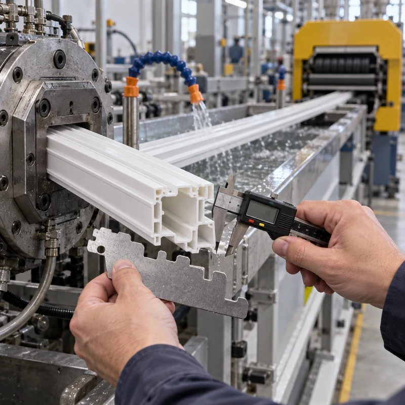
Plastic extrusion continuously pushes molten polymer through a shaped die, then cools and pulls the profile to size. The process is efficient for rails, seals, channels, tubes, trim, and structural profiles, but dimensional control depends on much more than the die opening.

A profile can leave the die near nominal and still twist, bow, shrink, or change wall thickness during cooling and pulling. This guide connects geometry, material, tooling, process settings, inspection, and downstream CNC work.

Quick Answer

Use balanced walls, generous transitions, realistic tolerances, and datums that can be measured consistently. Control melt temperature, output, cooling, puller speed, and material condition together. Prototype the cross-section before committing to long production runs.

Key Engineering Factors

Factor Practical effect Control method
Wall variation Uneven flow and cooling create distortion Keep thickness transitions gradual
Die swell Profile expands after leaving the die Compensate through tooling and stable process settings
Cooling Uneven shrink creates bow and twist Balance water, air, support, and line speed
Puller speed Changes section size and residual stress Monitor speed against output rate
Material lot Viscosity and shrinkage can vary Use controlled resin specifications and incoming checks

How Extrusion Tolerances Are Created

The finished dimension results from die geometry, melt rheology, pressure, drawdown, cooling shrinkage, calibration, haul-off speed, and residual stress. Tightening a drawing tolerance without changing the process does not create capability.

Cross-Section Design Rules

Balanced geometry promotes even flow and cooling. Thick masses cool slowly while thin walls freeze early, producing stress and distortion. Hollow chambers need webs and radii that allow material to divide and reunite without weak lines.

  • Keep nominal walls as uniform as function allows
  • Avoid abrupt heavy-to-thin transitions
  • Use radii instead of sharp internal corners
  • Provide enough support for thin fins and lips
  • Discuss hollow chambers and weld lines with the die maker

Datum and Tolerance Strategy

Dimension the profile from stable, functional surfaces. Do not chain every cross-section dimension when one datum scheme can control assembly. Separate critical fit dimensions from cosmetic or non-functional geometry.

  • Use profile or contour tolerances where appropriate
  • Specify bow and twist over a defined length
  • State measurement temperature and conditioning
  • Identify cut-length and end-squareness separately

Materials and Shrinkage

PVC, ABS, polycarbonate, polyethylene, polypropylene, nylon, TPE, and filled compounds behave differently. Fillers can reduce shrinkage but change surface, wear, and flow. Hygroscopic polymers require drying.

Cooling, Calibration, and Cutoff

Vacuum calibration can hold demanding external surfaces. Water temperature, spray distribution, support rollers, and puller alignment influence straightness. Cutoff adds length variation, burrs, and end deformation.

Inspection and Process Capability

Use gauges or optical systems for recurring cross-sections, and confirm results after the profile reaches stable temperature. Capability should be demonstrated over time, not inferred from one first sample.

  • Measure multiple positions across the run
  • Track key dimensions with process settings
  • Inspect bow, twist, surface, color, and cut ends
  • Retain approved samples and gauge methods

When CNC Secondary Operations Help

Drilling, milling, routing, tapping, and end machining can add accurate interfaces after extrusion. Fixtures must support the profile without crushing it, and datums should match the final assembly.

Frequently Asked Questions

What is a realistic extrusion tolerance?

It depends on material, section size, geometry, calibration, and measurement length. Ask the supplier for demonstrated capability on comparable profiles.

Why do extrusions twist?

Asymmetric walls, uneven cooling, off-center pull, residual stress, and material variation can all create twist.

Can extruded plastic be CNC machined?

Yes. CNC operations are common for holes, slots, pockets, threads, and precision ends when the part is supported correctly.
Related MTSPi CNC Resources

Categories
Blog Design, Cost & Sourcing Manufacturing Process Comparisons

Progressive Die Stamping: How to Know If It Fits Your Part

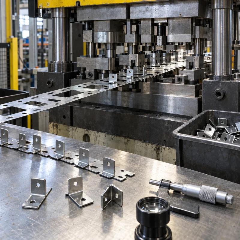
Progressive die stamping moves a continuous metal strip through a sequence of stations. Each press stroke performs operations such as piercing, trimming, coining, bending, drawing, and cutoff. Once the tool is proven, the process can produce complex sheet-metal parts at high speed and low unit cost.

The economic advantage depends on suitable geometry and enough stable volume to recover tooling investment. This guide shows how to decide whether a part belongs in a progressive die or should remain with laser cutting, forming, machining, or another process.

Quick Answer

Progressive die stamping fits repeatable sheet-metal parts with high annual volume, stable design, coil-compatible material, and features that can be formed through sequential stations. It is a poor fit for uncertain demand, frequent revisions, very low quantities, thick 3D geometry, or tolerances that require extensive secondary machining.

Key Differences at a Glance

Factor Option A Option B Engineering note
Volume High repeat demand Prototype or low demand Tooling payback drives the decision
Design stability Frozen geometry Frequent revisions Tool changes can be expensive
Geometry Sequential sheet operations Deep 3D machined features A feasible strip layout is essential
Unit cost Very low after launch Higher but flexible Include scrap and maintenance
Lead time Longer tooling launch Short setup Bridge production may be needed

How the Progressive Die Works

Stock uncoils and advances by a fixed pitch. Pilot features register the strip, while each station adds a controlled operation. The carrier keeps parts connected until cutoff. Strip layout determines material use, station count, force balance, progression, and tool size.

Best-Fit Part Characteristics

Good candidates are small to medium sheet-metal parts with repeated holes, tabs, forms, embosses, and bends. Terminals, clips, brackets, shields, contacts, and retainers are common examples.

  • Stable annual demand
  • Consistent coil material and thickness
  • Features that can be reached from the press direction
  • Tolerances compatible with stamping and springback
  • Sufficient web and carrier material

Design Factors That Control Feasibility

Hole-to-edge distance, bend radius, material grain, formed-feature spacing, burr direction, flatness, and springback all influence the tool. Very tight features may require shaving, coining, restriking, sensors, or secondary operations.

  • Use bend radii appropriate to the alloy and temper
  • Keep holes away from bend deformation zones
  • Identify burr direction when assembly or safety matters
  • Avoid unnecessary flatness across heavily formed parts
  • Define functional tolerances separately from general dimensions

Volume and Break-Even Analysis

Compare annual volume, expected product life, tool cost, material utilization, press rate, labor, maintenance, scrap, and secondary operations. A low stamped piece price does not justify a tool if demand may disappear before payback.

  • Model conservative and expected demand
  • Include tool modifications and spare details
  • Account for coil scrap and startup scrap
  • Compare bridge and backup processes
  • Review design-change risk before approval

Tooling, Sensors, and Maintenance

Progressive tools include punches, dies, pilots, lifters, strippers, guides, and forming inserts. Sensors can detect feed errors, part ejection, buckle, or stock position. Preventive maintenance protects dimensional stability and avoids damage that can affect every station.

Quality Planning

Inspection should focus on dimensions that can drift through punch wear, springback, strip feed, and material variation. Optical inspection, gauges, CMM checks, and in-die monitoring may be combined depending on risk.

  • Approve strip and finished-part samples
  • Track tool wear on critical punches
  • Control coil width, thickness, hardness, and grain
  • Use capability studies for key dimensions
  • Define reaction plans for sensor alarms

Alternatives to Progressive Stamping

Laser cutting and press-brake forming suit prototypes and changing designs. CNC machining suits thick or three-dimensional precision parts. Compound or transfer dies may fit different geometries and volumes. A staged route can use soft tooling before progressive production.

Frequently Asked Questions

What volume justifies a progressive die?

There is no universal threshold. Calculate payback using tool cost, expected lifetime demand, unit savings, scrap, maintenance, and design-change risk.

Can tight tolerances be stamped?

Yes for selected features with appropriate tool design and process control, but CNC-level tolerances everywhere can make the tool unnecessarily complex and expensive.

Can a progressive stamped part be machined afterward?

Yes. Secondary CNC operations can add precision holes, threads, flat sealing faces, or interfaces that are not economical to hold in the die.

Related MTSPi CNC Resources

Categories
Blog Design, Cost & Sourcing Manufacturing Process Comparisons

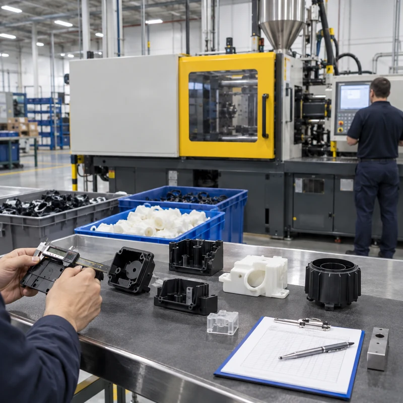
Low-Volume Injection Molding Companies: How to Choose a Fast, Reliable Supplier

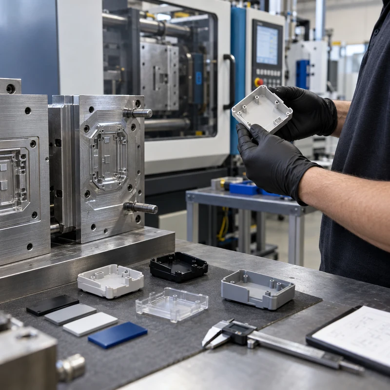
Low-volume injection molding fills the gap between prototypes and stable mass production. It can supply pilot builds, bridge production, market tests, service parts, regulated validation lots, and products with modest lifetime demand. The supplier must optimize for change, speed, and risk rather than only maximum press utilization.

This guide explains how to compare low-volume injection molding companies using evidence that affects your actual program: tooling approach, DFM, resin experience, dimensional control, revision handling, capacity, and total cost.

Quick Answer

Choose a supplier that matches your volume and uncertainty. Aluminum or simplified steel tooling can shorten lead time, but tooling decisions must still support resin temperature, surface finish, tolerances, expected shots, and future changes. Validate geometry before hardening the supply chain.

Key Differences at a Glance

Factor Option A Option B Engineering note
Tool objective Fast bridge or prototype mold Long-life production mold Choose around lifetime shots and revision risk
Typical flexibility High Lower after completion Early programs benefit from replaceable inserts
Automation Selective Often extensive Do not pay for automation without volume
Validation Fit-for-purpose Full production qualification Regulatory needs may require either
Unit cost Higher Lower at volume Compare total program cost

Define Low Volume Before Requesting Quotes

Low volume may mean dozens of parts for one company and tens of thousands for another. State annual demand, lot size, product life, launch date, and demand uncertainty. Include expected resin, color, cosmetic class, tolerances, and secondary operations.

Tooling Strategies

Prototype molds may use aluminum, pre-hardened steel, modular bases, manual inserts, or single-cavity layouts. Each choice trades tooling cost against cycle time, life, maintenance, finish, and repeatability.

  • Ask who owns the mold and CAD data
  • Confirm expected tool life and maintenance
  • Define included sampling rounds
  • Clarify transfer rights and compatible press base
  • Use replaceable inserts for likely design changes

DFM and Mold-Flow Review

A supplier should review draft, wall thickness, ribs, bosses, undercuts, gate location, weld lines, venting, cooling, shrinkage, and ejection. A quote with no engineering questions may simply defer risk until the first sample.

  • Use uniform walls where practical
  • Keep ribs thinner than adjacent walls
  • Provide draft based on texture and depth
  • Protect cosmetic surfaces from gates and ejectors
  • Identify dimensions that truly control function

Quality and First-Article Approval

Low quantity does not eliminate the need for a stable process. Define an inspection plan and approval sample. For critical dimensions, ask how variation across cavities, cycles, resin lots, and environmental conditions will be controlled.

  • Material certificates and lot traceability
  • First Article Inspection
  • Color and cosmetic limit samples
  • Gauge strategy for recurring lots
  • Documented process settings and change control

Lead Time and Capacity

Fast tooling is useful only if the supplier also has press time, resin, secondary operations, and inspection capacity. Ask for a schedule from DFM approval through tool build, T1 sample, revisions, validation, and production release.

CNC Prototypes Before Molding

CNC machining can validate production-intent material, fasteners, sealing surfaces, flatness, and interfaces before mold steel is cut. It is particularly useful when a late dimensional change would require welding and re-machining a mold insert.

  • Prototype high-risk interfaces first
  • Use the same controlled drawing revision
  • Record assembly findings
  • Update both CAD and inspection plan before tooling

Supplier Red Flags

Warning signs include vague tool ownership, no discussion of resin drying or shrinkage, unrealistic lead time without a schedule, weak change control, and an inability to explain how critical dimensions will be measured.

Frequently Asked Questions

What quantity suits low-volume injection molding?

It depends on part size, tool complexity, and economics. Programs can range from hundreds to tens of thousands of parts; compare molding with CNC, urethane casting, and additive manufacturing using total program cost.

Is aluminum tooling suitable?

Often yes for prototype and bridge programs, but abrasive or high-temperature resins, complex slides, tight cosmetics, and long life may justify steel.

How can tooling risk be reduced?

Complete DFM, prototype critical features, identify likely revisions, use modular inserts where practical, and define sample approval before production.

Related MTSPi CNC Resources

Categories
Blog Design, Cost & Sourcing Manufacturing Process Comparisons

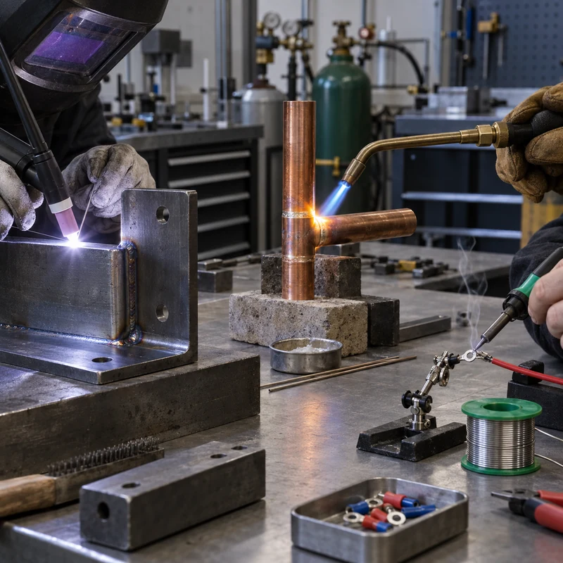
Brazing vs Welding vs Soldering: Key Differences for Metal Assemblies

Brazing, welding, and soldering all create permanent joints, but they do so through different thermal and metallurgical mechanisms. The correct choice depends on load, service temperature, base materials, joint clearance, distortion limits, appearance, production volume, and whether precision-machined features must remain stable.

This guide compares the three processes from a practical design and sourcing perspective, including how each one interacts with CNC-machined components and final inspection.

Quick Answer

Welding melts the base materials and generally provides the strongest structural joint. Brazing melts a filler above 450°C without melting the base parts and works well for dissimilar metals, thin sections, and capillary joints. Soldering uses lower-temperature filler and is best for electronics, terminals, and lightly loaded assemblies.

Key Differences at a Glance

Factor Option A Option B Engineering note
Base metal Melted in welding Not melted in brazing or soldering Heat input changes distortion and properties
Typical strength Highest structural potential Moderate to high with correct joint Low to moderate Strength must match actual service load
Temperature Highest Intermediate Lowest Affects coatings, seals, and heat treatment
Joint fit Gap and preparation depend on weld Close clearance supports capillary flow Clean close contact preferred Do not apply machining tolerances blindly
Dissimilar metals Sometimes difficult Often practical Common in electrical work Check galvanic corrosion and filler compatibility

How Each Process Creates a Joint

Welding forms a local molten pool from the base materials, usually with optional filler. Brazing and soldering rely on a separate filler that wets prepared surfaces and flows into the joint. Because the base parts remain solid during brazing and soldering, dimensional change can be lower, but surface cleanliness and joint clearance become critical.

When Welding Is the Better Choice

Use welding for frames, brackets, pressure structures, heavy loads, and assemblies where the joint must approach the strength of the parent material. MIG supports productive fabrication; TIG provides controlled high-quality joints; laser welding can reduce the heat-affected zone when fit-up is excellent.

  • Provide torch access and fixture locations
  • Keep precision datums away from the weld zone
  • Machine sealing faces and critical bores after welding
  • Specify weld standard, size, length, contour, and inspection

When Brazing Is Better

Brazing is useful for joining dissimilar metals, thin-wall components, carbide tools, copper assemblies, and complex joints where filler can flow by capillary action. Lap area often matters more than a large visible bead. A controlled gap helps filler flow and prevents weak, filler-starved joints.

  • Select filler for both metals and service temperature
  • Design overlap and clearance for the chosen alloy
  • Provide vent paths for blind cavities
  • Remove flux residue when corrosion or cleanliness matters

When Soldering Is Better

Soldering is primarily used for electrical and electronic connections, small terminals, sensors, and low-load joints. It minimizes thermal damage compared with welding, but it is not a substitute for a structural joint. Mechanical strain relief should carry cable and vibration loads.

Distortion, Finish, and CNC Planning

Heat can move holes, flattening surfaces, and bearing seats. Establish whether drawing dimensions apply before or after joining. Rough-machine first when needed, join in a controlled fixture, stress-relieve if required, then finish-machine the functional interfaces.

  • Add machining allowance on post-joined surfaces
  • Use datums that survive the joining cycle
  • Protect threads and finished surfaces from spatter and flux
  • Inspect both joint quality and final geometry

Cost and Quality Checklist

Total cost includes preparation, filler, shielding or flux, fixtures, cycle time, cleanup, heat treatment, finishing, inspection, and rework risk. Choose the least complex process that safely meets the functional requirement.

  • State base metals and material condition
  • Define service load and temperature
  • Identify leak, electrical, cosmetic, and corrosion requirements
  • Approve representative samples before production

Frequently Asked Questions

Is brazing as strong as welding?

A well-designed brazed lap joint can be strong, but welding is normally preferred for highly loaded structural joints. Compare joint geometry and service conditions rather than filler strength alone.

Can aluminum be brazed or soldered?

Yes, with compatible filler, flux, surface preparation, and temperature control. Aluminum oxide makes wetting difficult, so the process must be designed specifically for aluminum.

Should precision holes be machined before joining?

Rough features may be created first, but tight bores and datums are often finished after a high-heat operation to remove distortion.

Related MTSPi CNC Resources

Categories
Blog CNC Materials Guides Manufacturing Process Comparisons

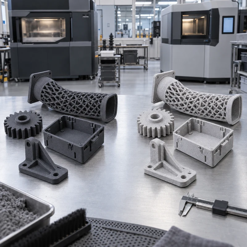
MJF vs SLS: Choosing the Right Nylon 3D Printing Process for Functional Parts

MJF and SLS both build nylon parts inside a powder bed without conventional support structures. That makes both processes useful for complex ducts, housings, clips, brackets, living hinges, lattice features, and low-volume assemblies. The practical differences appear in heat delivery, surface character, dimensional behavior, color, nesting strategy, and supplier workflow.

This MJF vs SLS guide explains those differences for engineers who need functional parts, not just visual models.

Quick Answer

Choose MJF when you want consistent mechanical behavior, fine detail, relatively uniform surfaces, and efficient batches of PA12 parts, especially when dark gray or dyed black is acceptable. Choose SLS when you need broad material availability, flexible build sizes, proven nylon options, or a supplier ecosystem suited to varied quantities and geometries. Test the actual material and orientation when fatigue, snap fits, pressure, or heat matters.

How MJF and SLS Work

SLS scans a laser across each powder layer and sinters the selected cross-section. MJF deposits fusing and detailing agents across the layer, then applies thermal energy. In both methods, surrounding powder supports the part, allowing nested builds and complex shapes without the support marks associated with many resin or filament processes.

MJF vs SLS Comparison

Factor MJF SLS
Energy delivery Fusing agents plus thermal energy Laser scans each cross-section
Typical appearance Graphite gray, often dyed black Natural white or light gray, easily dyed
Surface Fine, relatively uniform powder texture Slightly grainier texture depending on machine
Materials Strong focus on PA12 and selected polymers Broad nylon and specialty-powder ecosystem
Mechanical consistency Often relatively uniform in common PA12 builds Good but orientation and machine still matter
Supports Not normally required Not normally required
Best fit Functional batches and detailed PA12 parts Flexible materials, sizes, and established applications

Material Options

PA12 is the most common comparison material because it balances toughness, stiffness, chemical resistance, and dimensional stability. PA11 offers greater ductility for impact and snap features. Glass-filled nylons increase stiffness but can become less forgiving and more abrasive. TPU-like powders support flexible components, though machine availability and tolerances differ.

Always compare datasheets for the exact machine-material combination. A generic label such as “nylon” is not enough for a load-bearing design.

Accuracy and Dimensional Control

Both processes are suitable for functional prototypes, but neither should be treated like precision CNC machining. Large flat surfaces can warp, thin walls can move, and holes may print undersize. Geometry, orientation, cooling, packing density, and refresh ratio affect results.

  • Add clearance to mating printed parts instead of using nominal CAD fits.
  • Avoid very large unsupported flat panels; use ribs or gentle curvature.
  • Use consistent wall thickness and gradual transitions.
  • Machine or ream critical bores after printing when required.
  • Validate snap fits using the intended material, finish, and orientation.

Surface Finish, Color, and Sealing

Both processes leave a matte powder texture. Bead blasting creates a more uniform appearance. Dyeing is common, especially black. Tumbling or chemical smoothing can improve feel and cleanability but may soften small edges or change dimensions. Unsealed nylon remains somewhat porous, so pressure, fluid, and hygiene applications may need infiltration, coating, or a different process.

Strength and Functional Testing

Printed PA12 can support clips, ducts, covers, fixtures, and many load-bearing prototypes. However, long-term creep, fatigue, temperature, moisture, and chemicals should be considered. Use application loads rather than a single tensile value. Test thin hinges, snap arms, screw bosses, and press fits because these features concentrate strain.

Cost and Lead-Time Drivers

Driver Why it matters
Bounding box Controls how efficiently parts nest in the build
Build height Adds layers and machine time
Part quantity Dense nesting can lower unit cost
Powder refresh Material handling affects operating cost
Cooling Parts may remain in the build for controlled cooling
Finishing Blasting, dyeing, smoothing, and sealing add steps
Inspection Critical dimensions and lot records add labor

Design Recommendations

  • Use ribs and radii to support thin functional structures.
  • Keep escape openings large enough to remove powder from channels.
  • Do not create trapped cavities unless powder retention is acceptable.
  • Use threaded inserts for repeated assembly rather than relying on printed threads.
  • Separate cosmetic and critical dimensional surfaces on the drawing.
  • Mark surfaces that will be machined and provide stock where needed.

When CNC Machining Is the Better Choice

CNC machining is often better when the part needs a specific engineering plastic grade, tight hole or datum tolerances, low surface roughness, transparent material, stable flatness, or traceable stock properties. Printed nylon is excellent for geometry and low-volume function; machined nylon, POM, PEEK, aluminum, or other production materials may be better for final validation.

A Practical Selection Checklist

  • What exact polymer grade is required?
  • Which dimensions control assembly?
  • Will the part see fatigue, heat, moisture, pressure, or chemicals?
  • Does color or surface feel matter?
  • Can all trapped powder be removed?
  • Is the quantity high enough to benefit from dense nesting?
  • Should critical features be CNC finished?

Frequently Asked Questions

Is MJF stronger than SLS?

There is no universal answer. With comparable PA12, MJF often provides consistent properties, but machine settings, orientation, geometry, and finishing matter. Use supplier data and functional testing for critical parts.

Which process gives a smoother surface?

MJF often appears finer and more uniform, while SLS can feel slightly grainier. Both remain matte and benefit from blasting, dyeing, or smoothing when appearance matters.

Can MJF or SLS parts be CNC machined?

Yes. Printed parts can be drilled, tapped, reamed, milled, or fitted with inserts, provided the fixture supports the part and the design includes enough material around the feature.

Related MTSPi CNC Resources

Categories
Blog CNC Materials Guides Manufacturing Process Comparisons

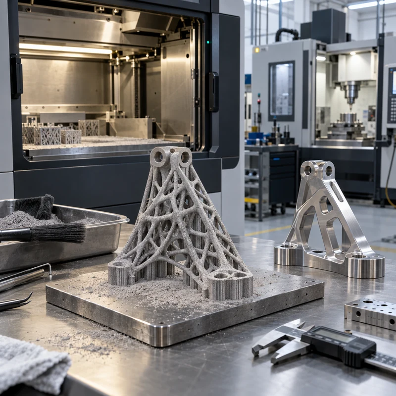
Metal 3D Printing Guide: Processes, Materials, Applications, and CNC Post-Processing

Metal 3D printing creates shapes that are difficult or impossible to machine from solid stock, including internal channels, lattice structures, consolidated assemblies, and topology-optimized parts. It is not a universal replacement for CNC machining. Printed parts commonly require support removal, heat treatment, surface finishing, dimensional inspection, and machining of critical features.

This guide compares the main metal additive processes and explains how to plan a complete production route rather than judging only the printing step.

Metal 3D Printing at a Glance

Process How it works Strength Typical fit
SLM/DMLS Laser fuses metal powder in a bed High after correct processing Complex precision parts and low volumes
EBM Electron beam melts powder in vacuum High Titanium and high-temperature applications
Binder jetting Binder shapes powder before sintering Process-dependent Higher throughput and smaller parts
DED Powder or wire is fed into an energy source High with controlled parameters Repair, cladding, and large near-net shapes

SLM and DMLS

Powder-bed fusion spreads a thin metal powder layer and selectively fuses each cross-section. The method supports complex geometry and fine features, but build orientation, supports, residual stress, powder removal, and scan strategy all affect the result. The terms SLM and DMLS are often used commercially for closely related laser powder-bed processes; the exact machine, material specification, and qualification route matter more than the label.

Electron Beam Melting

EBM uses an electron beam in a vacuum and maintains an elevated build temperature. It is strongly associated with titanium applications. The process can reduce some residual-stress concerns, but surfaces are generally rougher and dimensional finishing may still be required.

Binder Jetting

Binder jetting forms a fragile green part that is later debound and sintered. It can deliver higher throughput because the printhead works across the bed, but sintering shrinkage must be predicted and controlled. Density, distortion, feature size, and material-property requirements determine whether it is appropriate.

Directed Energy Deposition

DED feeds powder or wire into a melt pool. It is useful for adding material to existing components, repairing expensive parts, applying wear-resistant material, and producing large near-net preforms. Resolution is lower than powder-bed fusion, so machining is usually part of the route.

Common Metal Materials

Material Why it is printed Typical post-processing concern
316L stainless steel Corrosion resistance and broad usability Support removal and sealing surfaces
17-4PH stainless steel Strength after heat treatment Heat-treatment condition and final dimensions
AlSi10Mg aluminum Low mass and good printability Porosity, heat treatment, threaded features
Ti-6Al-4V High strength-to-weight ratio Oxygen control, fatigue surface, cost
Inconel alloys High-temperature performance Machining difficulty and residual stress
Cobalt chrome Wear and biomedical applications Qualification and finishing

Design Rules for Printable Metal Parts

  • Use additive geometry only where it creates measurable value.
  • Orient critical surfaces to balance supports, distortion, finish, and build time.
  • Provide escape paths for trapped powder in internal channels.
  • Add machining stock to bores, datums, threads, gasket faces, and bearing seats.
  • Avoid unsupported down-facing surfaces that create roughness or collapse risk.
  • Use gradual transitions to reduce local heat accumulation.
  • Design reference features that can be located during CNC finishing and inspection.

Accuracy, Surface Finish, and Porosity

As-printed accuracy is affected by machine calibration, thermal distortion, orientation, feature size, support strategy, and material. Surface texture varies by upward, vertical, and downward-facing orientation. Internal porosity and lack-of-fusion defects require process control and may require CT scanning or destructive validation for high-consequence parts.

Do not assign CNC-level tolerances to every printed surface. Separate additive surfaces from features that will be machined. This creates a realistic drawing and prevents unnecessary cost.

Why CNC Post-Processing Matters

CNC machining provides repeatable datums and functional interfaces after printing. A typical sequence can include stress relief, separation from the build plate, support removal, rough inspection, heat treatment or hot isostatic pressing, fixture preparation, CNC finishing, deburring, surface treatment, and final inspection.

The fixture plan must account for irregular printed surfaces. Purpose-designed sacrificial pads, cylinders, or tabs can give the machining setup reliable locating and clamping features, then be removed in a later operation.

Cost Drivers

  • Build volume and height, not just part weight.
  • Support material and support-removal labor.
  • Machine occupancy and number of parts nested in a build.
  • Powder type, reuse rules, and traceability.
  • Heat treatment, HIP, testing, and certification.
  • CNC setups, custom fixtures, and inspection.
  • Failed-build risk and qualification samples.

When to Choose Metal Printing, CNC, or a Hybrid Route

Choose metal printing for valuable geometric complexity, internal flow paths, mass reduction, consolidation, or very low-volume shapes. Choose CNC machining for prismatic or rotational parts, predictable tolerances, smooth surfaces, standard materials, and straightforward low-volume production. Use a hybrid route when the printed geometry creates value but interfaces still require precision.

Frequently Asked Questions

Are metal 3D printed parts fully dense?

Qualified powder-bed processes can achieve very high density, but density alone does not prove fatigue performance or absence of critical defects. Process qualification and application-specific testing remain important.

Can threads be printed directly?

Large non-critical threads may be printable, but tapped or CNC-machined threads are generally more predictable for assembly, gauges, sealing, and repeated use.

What should be included on the drawing?

Identify the additive process and material specification, post-processing condition, machined surfaces, datums, critical tolerances, inspection method, surface finish, and any qualification requirements.

Related MTSPi CNC Resources

Categories
Blog Design, Cost & Sourcing Manufacturing Process Comparisons

How to Evaluate Injection Molding Companies in the USA: A 2026 Supplier Guide

Searching for injection molding companies in the USA produces long lists, but a supplier’s location or machine count does not show whether it fits your part. The useful question is whether its tooling, process control, material experience, quality system, capacity, communication, and commercial model match your program.

This guide provides a repeatable selection method for product teams. It does not rank companies by marketing visibility. Instead, it shows how to build a shortlist and compare evidence before committing to tooling.

Quick Supplier Selection Framework

Start with the part and program, not the supplier list. Define annual volume, resin, part size, cosmetic class, tolerance, regulatory needs, assembly content, target launch, and expected design changes. Eliminate suppliers that cannot support the required press size, resin family, documentation, or validation. Audit the remaining candidates using the same scorecard.

Eight Criteria That Matter Most

Criterion Evidence to request Risk if ignored
Tooling capability Mold design review, toolroom scope, maintenance plan Slow changes and recurring defects
Material experience Similar resin examples and drying controls Warp, splay, brittleness, color variation
Process control Documented windows and setup records Lot-to-lot inconsistency
Quality system Inspection plan, calibration, traceability Undetected defects and weak containment
Capacity Press availability and contingency plan Launch or replenishment delays
Engineering support DFM examples and mold-flow capability Tooling that locks in avoidable problems
Secondary operations Assembly, inserts, decorating, packaging Extra suppliers and handling risk
Commercial fit Transparent tooling ownership and change terms Unexpected fees and difficult transfers

Match the Supplier to Your Production Stage

A prototype or bridge program values speed, flexible tooling, and frequent engineering communication. A stable high-volume program values automation, cavity efficiency, preventive maintenance, material purchasing leverage, and dependable replenishment. A regulated program adds validation, traceability, change control, and record retention.

One supplier may be excellent at complex medical molding but expensive for a simple industrial housing. Another may run commodity resins efficiently but lack the engineering depth for optical parts or tight-tolerance inserts. Capability must be evaluated against the actual part family.

Tooling Questions to Ask Before Purchase

  • Who owns the mold, CAD data, and spare components?
  • Where will the mold be built, sampled, maintained, and stored?
  • What steel, insert, hot-runner, cooling, venting, and ejection approach is proposed?
  • How many shots is the quoted tool expected to support?
  • What is included in the sampling and approval cycle?
  • How are engineering changes priced and documented?
  • Can the mold be transferred, and is it compatible with another press base?

Quality and Validation

Request a control plan that links drawing requirements to measurement methods and sampling frequency. Critical dimensions may need a capability study. Cosmetic surfaces need an approved limit sample and controlled lighting. Materials may require certificates, lot traceability, moisture control, or regulatory declarations.

First Article Inspection is useful, but it is not the entire validation. A few acceptable parts do not prove a stable process. Ask how the supplier establishes the molding window and verifies performance across normal material, machine, cavity, and environmental variation.

Total Cost Beyond Piece Price

Cost component What to compare
Tooling Build, samples, spares, maintenance, modifications
Unit cost Resin, cycle time, cavities, labor, scrap
Quality Inspection, validation, containment, returns
Logistics Freight, packaging, inventory, emergency shipments
Change risk Revision speed and cost before design freeze
Program support Engineering time, reporting, communication

When a Hybrid Supply Chain Makes Sense

Some teams combine US molding with overseas tooling, CNC prototypes, or low-volume bridge production. This can balance response time and cost, but only when ownership, tolerances, data exchange, and responsibility are explicit. Before cutting a production mold, CNC-machined or printed prototypes can verify assembly, ergonomics, fastener access, and major dimensions.

Red Flags During Supplier Review

  • A quote arrives with no questions about draft, wall thickness, gate location, resin, or tolerance.
  • The supplier cannot explain how critical dimensions will be controlled.
  • Tool ownership and transfer terms are vague.
  • Every defect is treated as an inspection problem rather than a process problem.
  • Capacity claims are not supported by a launch or contingency plan.
  • Communication changes after the purchase order is issued.

Practical RFQ Package

Send a clean 3D model, controlled 2D drawing, expected volumes, resin specification, color and cosmetic standard, mating-part information, packaging needs, validation level, and launch schedule. Identify must-have requirements separately from preferences. This gives each supplier the same basis and makes quotations easier to compare.

Frequently Asked Questions

Should I choose the lowest injection molding quote?

Not automatically. Compare the included tool construction, sample cycles, process validation, maintenance, quality controls, logistics, and change terms. A low quote with weak assumptions can create a higher total program cost.

How many suppliers should receive an RFQ?

Three to five qualified suppliers is usually enough for a meaningful comparison. A very broad RFQ can consume time without improving the decision if candidates have not been screened for fit.

Can CNC machining reduce injection molding risk?

Yes. CNC prototypes in production-intent material can validate geometry, assembly, threads, flatness, and interfaces before mold steel is committed.

Related MTSPi CNC Resources

Categories
Blog Guides Manufacturing Process Comparisons

SLA vs DLP Resin 3D Printing: Accuracy, Surface Finish, and Prototype Selection

SLA vs DLP Resin 3D Printing: Accuracy, Surface Finish, and Prototype Selection is a practical manufacturing question because the answer affects cost, lead time, material behavior, inspection, and the path from prototype to production. For MTSPi CNC customers, the key is not simply naming a process, but understanding how the process connects with machined parts, fixtures, tolerances, surface requirements, and final assembly.

This guide explains SLA vs DLP from an engineering and purchasing point of view. It is written for product developers, mechanical engineers, sourcing teams, and buyers who need clear decisions rather than generic process descriptions.

Quick Answer

Choose SLA or DLP based on part size, detail, surface finish, resin choice, and throughput. For final functional validation, compare printed resin limitations with CNC machined plastics or metals before approving the design.

Key Differences at a Glance

Point Option A Option B
Light method Laser traces each layer Projected image cures a layer
Speed Depends on scan length and geometry Often fast for full-layer exposure
Detail Very fine details possible Pixel size affects edge detail
Surface Smooth resin finish Smooth, sometimes pixel-related texture
Best use High-detail prototypes and appearance models Fast resin prototypes and small batches

How the Process Choice Affects Real Parts

A manufacturing method should be selected around the feature that actually controls function. Cosmetic surfaces, hidden support features, threads, bores, sealing faces, heat-transfer areas, and assembly datums do not carry the same risk. When those requirements are mixed together without priority, quotes become inconsistent and production becomes harder to control.

The safest workflow is to define the part requirement first, then match the process. A printed prototype may answer shape questions, a molded sample may answer appearance questions, and a CNC machined sample may answer tolerance, material, and functional questions. Many successful projects use more than one method before the final design is locked.

Design and Manufacturing Considerations

  • Use resin printing for appearance, fine detail, and early fit review.
  • Avoid assuming printed resin equals production ABS, nylon, aluminum, or steel.
  • Plan supports on non-critical surfaces when appearance matters.
  • Check thin walls and small pins against the printer and resin capability.
  • Use CNC machining for final material and tolerance validation.

Cost, Lead Time, and Risk Factors

Cost is driven by setup, tooling, material, machine time, inspection, finishing, and revision risk. A low unit price is not always the lowest project cost if it creates rework later. For prototypes and low-volume orders, flexibility can be more valuable than a process with a lower theoretical unit cost.

  • Use standard materials and standard feature sizes when they do not weaken the design.
  • Separate critical tolerances from general dimensions so the supplier knows where to focus.
  • Confirm surface finish and cosmetic requirements before production begins.
  • Avoid late changes to mounting holes, connector openings, datum faces, and threaded features.
  • Send CAD files and 2D drawings together when tolerances, threads, or finishes matter.

Quality Checks Before Production

A good quality plan checks the features that influence assembly and performance. Depending on the part, this may include dimensional inspection, thread gauges, surface roughness, flatness, perpendicularity, burr control, coating thickness, visual appearance, and fit with mating parts.

When This Topic Matters for CNC Buyers

SLA vs DLP matters when a team is comparing prototype routes, validating a design, replacing a weak supplier, or trying to reduce manufacturing cost without damaging function. The best choice is usually the process that answers the current engineering question with the least unnecessary risk.

MTSPi CNC Engineering Notes

MTSPi CNC supports precision CNC milling, turning, rapid prototyping, low-volume production, finishing, and inspection for custom parts. If your project uses molding, casting, welding, PCB assemblies, or 3D printing, CNC machining can still be important for datums, holes, threads, sealing faces, fixtures, and production-ready prototypes.

Frequently Asked Questions

Can this process replace CNC machining?

Sometimes it can replace CNC for non-critical geometry, but CNC is often still needed when tight tolerances, real engineering material, threads, flat sealing faces, or precise mating features are required.

What files help MTSPi CNC review a project?

STEP or STP files are useful for geometry. A 2D drawing is important for tolerances, materials, threads, surface finish, inspection requirements, and notes that are not obvious from the CAD model.

How do I reduce manufacturing risk?

Define critical features, avoid unnecessary tight tolerances, confirm material and finish requirements, and use prototypes to validate assembly before committing to higher-volume tooling or production.

Related MTSPi Resources

Categories
Blog Guides Manufacturing Process Comparisons

SLA vs FDM 3D Printing: Choosing the Right Prototype Before CNC Machining

SLA vs FDM 3D Printing: Choosing the Right Prototype Before CNC Machining is a practical manufacturing question because the answer affects cost, lead time, material behavior, inspection, and the path from prototype to production. For MTSPi CNC customers, the key is not simply naming a process, but understanding how the process connects with machined parts, fixtures, tolerances, surface requirements, and final assembly.

This guide explains SLA vs FDM from an engineering and purchasing point of view. It is written for product developers, mechanical engineers, sourcing teams, and buyers who need clear decisions rather than generic process descriptions.

Quick Answer

Choose SLA for smooth visual models and fine details. Choose FDM for quick, low-cost functional mockups, larger prototypes, and early fit checks. Move to CNC machining when the prototype must match production material, tolerance, surface finish, or strength.

Key Differences at a Glance

Point Option A Option B
Material Photopolymer resin Thermoplastic filament
Surface finish Smooth and detailed Visible layer lines
Strength Resin-dependent, sometimes brittle Better for basic functional handling
Cost Moderate, depends on resin and finishing Usually low for early prototypes
Best use Appearance, fine detail, small features Fit checks, fixtures, larger simple forms

How the Process Choice Affects Real Parts

A manufacturing method should be selected around the feature that actually controls function. Cosmetic surfaces, hidden support features, threads, bores, sealing faces, heat-transfer areas, and assembly datums do not carry the same risk. When those requirements are mixed together without priority, quotes become inconsistent and production becomes harder to control.

The safest workflow is to define the part requirement first, then match the process. A printed prototype may answer shape questions, a molded sample may answer appearance questions, and a CNC machined sample may answer tolerance, material, and functional questions. Many successful projects use more than one method before the final design is locked.

Design and Manufacturing Considerations

  • Use SLA when small details or smooth surfaces drive the review.
  • Use FDM when speed, size, and basic function matter more than appearance.
  • Do not validate tight production tolerances with low-resolution printed parts.
  • Prototype threaded or snap-fit features carefully because printed behavior differs from machined or molded parts.
  • Move critical functional tests to CNC or production-equivalent processes.

Cost, Lead Time, and Risk Factors

Cost is driven by setup, tooling, material, machine time, inspection, finishing, and revision risk. A low unit price is not always the lowest project cost if it creates rework later. For prototypes and low-volume orders, flexibility can be more valuable than a process with a lower theoretical unit cost.

  • Use standard materials and standard feature sizes when they do not weaken the design.
  • Separate critical tolerances from general dimensions so the supplier knows where to focus.
  • Confirm surface finish and cosmetic requirements before production begins.
  • Avoid late changes to mounting holes, connector openings, datum faces, and threaded features.
  • Send CAD files and 2D drawings together when tolerances, threads, or finishes matter.

Quality Checks Before Production

A good quality plan checks the features that influence assembly and performance. Depending on the part, this may include dimensional inspection, thread gauges, surface roughness, flatness, perpendicularity, burr control, coating thickness, visual appearance, and fit with mating parts.

When This Topic Matters for CNC Buyers

SLA vs FDM matters when a team is comparing prototype routes, validating a design, replacing a weak supplier, or trying to reduce manufacturing cost without damaging function. The best choice is usually the process that answers the current engineering question with the least unnecessary risk.

MTSPi CNC Engineering Notes

MTSPi CNC supports precision CNC milling, turning, rapid prototyping, low-volume production, finishing, and inspection for custom parts. If your project uses molding, casting, welding, PCB assemblies, or 3D printing, CNC machining can still be important for datums, holes, threads, sealing faces, fixtures, and production-ready prototypes.

Frequently Asked Questions

Can this process replace CNC machining?

Sometimes it can replace CNC for non-critical geometry, but CNC is often still needed when tight tolerances, real engineering material, threads, flat sealing faces, or precise mating features are required.

What files help MTSPi CNC review a project?

STEP or STP files are useful for geometry. A 2D drawing is important for tolerances, materials, threads, surface finish, inspection requirements, and notes that are not obvious from the CAD model.

How do I reduce manufacturing risk?

Define critical features, avoid unnecessary tight tolerances, confirm material and finish requirements, and use prototypes to validate assembly before committing to higher-volume tooling or production.

Related MTSPi Resources

Categories
Blog Design, Cost & Sourcing Manufacturing Process Comparisons

What Is Welding? Process Basics, Joint Types, and Machined-Part Design Notes

What Is Welding? Process Basics, Joint Types, and Machined-Part Design Notes is a practical manufacturing question because the answer affects cost, lead time, material behavior, inspection, and the path from prototype to production. For MTSPi CNC customers, the key is not simply naming a process, but understanding how the process connects with machined parts, fixtures, tolerances, surface requirements, and final assembly.

This guide explains what is welding from an engineering and purchasing point of view. It is written for product developers, mechanical engineers, sourcing teams, and buyers who need clear decisions rather than generic process descriptions.

Quick Answer

Welding is best for joining fabricated structures and metal assemblies. If a surface must remain flat, round, sealed, or tightly located, plan post-weld CNC machining or use a design that protects precision features from heat distortion.

Key Differences at a Glance

Point Option A Option B
MIG welding General fabrication and production assemblies Spatter, heat input, distortion
TIG welding Precise welds and thin materials Slower speed, operator skill
Spot welding Sheet metal overlap joints Access to both sides
Laser welding Small, precise, lower heat input joints Joint fit-up and equipment cost
Resistance welding High-volume sheet assemblies Material and thickness limits

How the Process Choice Affects Real Parts

A manufacturing method should be selected around the feature that actually controls function. Cosmetic surfaces, hidden support features, threads, bores, sealing faces, heat-transfer areas, and assembly datums do not carry the same risk. When those requirements are mixed together without priority, quotes become inconsistent and production becomes harder to control.

The safest workflow is to define the part requirement first, then match the process. A printed prototype may answer shape questions, a molded sample may answer appearance questions, and a CNC machined sample may answer tolerance, material, and functional questions. Many successful projects use more than one method before the final design is locked.

Design and Manufacturing Considerations

  • Place precision datums away from weld beads when possible.
  • Use tabs, slots, fixtures, or pilot features to control assembly location.
  • Allow access for the torch, electrode, or laser path.
  • Specify weld size and location clearly instead of using vague notes.
  • Plan post-weld machining for sealing faces, bearing seats, and critical holes.

Cost, Lead Time, and Risk Factors

Cost is driven by setup, tooling, material, machine time, inspection, finishing, and revision risk. A low unit price is not always the lowest project cost if it creates rework later. For prototypes and low-volume orders, flexibility can be more valuable than a process with a lower theoretical unit cost.

  • Use standard materials and standard feature sizes when they do not weaken the design.
  • Separate critical tolerances from general dimensions so the supplier knows where to focus.
  • Confirm surface finish and cosmetic requirements before production begins.
  • Avoid late changes to mounting holes, connector openings, datum faces, and threaded features.
  • Send CAD files and 2D drawings together when tolerances, threads, or finishes matter.

Quality Checks Before Production

A good quality plan checks the features that influence assembly and performance. Depending on the part, this may include dimensional inspection, thread gauges, surface roughness, flatness, perpendicularity, burr control, coating thickness, visual appearance, and fit with mating parts.

When This Topic Matters for CNC Buyers

what is welding matters when a team is comparing prototype routes, validating a design, replacing a weak supplier, or trying to reduce manufacturing cost without damaging function. The best choice is usually the process that answers the current engineering question with the least unnecessary risk.

MTSPi CNC Engineering Notes

MTSPi CNC supports precision CNC milling, turning, rapid prototyping, low-volume production, finishing, and inspection for custom parts. If your project uses molding, casting, welding, PCB assemblies, or 3D printing, CNC machining can still be important for datums, holes, threads, sealing faces, fixtures, and production-ready prototypes.

Frequently Asked Questions

Can this process replace CNC machining?

Sometimes it can replace CNC for non-critical geometry, but CNC is often still needed when tight tolerances, real engineering material, threads, flat sealing faces, or precise mating features are required.

What files help MTSPi CNC review a project?

STEP or STP files are useful for geometry. A 2D drawing is important for tolerances, materials, threads, surface finish, inspection requirements, and notes that are not obvious from the CAD model.

How do I reduce manufacturing risk?

Define critical features, avoid unnecessary tight tolerances, confirm material and finish requirements, and use prototypes to validate assembly before committing to higher-volume tooling or production.

Related MTSPi Resources

Request A Quote

We'll Send You Back with Price Immediately!

DEC 1-31

XMAS SPECEIL

Up to

40% off

What Is Welding? Process Basics, Joint Types, and Machined-Part Design Notes

We'll Send You Back with Price Immediately!