Categories
Blog Design, Cost & Sourcing Guides

How to Choose the Right Rapid Prototyping Process for Custom Parts

Rapid prototyping is not one single manufacturing method. It is a decision process: choose the fastest, most reliable way to turn a design into a physical part that can be tested, assembled, measured, shown to customers, or prepared for production. The right choice depends on what the prototype must prove, not only on which process is fastest.

For custom parts, the main options include rapid prototyping services, CNC machining, 3D printing, sheet metal fabrication, urethane casting, and prototype tooling. This guide explains how to compare them from an engineering and sourcing point of view, especially when the final product may later require CNC milling, CNC turning, or low-volume production.

Quick Answer: Match the Process to the Question You Need to Answer

Prototype Goal Best Starting Process Why It Works
Check shape, size, and assembly space 3D printing Fast turnaround and low setup cost for complex geometry
Test strength, threads, sealing faces, and real material behavior CNC machining Uses production-grade metals and plastics with tight dimensions
Validate brackets, covers, panels, and enclosures Sheet metal fabrication Matches formed metal behavior, bend radii, holes, and hardware
Review molded-part look and flexible plastic behavior Urethane casting or prototype tooling Useful for soft-touch, colored, or molded-like samples
Prepare for pilot production CNC machining or bridge tooling Supports repeatable batches before full production tooling

What Is Rapid Prototyping?

Rapid prototyping is the practice of making physical parts quickly so a team can learn before committing to expensive tooling, large material purchases, or production schedules. A prototype may be a simple visual model, a fit-check sample, a functional part, an engineering validation unit, or a small batch used for market testing.

The word rapid can be misleading. The goal is not always the shortest lead time. Sometimes the best prototype takes slightly longer because it gives better data. A CNC machined aluminum housing, for example, may be more valuable than a quick printed model if the team needs to test threads, flatness, heat transfer, or sealing surfaces.

The Main Rapid Prototyping Processes

1. CNC Machining

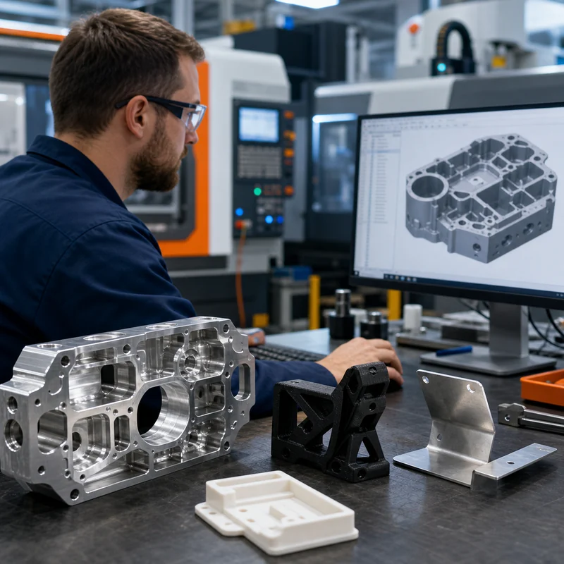
CNC machining removes material from a solid block, plate, rod, or extrusion. It is often the strongest choice when prototypes must use real production materials such as aluminum, stainless steel, brass, copper, titanium, ABS, Delrin, PEEK, or nylon. MTSPi commonly uses this route for precision parts, housings, brackets, shafts, fixtures, and functional prototypes.

  • Best for: functional prototypes, tight tolerances, threads, metal parts, engineering plastic parts, heat sinks, housings, and parts that will later be machined in production.
  • Advantages: real material properties, good surface finish, strong dimensional control, many finish options, and easy transition to low-volume production.
  • Limitations: internal sharp corners require radii, very complex hollow geometry may need design changes, and cost can rise with deep pockets or long machining time.

2. 3D Printing

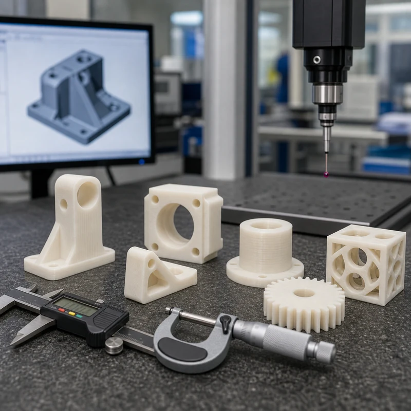
3D printing builds parts layer by layer. It is useful for quick design iteration, complex shapes, lightweight structures, internal channels, and early fit checks. Common options include FDM, SLA, SLS, MJF, and metal additive manufacturing. Each process has different accuracy, strength, surface finish, and material behavior.

Use 3D printing when geometry speed matters more than final material equivalence. For parts with critical mounting surfaces, threads, bearing fits, or sealing faces, printed prototypes may still need inserts, post-machining, or a later CNC version.

3. Sheet Metal Prototyping

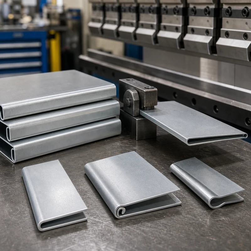
Sheet metal prototyping is ideal for covers, panels, chassis parts, brackets, shields, clips, and electrical enclosures. It can validate flat patterns, bends, hardware positions, PEM inserts, and assembly clearance. If the final product is sheet metal, a printed block model cannot fully replace a bent metal prototype.

  • Best for: brackets, enclosures, mounting plates, protective covers, and formed metal components.
  • Watch points: bend radius, grain direction, minimum flange length, hole-to-bend distance, and finish requirements.

4. Urethane Casting

Urethane casting uses silicone molds to produce small batches of plastic-like parts. It is useful for visual prototypes, sales samples, housings, colored parts, soft-touch components, and designs that need a molded appearance before injection tooling is ready. It is not the same as injection molding, but it can be a practical bridge for presentation and low-volume needs.

5. Prototype Injection Molding and Bridge Tooling

Prototype tooling is used when the team must test molded material, gate marks, shrinkage, living hinges, snap fits, or early production quantities. Tooling costs more than machining or printing, but it gives better information when the final part will be injection molded.

How to Choose the Right Rapid Prototyping Process

A practical process choice starts with the purpose of the prototype. Ask what decision the part must support. If the goal is visual approval, a fast printed or cast prototype may be enough. If the goal is mechanical testing, real material and accurate geometry matter more. If the goal is production planning, repeatability and inspection data become important.

Decision Factor Choose CNC Machining When Choose 3D Printing When Choose Tooling or Casting When
Material behavior The prototype must match aluminum, steel, brass, copper, titanium, or engineering plastic A substitute material is acceptable for early testing Molded plastic behavior or appearance is the main concern
Tolerance Holes, mating faces, threads, and flatness must be controlled Loose fit or visual geometry is acceptable Mold shrinkage and molded fits must be studied
Geometry Features can be accessed by cutting tools Complex internal geometry or organic forms are important Part is designed as a molded component
Quantity One piece to hundreds of parts One piece to small batches Dozens to thousands depending on tool strategy
Surface finish Machined, polished, anodized, plated, or bead blasted finish is required Layered or post-processed finish is acceptable Molded-like cosmetic finish is needed

CNC Machining vs 3D Printing for Rapid Prototypes

CNC machining and 3D printing are often compared because both can produce prototypes without full production tooling. The difference is how close the prototype needs to be to the final part. CNC machining is subtractive, so it starts with a real billet or sheet and produces a part with strong material behavior. 3D printing is additive, so it can produce complex shapes quickly, but layer direction and material substitutes may affect testing.

For example, a printed bracket may confirm shape and assembly clearance, but a machined aluminum CNC machining prototype is better for load testing, thread strength, heat transfer, and final finish review. A printed nylon duct may work for airflow validation, while Delrin CNC machining or nylon machining may be better for sliding wear or dimensional checks.

Cost Drivers in Rapid Prototyping

Prototype cost is controlled by geometry, material, tolerance, finish, quantity, and inspection. A simple part in common aluminum may be affordable by CNC machining. A part with deep pockets, thin walls, many setups, tight GD&T, and cosmetic anodizing will cost more. A printed part with large volume, expensive resin, support removal, and finishing can also become costly.

  • Reduce unnecessary tight tolerances on non-critical features.
  • Use standard material sizes when possible.
  • Avoid very deep narrow pockets unless they are functional.
  • Add radii that match practical cutting tools.
  • Separate cosmetic requirements from functional requirements on drawings.
  • Group similar prototypes to reduce setup and communication time.

Materials for Rapid Prototyping

Material selection should follow the prototype goal. For metal prototypes, aluminum is common because it machines quickly, has good strength-to-weight ratio, and accepts finishes such as anodizing. Stainless steel is chosen for corrosion resistance and strength. Brass and copper are chosen for electrical, thermal, or decorative requirements. Titanium is chosen when strength-to-weight and corrosion resistance matter. You can compare options in the CNC machining materials section.

For plastics, ABS is useful for general housings and prototypes, Delrin/POM is strong for low-friction precision parts, PEEK is used for demanding heat and chemical environments, and nylon is common for wear-resistant mechanical components. When the material is uncertain, the safest route is to explain the working environment and let the manufacturer compare options before quoting.

Surface Finishing for Prototype Parts

A prototype may need more than shape. Surface finish can affect appearance, corrosion resistance, wear, electrical behavior, and customer approval. Common options include bead blasting, anodizing, polishing, black oxide, powder coating, nickel plating, chrome plating, passivation, and painting. For finish selection, see MTSPi’s surface treatment guide.

Do not apply a finish only because it looks good on a sample. Finishing changes lead time, cost, dimensions, masking requirements, and sometimes material behavior. For precision prototypes, confirm whether inspection should happen before or after finishing.

From Prototype to Low-Volume Production

A good prototype should make production easier. If a design will later be CNC machined, use prototype feedback to simplify setups, remove unnecessary tight features, choose better stock size, and confirm inspection points. If a design will later be molded, use prototypes to refine wall thickness, ribs, bosses, draft, texture, and assembly features before tooling.

For small batches, rapid prototyping and custom CNC machining services can often bridge the gap between one-off samples and production tooling. This is useful when the design is still changing, the market is being tested, or annual demand does not justify hard tooling yet.

A Practical Selection Workflow

  • Define the prototype purpose: visual, fit, functional, regulatory, customer sample, or pilot batch.
  • List critical features: tolerances, threads, flatness, sealing faces, surface finish, and loaded areas.
  • Choose material based on the test, not only on availability.
  • Select a process that answers the key risk with the least wasted time.
  • Review DFM feedback before ordering, especially for thin walls, deep pockets, undercuts, and finishing.
  • Use inspection results and test feedback to revise the design before the next iteration.

When to Work With MTSPi

MTSPi is a good fit when your prototype needs real engineering material, controlled tolerances, practical DFM feedback, and a path toward repeatable low-volume supply. We can support CNC milled parts, turned parts, plastic prototypes, metal prototypes, surface finishing, and inspection planning for custom components.

To start a project, send your 3D model, 2D drawing, material preference, required quantity, finish, tolerance notes, and target application through the contact page. If you are still comparing processes, MTSPi can help decide whether CNC machining, 3D printing, sheet metal, or another prototyping route makes the most sense.

FAQ

What is the fastest rapid prototyping process?

For simple geometry and early concept checks, 3D printing is often fastest. For real metal or engineering plastic parts with precise dimensions, CNC machining may provide more useful results even if the lead time is slightly longer.

Is CNC machining good for rapid prototyping?

Yes. CNC machining is one of the best rapid prototyping methods when the part needs final-grade material, accurate holes, threads, flatness, surface finish, or functional testing close to production conditions.

What is the cheapest way to make a prototype?

The cheapest route depends on geometry and purpose. A simple printed model may be lowest cost for visual review, while a CNC machined part can be cheaper overall if it prevents failed tests, wrong material assumptions, or redesign later.

Can rapid prototypes be used as end-use parts?

Yes, especially when made by CNC machining or suitable sheet metal fabrication. Many low-volume end-use parts are produced through prototype-style workflows when tooling is not economical.

How do I send files for a rapid prototype quote?

Send a 3D CAD model, 2D drawing if tolerances matter, material choice, quantity, finish, and application notes. You can submit them through MTSPi’s contact page.
Categories
Blog CNC Materials

Rare Earth Metals: Properties, Uses, and Manufacturing Design Guide

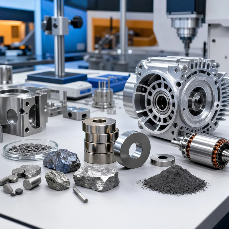
Rare earth metals are a family of 17 elements valued less for ordinary strength and more for magnetic, optical, electrical, catalytic, and high-temperature behavior. They are important in motors, sensors, displays, medical equipment, aerospace systems, renewable energy hardware, robotics, and precision electronics.

For manufacturing teams, rare earth metals are usually not selected like aluminum, steel, or titanium. They are most often used inside magnets, coatings, alloys, ceramics, polishing compounds, catalysts, and electronic materials. The surrounding housings, brackets, shafts, heat sinks, fixtures, and assembly parts still rely on conventional CNC materials. This guide explains the practical role of rare earth materials and how to think about them during custom CNC machining and product development.

What Are Rare Earth Metals?

Rare earth metals include the 15 lanthanide elements plus scandium and yttrium. The name can be confusing because many of these elements are not extremely scarce in the earth’s crust. They are called rare because they are commonly dispersed, mixed with other minerals, and difficult to separate into high-purity usable materials.

Group Elements
Lanthanides Lanthanum, cerium, praseodymium, neodymium, promethium, samarium, europium, gadolinium, terbium, dysprosium, holmium, erbium, thulium, ytterbium, lutetium
Related rare earth elements Scandium and yttrium

Why Rare Earth Metals Matter in Manufacturing

Rare earth materials solve problems that common structural metals cannot solve alone. Neodymium and dysprosium help create compact high-strength permanent magnets. Europium and terbium support display and lighting phosphors. Cerium is used in polishing and catalysts. Yttrium appears in ceramics, lasers, and high-performance materials. Scandium can improve certain aluminum alloys.

This does not mean rare earth metals replace structural metals. A motor may use rare earth magnets, but its housing may still be machined from aluminum. A sensor may depend on rare earth functional materials, while the enclosure may use stainless steel, brass, plastic, or titanium.

Common Rare Earth Metals and Uses

Element Symbol Manufacturing Relevance
Neodymium Nd Strong permanent magnets for motors, robotics, sensors, and compact assemblies
Dysprosium Dy Improves high-temperature magnet performance in demanding systems
Terbium Tb Phosphors, magnetostrictive materials, electronics, and specialty devices
Samarium Sm Samarium-cobalt magnets for high-temperature and harsh environments
Cerium Ce Polishing compounds, catalysts, glass additives, and alloy uses
Lanthanum La Batteries, optical glass, catalysts, and specialty alloys
Yttrium Y Ceramics, lasers, phosphors, thermal barrier materials, and electronics
Scandium Sc Aluminum alloy modification for lightweight high-performance components

Key Properties

Magnetic performance

The best-known rare earth application is permanent magnets. Neodymium-based magnets provide very high magnetic strength in a small package. Samarium-cobalt magnets are useful where heat resistance and corrosion behavior matter. These magnets appear in electric motors, actuators, speakers, sensors, holding fixtures, and compact motion-control systems.

Optical and luminescent behavior

Some rare earth elements emit specific colors or interact with light in useful ways. This makes them important in displays, LED lighting, lasers, fiber optics, medical imaging, inspection instruments, and optical glass.

Electrical and electronic function

Rare earth materials can influence magnetic fields, electronic behavior, and signal performance. They are not usually used as basic conductors like copper, but they help electronic systems achieve functions that standard metals cannot provide by themselves.

Temperature and stability advantages

Certain rare earth additions improve performance at elevated temperature. This is especially important for motors, aerospace hardware, energy systems, and industrial machinery where heat can reduce magnetic strength or dimensional stability.

Light Rare Earths vs Heavy Rare Earths

Rare earth elements are often grouped into light rare earth elements and heavy rare earth elements. Light rare earths generally have lower atomic numbers and are more abundant. Heavy rare earths are often less available and can be more strategically sensitive because they are important for high-performance magnets and specialized technologies.

Category Typical Elements Practical Note
Light rare earth elements Lanthanum, cerium, praseodymium, neodymium, samarium Often used in magnets, catalysts, glass, polishing, batteries, and alloys
Heavy rare earth elements Europium, gadolinium, terbium, dysprosium, yttrium, lutetium and related elements Important for high-temperature magnets, phosphors, lasers, ceramics, and advanced electronics

Rare Earth Metals vs Common CNC Metals

In CNC machining, material selection usually starts with strength, weight, corrosion resistance, machinability, thermal behavior, surface finish, and cost. Rare earth metals are different. They are selected for functional behavior inside a system rather than for ordinary load-bearing structure.

Material Family Main Role Typical CNC Relevance
Rare earth materials Magnetic, optical, catalytic, electronic, and high-temperature functions Usually used as magnets, additives, ceramics, coatings, or specialty components
Aluminum Lightweight structures, housings, heat sinks, brackets, prototypes Excellent machinability and weight reduction
Stainless steel Corrosion-resistant structural and mechanical parts Good for medical, food, marine, and industrial components
Titanium High strength-to-weight ratio and corrosion resistance Useful for aerospace, medical, and high-performance parts
Copper and brass Electrical, thermal, fittings, bushings, connectors Strong conductivity and good machinability depending on grade

Design Notes for Parts That Use Rare Earth Magnets

Many CNC machined parts interact with rare earth magnets even if the rare earth material itself is not machined as the main component. Examples include motor housings, sensor mounts, magnetic couplings, robotics grippers, test fixtures, encoder parts, and compact electromechanical assemblies.

  • Allow realistic pocket clearance for magnet installation and adhesive thickness.
  • Consider magnet orientation and assembly sequence before finalizing the housing design.
  • Protect brittle magnets from impact, edge loading, and press-fit stress.
  • Account for heat exposure because magnet strength can drop if the grade is not suitable.
  • Use coatings or encapsulation when corrosion or fluid exposure is possible.
  • Define inspection points for critical magnet seats, alignment features, and mating surfaces.

Material Selection for Advanced Assemblies

Rare earth materials often work best as part of a broader material system. A compact motor may combine rare earth magnets, copper windings, machined aluminum housing, stainless fasteners, and engineered plastic insulation. A sensor assembly may combine magnetic material with a machined bracket, sealed enclosure, and precision-located reference surfaces. MTSPi can review these surrounding CNC components through our materials library, surface treatment planning, and quality assurance workflow.

Quality and Inspection Considerations

For rare-earth-related assemblies, inspection should focus on the features that control fit, alignment, thermal path, and reliability. The machined part may need tight flatness, bore position, pocket depth, thread quality, or surface finish even when the functional rare earth element is purchased separately.

  • Check magnet pockets, bores, datum surfaces, and locating shoulders against the drawing.
  • Confirm surface finish where adhesives, seals, bearings, or magnetic components contact the part.
  • Plan coating thickness so plated or anodized surfaces do not close up critical fits.
  • Use documented inspection when the part supports motors, sensors, aerospace equipment, or medical devices.

How MTSPi Supports Manufacturing Projects

MTSPi does not treat rare earth metals as a generic substitute for normal CNC materials. Instead, we help engineers choose the right machined support parts around the functional material. Send the 3D model, 2D drawing, material preference, magnet or electronic component requirements, quantity, surface finish, and inspection expectations through our contact page. We can then review material options, machining strategy, tolerance risk, finishing, and assembly-critical features.

Related MTSPi Resources

FAQ

Are rare earth metals actually rare?

Not always. Many are reasonably abundant in the earth’s crust, but they are difficult to mine, separate, refine, and supply in high-purity forms.

Are rare earth metals stronger than steel?

No. Their main value is functional performance such as magnetism, optical behavior, and electronic properties. Steel, aluminum, titanium, and other engineering metals are usually better for structural CNC parts.

Which rare earth element is used in strong magnets?

Neodymium is widely used in strong permanent magnets. Dysprosium or terbium may be added for higher-temperature performance, while samarium-cobalt magnets are used in some harsh environments.

Can rare earth metals be CNC machined?

Some rare earth materials can be processed, but they are not common everyday CNC stock materials. In most projects, CNC machining is used for the surrounding housings, brackets, fixtures, and precision parts that hold or protect rare earth components.

What industries use rare earth materials?

Electric vehicles, robotics, aerospace, medical devices, renewable energy, electronics, sensors, lighting, displays, and industrial automation all use rare earth materials in different ways.

Categories
Blog CNC Machining Basics

What Is NC Machining? Process, Types, and CNC Comparison

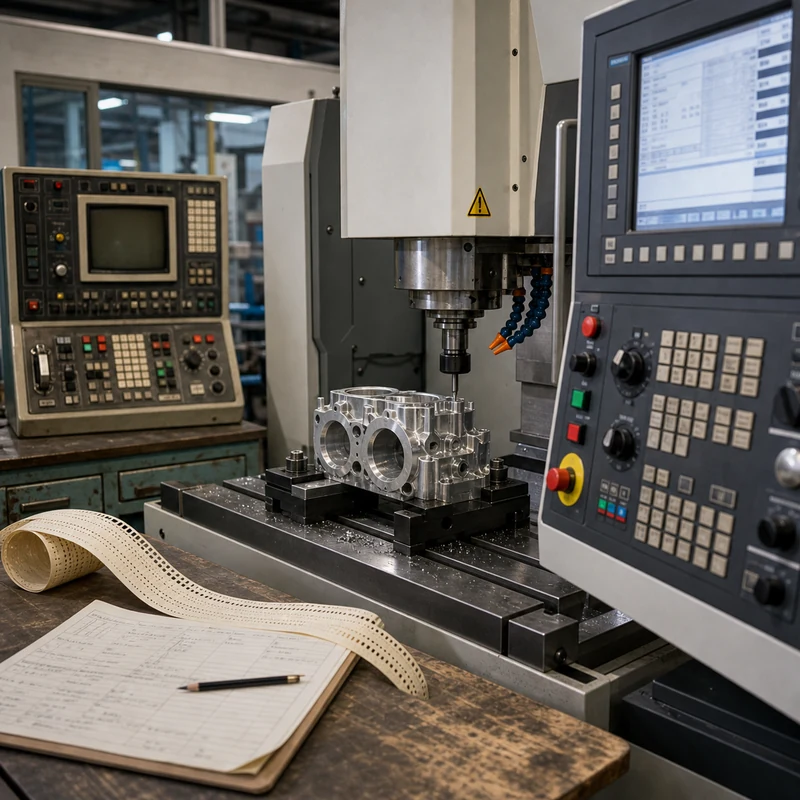
NC machining, or numerical control machining, is the earlier form of automated machine control that uses coded instructions to move machine tools. It created the foundation for modern CNC machining.

The key difference is that CNC uses computer-based control, easier program editing, feedback, simulation, and more flexible automation. NC is historically important, but CNC dominates modern precision manufacturing.

Quick Guide to Nc Machining

Item Purpose Manufacturing Note
NC machining Older automated machine tools Less flexible and harder to edit
CNC machining Modern milling, turning, drilling, routing Computer-controlled and highly repeatable
Manual machining One-off adjustments and simple work Operator skill drives consistency
CAM workflow Programming complex parts Generates efficient toolpaths for CNC

Process Selection Notes

The best process depends on material, geometry, tolerance, quantity, surface finish, heat effects, burr requirements, and whether the part needs secondary machining or finishing.

  • Match the process to the material and geometry.
  • Confirm critical dimensions before quoting.
  • Plan finishing and inspection before production.
  • Use prototypes to validate fit when the assembly risk is high.

Common Applications

Nc Machining is relevant for prototypes, custom components, fixtures, low-volume manufacturing, maintenance parts, and engineering projects where function, cost, and lead time must be balanced.

Cost Factors

Cost usually depends on setup time, material price, number of operations, tool access, tolerance requirements, surface finish, inspection depth, and batch quantity.

Design and Sourcing Notes

The safest design approach is to define the part’s function first, then assign tolerances only where they affect assembly, movement, sealing, safety, or long-term performance.

  • Avoid unnecessary tight tolerances on non-critical surfaces.
  • Keep internal corners, hole depths, wall thickness, and tool access realistic.
  • Call out cosmetic surfaces separately from functional surfaces.
  • Include material, finish, quantity, and inspection notes in the RFQ package.

Quality Checks That Matter

Quality control may include visual inspection, dimensional measurement, thread checks, gauge checks, flatness checks, runout checks, surface finish checks, or CMM inspection depending on the part’s risk and function.

Related MTSPi Resources

FAQ

What is the main consideration for NC machining?

The main consideration is whether the design, material, and process can meet the functional requirements without adding unnecessary cost or risk.

Can MTSPi help with custom parts for this topic?

Yes. MTSPi can review drawings, material requirements, tolerances, finishing, and inspection needs for custom CNC machined or related manufacturing parts.

What should I send for a quote?

Send 3D CAD, 2D drawings, material grade, quantity, surface finish requirements, tolerance notes, and any critical assembly information.

Categories
Blog Quality & Tolerances

How Accurate Are 3D Printed Parts? Tolerances, Materials, and Inspection

3D printed parts can be accurate enough for prototypes, fixtures, and some end-use applications, but accuracy depends on process, material, geometry, orientation, wall thickness, shrinkage, and post-processing.

The most important question is not whether 3D printing is accurate in general, but whether a specific process can hold the dimensions that matter for the part’s function.

Quick Guide to 3D Printed Parts Dimensional Accuracy

Item Purpose Manufacturing Note
FDM Concept models, fixtures, large prototypes Layer lines and anisotropy affect accuracy
SLA Detailed visual prototypes Good detail but resin behavior matters
SLS/MJF Functional nylon parts Good for complex shapes and batches
Metal printing Complex metal parts Often needs machining for critical surfaces

Process Selection Notes

The best process depends on material, geometry, tolerance, quantity, surface finish, heat effects, burr requirements, and whether the part needs secondary machining or finishing.

  • Match the process to the material and geometry.
  • Confirm critical dimensions before quoting.
  • Plan finishing and inspection before production.
  • Use prototypes to validate fit when the assembly risk is high.

Common Applications

3D Printed Parts Dimensional Accuracy is relevant for prototypes, custom components, fixtures, low-volume manufacturing, maintenance parts, and engineering projects where function, cost, and lead time must be balanced.

Cost Factors

Cost usually depends on setup time, material price, number of operations, tool access, tolerance requirements, surface finish, inspection depth, and batch quantity.

Design and Sourcing Notes

The safest design approach is to define the part’s function first, then assign tolerances only where they affect assembly, movement, sealing, safety, or long-term performance.

  • Avoid unnecessary tight tolerances on non-critical surfaces.
  • Keep internal corners, hole depths, wall thickness, and tool access realistic.
  • Call out cosmetic surfaces separately from functional surfaces.
  • Include material, finish, quantity, and inspection notes in the RFQ package.

Quality Checks That Matter

Quality control may include visual inspection, dimensional measurement, thread checks, gauge checks, flatness checks, runout checks, surface finish checks, or CMM inspection depending on the part’s risk and function.

Related MTSPi Resources

FAQ

What is the main consideration for 3D printed parts dimensional accuracy?

The main consideration is whether the design, material, and process can meet the functional requirements without adding unnecessary cost or risk.

Can MTSPi help with custom parts for this topic?

Yes. MTSPi can review drawings, material requirements, tolerances, finishing, and inspection needs for custom CNC machined or related manufacturing parts.

What should I send for a quote?

Send 3D CAD, 2D drawings, material grade, quantity, surface finish requirements, tolerance notes, and any critical assembly information.

Categories
Blog CNC Materials

Brass Grades for CNC Machining: Selection Guide for Custom Parts

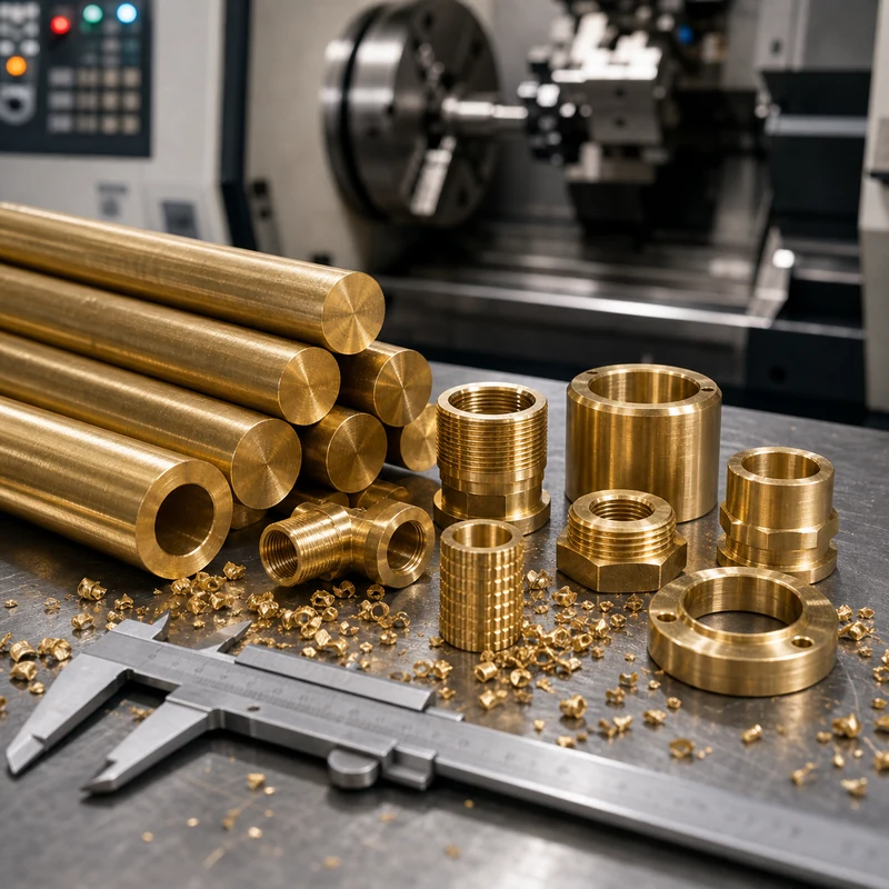
Brass is a copper-zinc alloy family known for excellent machinability, attractive appearance, corrosion resistance, and good electrical performance. Different brass grades behave differently during cutting, threading, forming, and finishing.

For CNC parts, brass is often selected for fittings, bushings, inserts, connectors, valves, decorative hardware, and electrical components.

Quick Guide to Brass Grades For Cnc Machining

Item Purpose Manufacturing Note
C360 Free-cutting brass Excellent machinability for turned parts
C260 Cartridge brass Good formability and corrosion resistance
C464 Naval brass Better marine corrosion resistance
Lead-free brass Applications with regulatory or environmental requirements Machinability varies by alloy

Material Selection Notes

Material choice affects machinability, tool wear, achievable tolerance, corrosion resistance, surface finish, and long-term part performance. Always connect material grade to the real application.

  • Match the process to the material and geometry.
  • Confirm critical dimensions before quoting.
  • Plan finishing and inspection before production.
  • Use prototypes to validate fit when the assembly risk is high.

Common Applications

Brass Grades For Cnc Machining is relevant for prototypes, custom components, fixtures, low-volume manufacturing, maintenance parts, and engineering projects where function, cost, and lead time must be balanced.

Cost Factors

Cost usually depends on setup time, material price, number of operations, tool access, tolerance requirements, surface finish, inspection depth, and batch quantity.

Design and Sourcing Notes

The safest design approach is to define the part’s function first, then assign tolerances only where they affect assembly, movement, sealing, safety, or long-term performance.

  • Avoid unnecessary tight tolerances on non-critical surfaces.
  • Keep internal corners, hole depths, wall thickness, and tool access realistic.
  • Call out cosmetic surfaces separately from functional surfaces.
  • Include material, finish, quantity, and inspection notes in the RFQ package.

Quality Checks That Matter

Quality control may include visual inspection, dimensional measurement, thread checks, gauge checks, flatness checks, runout checks, surface finish checks, or CMM inspection depending on the part’s risk and function.

Related MTSPi Resources

FAQ

What is the main consideration for brass grades for CNC machining?

The main consideration is whether the design, material, and process can meet the functional requirements without adding unnecessary cost or risk.

Can MTSPi help with custom parts for this topic?

Yes. MTSPi can review drawings, material requirements, tolerances, finishing, and inspection needs for custom CNC machined or related manufacturing parts.

What should I send for a quote?

Send 3D CAD, 2D drawings, material grade, quantity, surface finish requirements, tolerance notes, and any critical assembly information.

Categories
Blog Manufacturing Process Comparisons

CNC Router vs Laser Cutting: Differences, Materials, Accuracy, and Cost

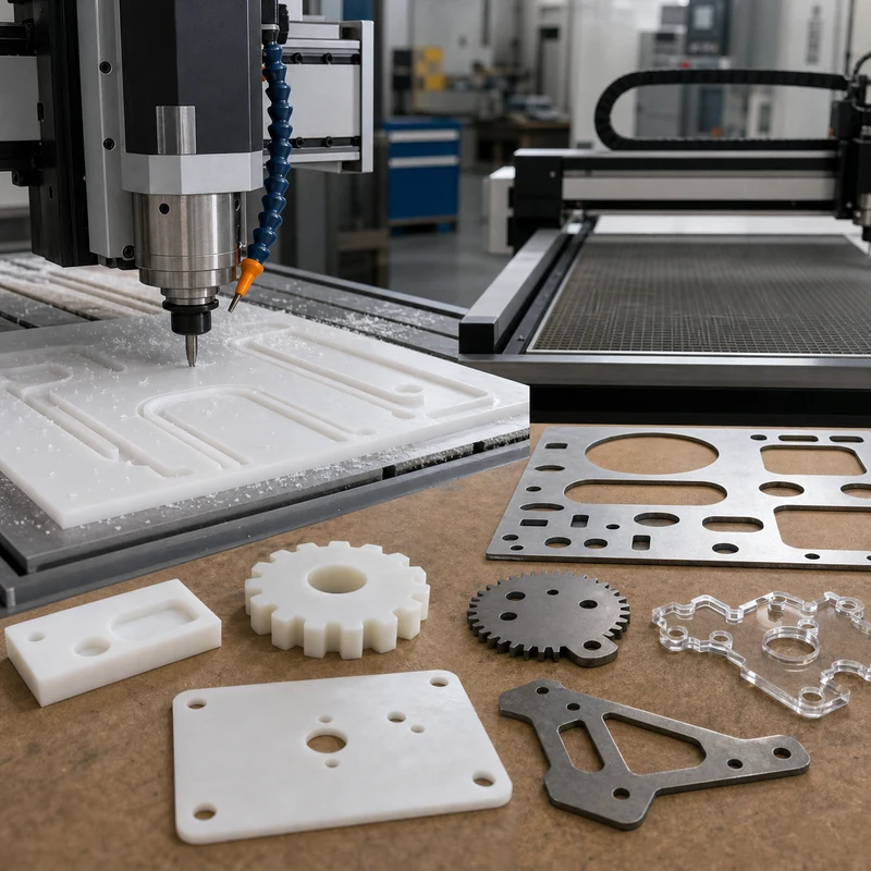
CNC routers and laser cutters both follow digital toolpaths, but they remove or separate material in very different ways. A router uses a rotating cutting tool; a laser uses focused heat.

Choosing between them depends on material, thickness, edge quality, tolerance, kerf, heat-affected zone, and whether the part needs pockets, countersinks, engraving, or clean cut profiles.

Quick Guide to Cnc Router Vs Laser Cutting

Item Purpose Manufacturing Note
CNC router Plastics, wood, composites, aluminum sheet, foam Can cut pockets and 3D features
Laser cutting Sheet metal, acrylic, thin profiles Fast profile cutting with narrow kerf
Router limitation Tool radius and cutting force Internal corners need radii
Laser limitation Heat-affected edge Some materials discolor, melt, or harden

Process Selection Notes

The best process depends on material, geometry, tolerance, quantity, surface finish, heat effects, burr requirements, and whether the part needs secondary machining or finishing.

  • Match the process to the material and geometry.
  • Confirm critical dimensions before quoting.
  • Plan finishing and inspection before production.
  • Use prototypes to validate fit when the assembly risk is high.

Common Applications

Cnc Router Vs Laser Cutting is relevant for prototypes, custom components, fixtures, low-volume manufacturing, maintenance parts, and engineering projects where function, cost, and lead time must be balanced.

Cost Factors

Cost usually depends on setup time, material price, number of operations, tool access, tolerance requirements, surface finish, inspection depth, and batch quantity.

Design and Sourcing Notes

The safest design approach is to define the part’s function first, then assign tolerances only where they affect assembly, movement, sealing, safety, or long-term performance.

  • Avoid unnecessary tight tolerances on non-critical surfaces.
  • Keep internal corners, hole depths, wall thickness, and tool access realistic.
  • Call out cosmetic surfaces separately from functional surfaces.
  • Include material, finish, quantity, and inspection notes in the RFQ package.

Quality Checks That Matter

Quality control may include visual inspection, dimensional measurement, thread checks, gauge checks, flatness checks, runout checks, surface finish checks, or CMM inspection depending on the part’s risk and function.

Related MTSPi Resources

FAQ

What is the main consideration for CNC router vs laser cutting?

The main consideration is whether the design, material, and process can meet the functional requirements without adding unnecessary cost or risk.

Can MTSPi help with custom parts for this topic?

Yes. MTSPi can review drawings, material requirements, tolerances, finishing, and inspection needs for custom CNC machined or related manufacturing parts.

What should I send for a quote?

Send 3D CAD, 2D drawings, material grade, quantity, surface finish requirements, tolerance notes, and any critical assembly information.

Categories
Blog Industries & Applications

Car Chassis Guide: Types, Functions, Components, and Manufacturing Notes

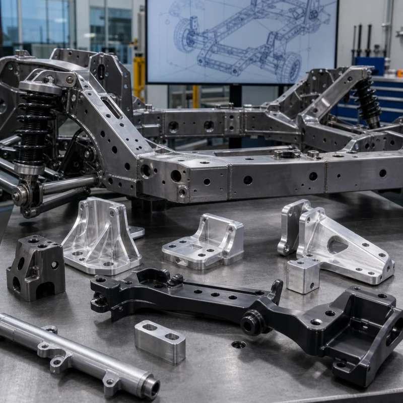
A car chassis is the structural foundation that supports the body, drivetrain, suspension, steering, and safety systems. It must manage load, vibration, impact, and alignment across the entire vehicle.

Chassis-related parts require strong materials, accurate mounting points, consistent welding or fastening, and reliable corrosion protection.

Quick Guide to Car Chassis

Item Purpose Manufacturing Note
Ladder frame Trucks and heavy-duty platforms Strong and simple, but heavier
Monocoque Modern passenger vehicles Efficient packaging and lower weight
Space frame Performance and specialty vehicles High stiffness with engineered tubes or castings
Subframe Supports suspension or drivetrain modules Mounting hole accuracy is essential

Automotive Manufacturing Notes

Automotive components must balance load, vibration, material strength, corrosion resistance, assembly fit, and production repeatability. CNC machining is often used for brackets, housings, shafts, spacers, connectors, prototypes, and low-volume performance components.

  • Match the process to the material and geometry.
  • Confirm critical dimensions before quoting.
  • Plan finishing and inspection before production.
  • Use prototypes to validate fit when the assembly risk is high.

Common Applications

Car Chassis is relevant for prototypes, custom components, fixtures, low-volume manufacturing, maintenance parts, and engineering projects where function, cost, and lead time must be balanced.

Cost Factors

Cost usually depends on setup time, material price, number of operations, tool access, tolerance requirements, surface finish, inspection depth, and batch quantity.

Design and Sourcing Notes

The safest design approach is to define the part’s function first, then assign tolerances only where they affect assembly, movement, sealing, safety, or long-term performance.

  • Avoid unnecessary tight tolerances on non-critical surfaces.
  • Keep internal corners, hole depths, wall thickness, and tool access realistic.
  • Call out cosmetic surfaces separately from functional surfaces.
  • Include material, finish, quantity, and inspection notes in the RFQ package.

Quality Checks That Matter

Quality control may include visual inspection, dimensional measurement, thread checks, gauge checks, flatness checks, runout checks, surface finish checks, or CMM inspection depending on the part’s risk and function.

Related MTSPi Resources

FAQ

What is the main consideration for car chassis?

The main consideration is whether the design, material, and process can meet the functional requirements without adding unnecessary cost or risk.

Can MTSPi help with custom parts for this topic?

Yes. MTSPi can review drawings, material requirements, tolerances, finishing, and inspection needs for custom CNC machined or related manufacturing parts.

What should I send for a quote?

Send 3D CAD, 2D drawings, material grade, quantity, surface finish requirements, tolerance notes, and any critical assembly information.

Categories
Blog CNC Machining Basics

Sheet Metal Hemming: Process, Types, Advantages, and Design Rules

Sheet metal hemming folds an edge back onto itself to create a safer, stronger, and cleaner border. It is common in panels, covers, doors, automotive parts, enclosures, and consumer products.

A hem can remove sharp edges, improve stiffness, hide a raw cut edge, and help two sheets join together. The process must be planned with bend radius, material thickness, grain direction, and tooling clearance in mind.

Quick Guide to Sheet Metal Hemming

Item Purpose Manufacturing Note
Open hem Edge is folded but leaves a small gap Useful when material may crack if flattened
Closed hem Edge is folded flat Clean appearance but higher forming stress
Teardrop hem Rounded internal gap Good for harder or thicker materials
Rope hem Rolled circular edge Adds stiffness and safer handling

Process Selection Notes

The best process depends on material, geometry, tolerance, quantity, surface finish, heat effects, burr requirements, and whether the part needs secondary machining or finishing.

  • Match the process to the material and geometry.
  • Confirm critical dimensions before quoting.
  • Plan finishing and inspection before production.
  • Use prototypes to validate fit when the assembly risk is high.

Common Applications

Sheet Metal Hemming is relevant for prototypes, custom components, fixtures, low-volume manufacturing, maintenance parts, and engineering projects where function, cost, and lead time must be balanced.

Cost Factors

Cost usually depends on setup time, material price, number of operations, tool access, tolerance requirements, surface finish, inspection depth, and batch quantity.

Design and Sourcing Notes

The safest design approach is to define the part’s function first, then assign tolerances only where they affect assembly, movement, sealing, safety, or long-term performance.

  • Avoid unnecessary tight tolerances on non-critical surfaces.
  • Keep internal corners, hole depths, wall thickness, and tool access realistic.
  • Call out cosmetic surfaces separately from functional surfaces.
  • Include material, finish, quantity, and inspection notes in the RFQ package.

Quality Checks That Matter

Quality control may include visual inspection, dimensional measurement, thread checks, gauge checks, flatness checks, runout checks, surface finish checks, or CMM inspection depending on the part’s risk and function.

Related MTSPi Resources

FAQ

What is the main consideration for sheet metal hemming?

The main consideration is whether the design, material, and process can meet the functional requirements without adding unnecessary cost or risk.

Can MTSPi help with custom parts for this topic?

Yes. MTSPi can review drawings, material requirements, tolerances, finishing, and inspection needs for custom CNC machined or related manufacturing parts.

What should I send for a quote?

Send 3D CAD, 2D drawings, material grade, quantity, surface finish requirements, tolerance notes, and any critical assembly information.

Categories
Blog Industries & Applications

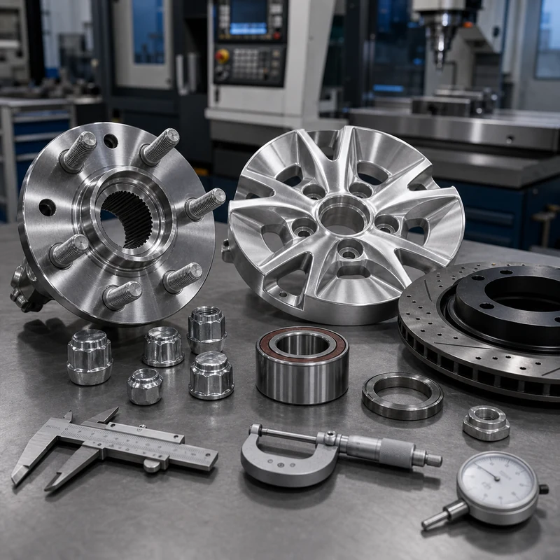
Car Wheel Parts Explained: Components, Materials, and CNC Manufacturing Notes

Quick answer: Car wheel systems include the rim, hub, spokes, center bore, lug holes, valve stem, wheel fasteners, hub-centric features, and related brake or suspension interfaces. Many wheel-related components require accurate machining for fit, balance, strength, and safety.

Car Wheel Parts and Manufacturing Notes

Wheel parts are often discussed as simple automotive components, but their interfaces are precision-sensitive. Center bores, bolt patterns, mounting faces, and hub surfaces must be controlled so the assembly fits correctly and runs smoothly.

Key Points for Buyers and Engineers

Topic What to know Practical impact
Center bore Locates the wheel on the hub Affects fit and vibration.
Bolt pattern Defines lug hole location and count Controls assembly compatibility.
Mounting face Contacts the hub or spacer Flatness and cleanliness matter.
Spacers and adapters Modify offset or fitment Need accurate turning and milling.

How This Affects CNC Machined Parts

CNC machining is often used for prototypes, adapters, spacers, test fixtures, and related automotive components. For round wheel-related parts, review CNC turning; for brackets and adapters, review CNC milling.

Design and Purchasing Checklist

  • Confirm bolt circle, center bore, thickness, and material.
  • Define flatness for mounting faces.
  • Avoid sharp corners where stress matters.
  • Specify finish and corrosion protection.
  • Inspect critical dimensions before assembly testing.

Related MTSPi Resources

FAQ

Are car wheel parts CNC machined?

Some wheel-related components, prototypes, adapters, fixtures, and precision interfaces are CNC machined.

Why does center bore accuracy matter?

It helps locate the wheel on the hub and can affect fit, vibration, and assembly quality.

What material is used for wheel adapters?

Aluminum alloys and steels are common, depending on load, design, and application.

Need help with automotive CNC part review?

Send drawings, material, quantity, finish, tolerance notes, and application requirements. MTSPi can review manufacturability before quoting.

Contact MTSPi for engineering and quote support

Practical Buyer Notes

Automotive component pages need more specific engineering detail than a simple parts list. For wheel-related parts, fit, balance, concentricity, flatness, corrosion protection, and material strength all matter.

This page can target informational searches while still connecting to CNC machining by explaining wheel spacers, adapters, hubs, test fixtures, brake-related interfaces, and prototype components.

How to Evaluate This Topic on a Real Drawing

Decision point Recommended approach Why it matters
Center bore Control diameter and concentricity Affects hub fit and vibration
Bolt pattern Verify PCD and hole size Controls assembly compatibility
Mounting face Control flatness and burrs Improves contact and safety
Material and finish Use suitable aluminum or steel plus corrosion protection Supports strength and durability

Common Mistakes to Avoid

  • Ignoring hub-centric fit when wheel alignment matters.
  • Leaving bolt pattern or chamfer details unclear.
  • Using cosmetic finish without corrosion or wear planning.
  • Treating automotive prototype parts as if inspection is optional.

Recommended MTSPi Review Workflow

MTSPi should review automotive parts by interface. Any feature that touches a hub, fastener, brake component, or mating assembly should be treated as critical.

  1. Confirm the part function, operating environment, and assembly risk.
  2. Review material, process, tolerance, surface finish, and inspection requirements together.
  3. Separate critical features from general dimensions so cost is not wasted on non-functional details.
  4. Use related resources such as CNC materials, surface treatment, and quality assurance to complete the specification.
  5. Send the final drawing package to MTSPi for quote review before production.

What to Send for a Faster Quote

Send drawings with center bore, bolt circle, thickness, offset-related dimensions, material grade, finish, and inspection needs clearly marked.

  • 3D CAD file and 2D drawing with revision number.
  • Material grade or acceptable alternatives.
  • Quantity, delivery target, and whether samples are required first.
  • Critical dimensions, thread callouts, finish notes, and inspection requirements.
  • Application notes when the part is used in heat, moisture, wear, vibration, or visible assemblies.

Deeper Engineering Notes

For car wheel parts, the strongest page is not just a definition. It should help a buyer decide what information belongs on the drawing, what questions to ask a supplier, and which details affect cost, quality, and delivery. In real RFQ work, the important details are usually hub-centric fit, bolt circle accuracy, mounting face flatness, spacer thickness, coating, and load path. These details decide whether the supplier can quote confidently or has to return with repeated questions.

The common risk is treating wheel-related interfaces as cosmetic dimensions instead of safety-related functional features. That risk can make the content look complete on the surface but weak in a real manufacturing situation. A stronger specification connects the topic to material behavior, machine access, tolerance control, finishing, and inspection before the order is released.

Example Specification Review

Review area Question to answer Good specification practice
Function What does this feature or part need to do? Describe the load, fit, motion, appearance, sealing, or assembly requirement.
Material Is the selected material suitable for the environment? Confirm strength, heat, corrosion, wear, chemical exposure, and cosmetic needs.
Geometry Can the feature be reached by standard tools? Review depth, corner radius, wall thickness, tool clearance, and setup direction.
Tolerance Which dimensions are truly critical? Use tight tolerances only where function requires them and keep general dimensions practical.
Verification How will acceptance be checked? Define gauges, CMM checks, roughness measurement, thread inspection, or visual standards when needed.

How This Page Should Support Ranking

This topic can attract both beginner searches and buyer searches. The beginner wants a clear answer; the buyer wants enough detail to make a manufacturing decision. A page has a better chance to rank when it answers the simple question first, then adds examples, process limits, design notes, comparison tables, and practical next steps.

That is also why internal links should be helpful rather than forced. A reader should naturally move from this page to a process page, material page, surface finish page, inspection page, or quote page only when that next step solves a real question.

Conclusion

Car wheel components need more than a rough shape. Fit, balance, material, finish, and inspection are important when CNC machining wheel-related parts.

Categories
Blog Industries & Applications

Car Steering Components: System Parts, Function, and Manufacturing Notes

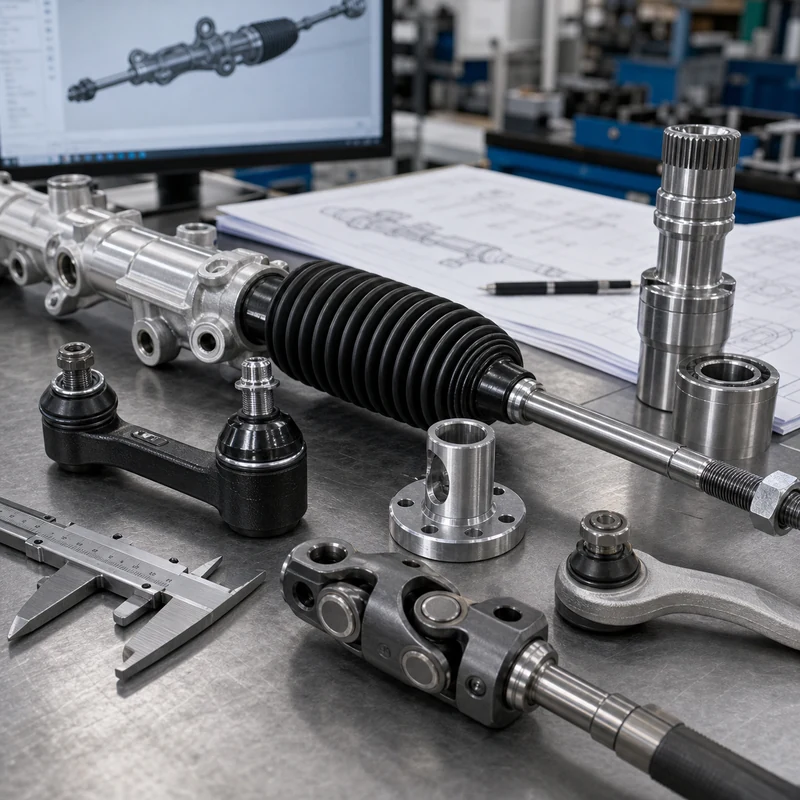
Steering components convert driver input into controlled wheel movement. A reliable steering system depends on links, joints, racks, shafts, housings, bearings, and brackets that keep motion smooth and predictable.

Steering racks, tie rods, universal joints, brackets, and housings need accurate machining because looseness, poor alignment, or weak material can affect vehicle response.

Quick Guide to Car Steering Components

Item Purpose Manufacturing Note
Steering shaft Transfers rotation from wheel to rack or box Concentricity and joint fit matter
Tie rod Connects steering rack to wheel knuckle Threads, ball joint seats, and corrosion protection matter
Rack housing Supports internal rack and pinion Bores and mounting surfaces need accuracy
Brackets Mount steering parts to chassis Strength and hole position are critical

Automotive Manufacturing Notes

Automotive components must balance load, vibration, material strength, corrosion resistance, assembly fit, and production repeatability. CNC machining is often used for brackets, housings, shafts, spacers, connectors, prototypes, and low-volume performance components.

  • Match the process to the material and geometry.
  • Confirm critical dimensions before quoting.
  • Plan finishing and inspection before production.
  • Use prototypes to validate fit when the assembly risk is high.

Common Applications

Car Steering Components is relevant for prototypes, custom components, fixtures, low-volume manufacturing, maintenance parts, and engineering projects where function, cost, and lead time must be balanced.

Cost Factors

Cost usually depends on setup time, material price, number of operations, tool access, tolerance requirements, surface finish, inspection depth, and batch quantity.

Design and Sourcing Notes

The safest design approach is to define the part’s function first, then assign tolerances only where they affect assembly, movement, sealing, safety, or long-term performance.

  • Avoid unnecessary tight tolerances on non-critical surfaces.
  • Keep internal corners, hole depths, wall thickness, and tool access realistic.
  • Call out cosmetic surfaces separately from functional surfaces.
  • Include material, finish, quantity, and inspection notes in the RFQ package.

Quality Checks That Matter

Quality control may include visual inspection, dimensional measurement, thread checks, gauge checks, flatness checks, runout checks, surface finish checks, or CMM inspection depending on the part’s risk and function.

Related MTSPi Resources

FAQ

What is the main consideration for car steering components?

The main consideration is whether the design, material, and process can meet the functional requirements without adding unnecessary cost or risk.

Can MTSPi help with custom parts for this topic?

Yes. MTSPi can review drawings, material requirements, tolerances, finishing, and inspection needs for custom CNC machined or related manufacturing parts.

What should I send for a quote?

Send 3D CAD, 2D drawings, material grade, quantity, surface finish requirements, tolerance notes, and any critical assembly information.

Request A Quote

We'll Send You Back with Price Immediately!

DEC 1-31

XMAS SPECEIL

Up to

40% off

Car Steering Components: System Parts, Function, and Manufacturing Notes

We'll Send You Back with Price Immediately!