Categories
Blog Quality & Tolerances

What Is CMM Inspection? Complete Guide to Coordinate Measuring Machines for CNC Parts

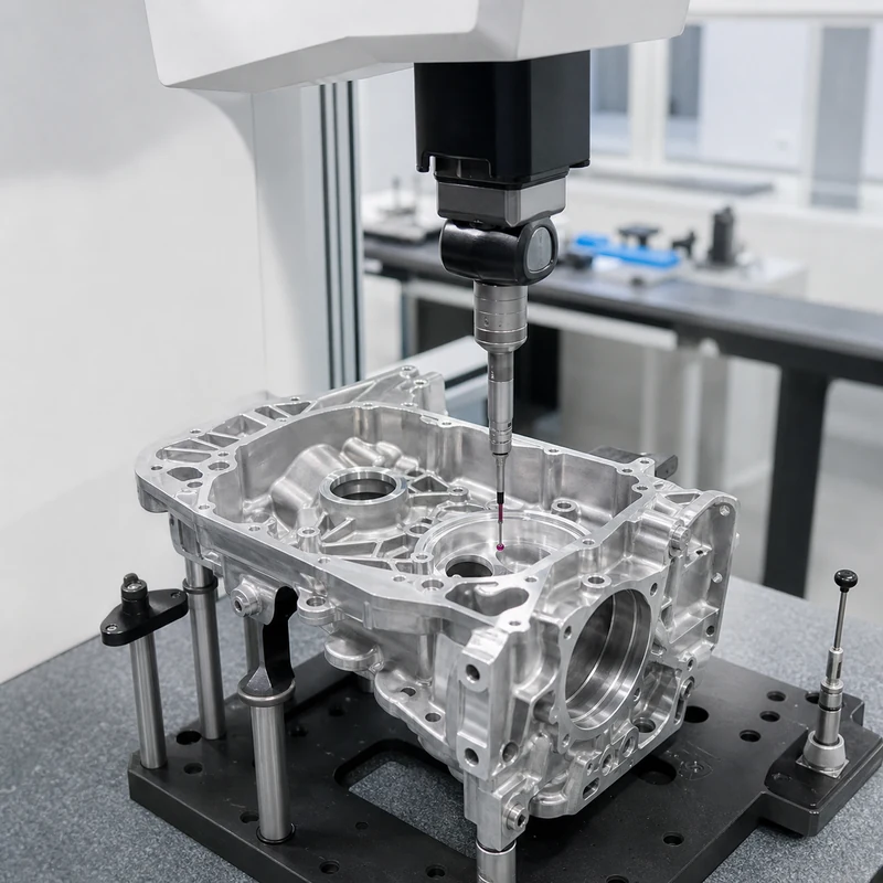
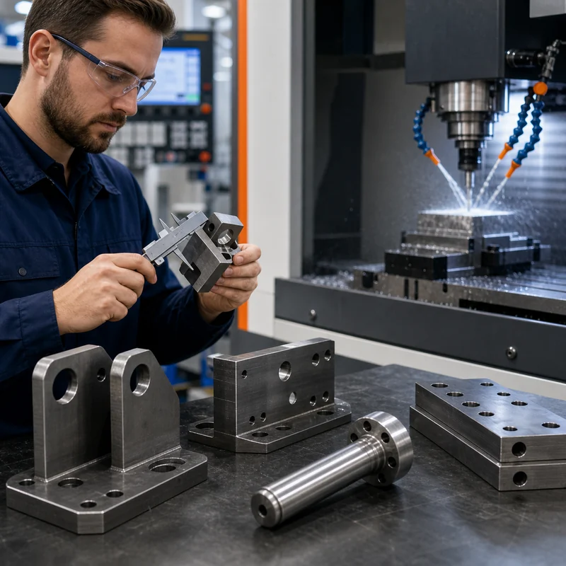
Quick answer: CMM inspection uses a coordinate measuring machine to measure part features in three-dimensional space. It checks dimensions, hole positions, profiles, flatness, perpendicularity, true position, datums, and GD&T requirements. For CNC machined parts, CMM inspection is most useful when features are tight, complex, datum-based, or critical to assembly.

What Is a CMM?

A CMM, or coordinate measuring machine, is an inspection system that measures points on a part using a probe or sensor. The machine records X, Y, and Z coordinates and compares them with the drawing or CAD model. This allows inspectors to verify whether a machined part is within tolerance.

CMM inspection is common for precision CNC parts because many features cannot be judged reliably with calipers alone. Hole patterns, datum relationships, true position, perpendicularity, flatness, and complex profiles need a measurement method that understands the part in 3D space.

What CMM Inspection Can Measure

Feature What CMM checks Why it matters
Hole position Location relative to datums or other holes Controls assembly alignment
Flatness Variation across a surface Important for sealing, mounting, and contact faces
Perpendicularity Angle relationship between axes or surfaces Important for housings, brackets, and fixtures
Profile Deviation from CAD surface or drawing profile Useful for complex milled geometry
True position GD&T-controlled feature location Common for precision hole patterns
Distance and size Lengths, widths, diameters, depths Confirms basic drawing dimensions

How CMM Inspection Works

First, the inspector reviews the drawing and identifies datums, critical features, tolerance zones, and measurement requirements. The part is cleaned and fixtured so it sits in a repeatable position. The CMM then touches or scans selected points. Software compares the measured data with the nominal CAD or drawing values and creates a report.

For repeat production, a CMM program can be saved and reused. This helps measure the same features consistently across batches. For first article inspection, the report may include a broader set of dimensions to validate the initial production process.

CMM Inspection vs Manual Inspection

Inspection method Best for Limitations
Calipers Quick checks of general dimensions Limited for complex geometry and high precision
Micrometers Accurate outside diameters and thickness Feature access and operator method matter
Pin / plug gauges Hole size and fit checks Does not fully describe position or geometry
Thread gauges Internal or external thread fit Does not measure all thread geometry
CMM Datum-based geometry, GD&T, complex parts More time and cost than simple manual checks

When Should Buyers Request CMM Inspection?

  • The part has tight tolerance hole patterns.
  • The drawing uses GD&T such as true position, profile, flatness, or perpendicularity.
  • The part must fit into a larger assembly with little adjustment.
  • The part has multiple machined sides or complex surfaces.
  • The order requires first article inspection or documented quality records.
  • The cost of failure is higher than the cost of measurement.

What Should a CMM Report Include?

A useful CMM report should include part name, drawing number, revision, inspection date, measured features, nominal values, tolerance limits, actual measurements, deviation, pass/fail result, datum reference, and inspector notes. For regulated or high-value projects, material certificate, finish confirmation, and first article documentation may also be needed.

GD&T, Datums, and CMM Inspection

GD&T gives more precise control over how features relate to each other. A hole may pass a simple diameter check but still fail true position if it is not located correctly from the datums. CMM inspection is strong in this situation because it can evaluate the feature within a coordinate system based on the drawing’s datum structure.

If the datum structure is unclear, inspection becomes uncertain. Buyers should make sure the drawing identifies primary, secondary, and tertiary datums where needed. For CNC suppliers, clear datums also help plan workholding and machining sequence.

CMM Inspection for CNC Milling and Turning

For CNC milled parts, CMM inspection is useful for hole patterns, pockets, flatness, profiles, and multi-side relationships. For CNC turned parts, it can support checks for bores, faces, grooves, concentric relationships, cross holes, and secondary milled features. It works best when the drawing clearly separates critical and non-critical dimensions.

How to Reduce Inspection Cost Without Increasing Risk

  • Identify critical dimensions instead of requiring a full report for every feature.
  • Use general tolerance notes for non-critical dimensions.
  • Provide CAD and drawing files together.
  • Define datum structure clearly.
  • Use gauges for simple features and CMM for features that need 3D relationships.
  • Agree on sampling quantity before production.

FAQ

Is CMM inspection required for every CNC part?

No. Many simple parts can be checked with calipers, micrometers, gauges, or visual inspection. CMM is most valuable for precision, complex, or GD&T-controlled parts.

Can CMM inspect threads?

CMM can check thread location and related geometry, but thread fit is usually checked with go/no-go thread gauges.

What is the difference between CMM and FAI?

CMM is a measurement method. First article inspection is a broader process that may include CMM measurements, material checks, finish checks, and documentation.

Does CMM inspection add lead time?

Yes, it can add inspection time, especially for complex reports. But it can reduce risk when parts are expensive or assembly-critical.

What files help CMM inspection?

A 2D drawing with tolerances and datums is essential. A 3D CAD model can help with programming and profile comparison.

Need inspection support for precision parts?

Send your drawing, GD&T notes, CAD file, and critical dimensions. MTSPi can review the right inspection method before quoting.

Contact MTSPi for CNC inspection support

Conclusion

CMM inspection helps confirm that CNC machined parts match the drawing in three-dimensional space. It is most useful for complex geometry, datum-based tolerances, first article inspection, and parts where assembly risk is high.

Categories
Blog Design, Cost & Sourcing Machine Tools & Programming

How CNC Machining Software Improves Production Efficiency

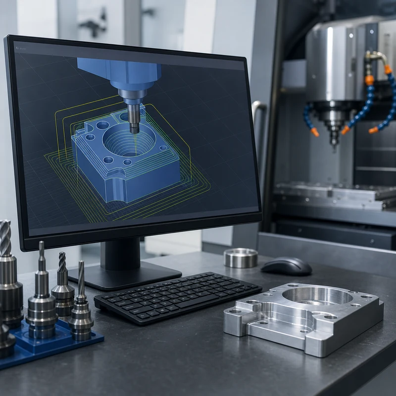
CNC machining software improves production efficiency by turning a CAD model into controlled toolpaths, repeatable setup instructions, reliable simulations, and measurable process data. Good software does not replace skilled machinists, but it gives programmers and production teams better ways to reduce waste, avoid collisions, shorten setup time, and standardize repeat jobs.

For custom parts, the software workflow matters as much as the machine itself. MTSPi uses digital review, programming, process planning, and quality assurance methods to connect design intent with real machining results.

Where CNC Software Fits in Production

Stage Software Role Efficiency Benefit
Design review Checks geometry, manufacturability, access, and missing drawing details Reduces quoting surprises and redesign loops
CAM programming Creates roughing, finishing, drilling, tapping, and contouring toolpaths Shortens programming time and standardizes best practices
Simulation Tests tool reach, holder clearance, stock removal, and machine motion Prevents crashes and wasted setups
Setup planning Defines fixtures, work offsets, tools, and operation sequence Reduces spindle idle time and operator confusion
Inspection feedback Connects measured results to process adjustments Improves repeatability across batches

Key Ways Software Improves Efficiency

Faster programming

Modern CAM systems let programmers reuse templates, tool libraries, feeds, speeds, machining strategies, and post-processors. This is especially useful when similar materials, hole patterns, pockets, or part families appear across multiple projects.

Better toolpath quality

Adaptive roughing, rest machining, high-speed finishing, and optimized entry moves can reduce cycle time while protecting cutters and workpieces. The goal is not simply to move faster; it is to keep tool engagement predictable and finish quality consistent.

Fewer setup errors

Digital setup sheets help operators understand stock size, vise orientation, fixture location, work offsets, tool numbers, inspection checks, and special notes. Clear setup information reduces avoidable mistakes during first article and repeat production.

Safer complex machining

For 5-axis machining, simulation is essential. Software helps verify rotary motion, toolholder clearance, machine limits, and approach angles before material is cut.

Software Does Not Eliminate Process Judgment

Efficient CNC production still depends on material behavior, tool condition, coolant, workholding rigidity, machine capability, inspection planning, and operator feedback. Software can suggest a path, but experienced manufacturing teams decide whether that path is stable, economical, and measurable.

Common Software Capabilities

  • CAD model import and geometry repair for machining preparation.
  • Tool library management with cutter length, diameter, holder, and material-specific data.
  • Automatic and manual toolpath generation for milling, turning, drilling, tapping, and finishing.
  • Collision checking between tool, holder, fixture, stock, and machine components.
  • Post-processing that outputs machine-specific CNC code.
  • Setup sheets and inspection plans for repeatable shop-floor execution.

Benefits for Buyers

Buyers may not see the CAM file, but they feel the result through quoting clarity, shorter lead times, consistent repeat orders, fewer part revisions, and better communication about difficult features. If a part has deep pockets, thin walls, tight bores, complex curves, or multiple setups, software-backed planning can make the difference between an unstable process and a controlled one.

Design Data That Helps Software Work Better

  • Send native 3D CAD when available, plus STEP files for neutral exchange.
  • Include a 2D drawing for threads, tolerances, surface finish, critical datums, and inspection notes.
  • Define material grade, quantity, finish, and application requirements.
  • Flag cosmetic surfaces and assembly interfaces before programming starts.
  • Tell the manufacturer whether prototype speed or production repeatability is the priority.

Related MTSPi Resources

FAQ

Is CAD the same as CAM?

No. CAD is used to create or modify the part model. CAM uses that model to generate machining toolpaths and CNC programs.

Can software reduce CNC machining cost?

Often, yes. Better toolpaths, fewer setups, reduced scrap, reusable templates, and clearer setup sheets can lower the total manufacturing effort.

Categories
Blog CNC Machining Basics Industries & Applications

What Can You Make With a CNC Machine? Parts, Products, and Applications

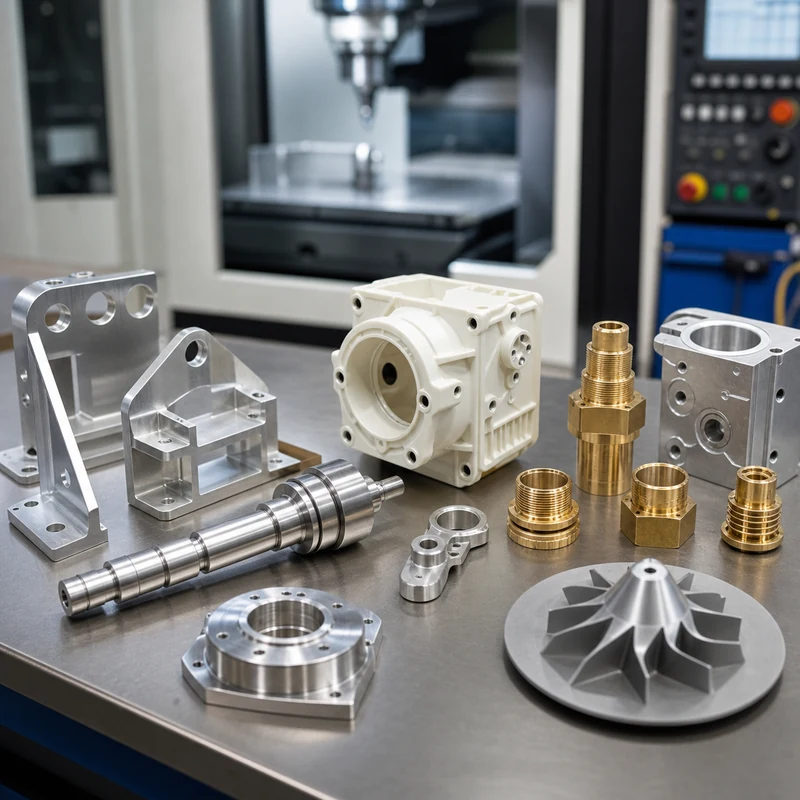
CNC machines can make a wide range of products, from simple plates and brackets to precision housings, shafts, heat sinks, fixtures, molds, connectors, robotic parts, and medical or aerospace components. The same core idea applies across all of them: a digital toolpath controls a cutting process so the finished part matches the model and drawing.

The best CNC product is not defined only by shape. It also depends on material, tolerance, surface finish, quantity, inspection level, and how the part will be assembled. MTSPi supports custom machined parts through CNC machined products, material planning, and production-oriented quality control.

Examples of CNC-Made Products

Product Type Examples Common Process
Structural parts Brackets, plates, frames, mounting blocks, machine bases 3-axis milling, 4-axis milling, 5-axis machining
Rotational parts Shafts, bushings, spacers, collars, rollers, pins CNC turning, Swiss-type machining, mill-turn
Enclosures and housings Sensor housings, electronics cases, motor covers, valve bodies Milling, drilling, tapping, boring
Thermal parts Heat sinks, cold plates, cooling blocks, finned components Milling, drilling, surface finishing
Tooling and fixtures Inspection fixtures, assembly jigs, soft jaws, nests, gauges Milling, turning, grinding-ready machining
Molds and dies Mold inserts, cavities, cores, die details 3-axis and 5-axis milling
Decorative or functional panels Nameplates, engraved plates, dashboard panels, prototypes Milling, engraving, finishing

Parts by Industry

Aerospace and drones

CNC machining can produce lightweight brackets, sensor mounts, landing gear parts, housings, antenna components, and structural frames. Aluminum and titanium are common because weight and strength matter.

Medical and life science

Medical projects often use stainless steel, titanium, aluminum, and engineering plastics for instrument components, housings, fixtures, and test hardware. Inspection, material control, and finish quality are especially important.

Robotics and automation

Robots need accurate joints, grippers, end-effectors, actuator housings, bearing blocks, shafts, sensor mounts, and lightweight plates. CNC machining is useful because fit and repeatability affect motion performance.

Electronics and semiconductor equipment

CNC machines can make enclosures, heat sinks, vacuum-compatible components, connector blocks, precision plates, and fixture hardware for electronics and semiconductor workflows.

Materials Used for CNC Products

  • Aluminum for lightweight prototypes, housings, brackets, and heat sinks.
  • Stainless steel for corrosion-resistant and durable components.
  • Brass and copper for fittings, contacts, thermal parts, and electrical components.
  • PEEK, POM, nylon, ABS, PC, and acrylic for insulated, lightweight, or low-friction parts.

What Cannot Be Made Efficiently With CNC?

CNC machining is not always the best answer. Thin sheet-metal parts may be better suited to laser cutting and bending. Very high-volume plastic parts may justify injection molding. Extremely large cast shapes may need casting first, followed by CNC finishing. The right process depends on geometry, volume, material, and cost target.

Design Tips for CNC-Made Products

  • Use realistic internal radii instead of sharp inside corners.
  • Avoid very deep narrow pockets unless they are functionally necessary.
  • Specify only the tolerances that affect fit, motion, sealing, or inspection.
  • Choose finishes early because anodizing, plating, polishing, and coating change dimensions and appearance.
  • Include drawings for threads, critical dimensions, flatness, surface roughness, and inspection notes.

From Idea to Finished Part

A typical project starts with CAD files and a drawing, then moves through manufacturability review, material selection, machining strategy, finishing, inspection, and shipment. For early-stage designs, rapid prototyping helps test fit and function before committing to a larger production run.

Related MTSPi Resources

FAQ

Can a CNC machine make finished products?

Yes. CNC machines can make finished components and, in some cases, complete products. Many projects still require secondary operations such as finishing, assembly, marking, or inspection.

Is CNC better for metal or plastic parts?

CNC works well for both. The best material depends on strength, weight, temperature, friction, chemical exposure, appearance, and cost.

Categories
Blog CNC Machining Basics Industries & Applications

What Is a CNC Machine Used For? Applications, Parts, and Manufacturing Examples

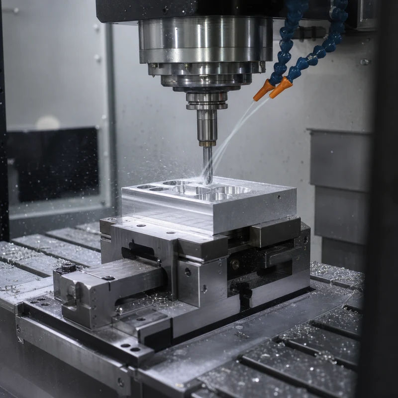
Quick answer: A CNC machine is used to cut, drill, turn, mill, engrave, tap, and shape metal or plastic parts with computer-controlled motion. It is commonly used for prototypes, production parts, fixtures, housings, shafts, brackets, molds, tooling, and precision components.

Common Uses of CNC Machines

CNC machines are used anywhere a part needs repeatable dimensions, controlled surfaces, accurate holes, or consistent production quality. The same basic technology can make a single prototype, a replacement component, or a batch of production parts.

Use Typical parts Best machine route
Prototypes Test housings, brackets, plates, adapters, fixtures CNC milling or turning
Machinery components Shafts, bushings, mounts, plates, tooling blocks Milling, turning, drilling
Aerospace and robotics Lightweight brackets, structural parts, precision interfaces Milling and multi-axis machining
Medical and electronics Small housings, connectors, fixtures, instrument components Precision milling and inspection
Maintenance parts Custom spacers, repair parts, replacement pins, covers Turning, milling, fast turnaround machining

Why Manufacturers Use CNC Instead of Manual Machining

Manual machining depends heavily on operator control. CNC machining uses programmed motion, making it better for repeatability, complex geometry, documented setups, and consistent batches. Manual work still has value for simple repairs, but CNC is stronger when repeatable production or tight drawing control is needed.

What Materials Can CNC Machines Cut?

CNC machines can cut many machining materials, including aluminum, stainless steel, carbon steel, brass, copper, titanium, ABS, POM, nylon, acrylic, PC, and PEEK. Aluminum is common for prototypes and lightweight parts, while stainless steel is selected for strength and corrosion resistance.

Which CNC Process Fits Which Part?

Flat, block-like, pocketed, or bracket-style parts usually fit CNC milling. Round parts such as shafts, pins, spacers, threaded sleeves, and bushings usually fit CNC turning. Parts with both round and milled features may require combined operations.

Industries That Use CNC Machines

  • Automation equipment and robotics
  • Automotive and electric vehicle hardware
  • Aerospace prototypes and lightweight structural parts
  • Medical devices, test fixtures, and instrument components
  • Electronics enclosures, heat sinks, and connectors
  • Industrial machinery, packaging equipment, and tooling

How to Decide If CNC Is Right for Your Part

CNC is a strong choice when you need real material properties, accurate dimensions, functional testing, low-volume production, or a part that cannot be easily molded without tooling. If the design needs very organic geometry or internal channels, 3D printing may be worth comparing.

FAQ

Can a CNC machine make one part?

Yes. CNC machining is often used for one-off prototypes, custom replacement parts, and short-run production.

Can CNC machines make plastic parts?

Yes. CNC machining is common for ABS, POM, nylon, acrylic, PC, PEEK, and other engineering plastics.

What is the difference between CNC milling and CNC turning?

Milling uses rotating cutting tools against a fixed workpiece, while turning rotates the workpiece against cutting tools.

Are CNC machines used for mass production?

Yes, but the economics depend on part geometry, cycle time, fixture design, material, and quantity.

Need help choosing a machining route?

Send MTSPi your drawing, material, quantity, finish, and inspection requirements. We will review the part for manufacturability before quoting.

Contact MTSPi for a CNC machining quote

Practical Buyer Notes

When buyers ask what a CNC machine is used for, the real question is usually whether CNC is the right manufacturing route for a specific part. CNC is strongest when the part needs real engineering material, controlled dimensions, repeatable features, and faster development than mold tooling.

For sourcing decisions, separate prototype use from production use. A prototype may focus on fit and function, while a production order must also consider cycle time, fixture repeatability, inspection method, packaging, and long-term cost stability.

How to Evaluate This Topic on a Real Drawing

Decision point Recommended approach Why it matters
Prototype or production Use CNC for real-material prototypes and low-volume production Avoids tooling cost while keeping functional material properties
Part geometry Match flat parts to milling and round parts to turning The right route lowers setup time and improves accuracy
Assembly risk Mark mating faces, holes, threads, and datums These features usually decide whether the part works
Finish requirement Define cosmetic and protective finishes early Finishing can change appearance, lead time, and dimensions

Common Mistakes to Avoid

  • Treating CNC as one single process instead of choosing milling, turning, drilling, or multi-axis machining.
  • Asking for tight tolerances on every dimension instead of only functional features.
  • Choosing a material by name without checking strength, heat, corrosion, and finish needs.
  • Forgetting to define threads, inserts, cosmetic faces, and burr requirements.

Recommended MTSPi Review Workflow

For application-driven pages, MTSPi reviews the part by use case first, then chooses the machining route. This keeps the page useful for information searches and also helps real buyers understand the quoting path.

  1. Confirm the part function, operating environment, and assembly risk.
  2. Review material, process, tolerance, surface finish, and inspection requirements together.
  3. Separate critical features from general dimensions so cost is not wasted on non-functional details.
  4. Use related resources such as CNC materials, surface treatment, and quality assurance to complete the specification.
  5. Send the final drawing package to MTSPi for quote review before production.

What to Send for a Faster Quote

A faster quote needs more than a screenshot or rough size. The best input package explains what the part does, how it assembles, which features are critical, and what finish or inspection level is required.

  • 3D CAD file and 2D drawing with revision number.
  • Material grade or acceptable alternatives.
  • Quantity, delivery target, and whether samples are required first.
  • Critical dimensions, thread callouts, finish notes, and inspection requirements.
  • Application notes when the part is used in heat, moisture, wear, vibration, or visible assemblies.

Conclusion

A CNC machine is used to turn digital designs into accurate physical parts. The best results come from matching the part shape to the right machining route, choosing a suitable material, and defining the important tolerances clearly before production.

Categories
Blog CNC Materials

What Is Cobalt Used For? Applications, Alloys, Properties, and Machining Notes

Quick answer: Cobalt is used for high-temperature alloys, lithium-ion batteries, magnets, cutting tools, wear-resistant coatings, pigments, catalysts, medical alloys, and corrosion-resistant components. In manufacturing, cobalt is valued for heat resistance, hardness, wear behavior, and alloy performance.

Why Cobalt Is Valuable

Cobalt is a metallic element often used as an alloying ingredient rather than as a pure structural material. It can improve high-temperature strength, hardness, wear resistance, corrosion behavior, and magnetic properties. These characteristics make it important in aerospace, energy, tooling, electronics, and medical applications.

Common Uses of Cobalt

Application Why cobalt is used Manufacturing note
Superalloys High-temperature strength and oxidation resistance Used in demanding turbine and aerospace environments
Batteries Electrochemical performance in certain battery chemistries Often discussed with nickel, lithium, and manganese systems
Magnets Magnetic performance and temperature stability Used in specialized magnetic materials
Cutting tools Hot hardness and wear resistance Cobalt-bearing tool steels and carbides improve cutting durability
Medical alloys Wear and corrosion resistance Requires strict material and quality control

Cobalt in Machining and Tooling

Many machinists know cobalt through cobalt high-speed steel drills and cutting tools. These tools can hold hardness at higher temperatures than ordinary HSS, making them useful for tougher metals when cutting conditions are appropriate.

Is Cobalt Easy to Machine?

Pure cobalt and cobalt-based alloys are not usually selected for easy machining. Many cobalt alloys are tough, heat-resistant, and abrasive to tools. Machining strategy may require rigid workholding, suitable tooling, conservative cutting parameters, coolant control, and careful inspection.

Cobalt Compared with Other Metals

Cobalt is often compared with nickel, titanium, stainless steel, and tool steel in demanding applications. For general CNC components, buyers usually choose a more common machinable metal unless cobalt alloy performance is specifically required.

Buyer Notes for Cobalt-Related Parts

  • Confirm the exact alloy, not just the word cobalt.
  • Define heat treatment and certification requirements.
  • Expect higher tooling difficulty for cobalt-based superalloys.
  • Review surface finish and inspection needs early.
  • Use an experienced supplier for high-value precision parts.

FAQ

Is cobalt a metal?

Yes. Cobalt is a metal and is commonly used as an alloying element in high-performance materials.

What is cobalt mostly used for?

Major uses include batteries, superalloys, magnets, cutting tools, catalysts, pigments, and medical alloys.

Is cobalt used in CNC machining?

Cobalt appears in some machined alloys and in cobalt-containing cutting tools, but many cobalt alloys are challenging to machine.

Is cobalt the same as nickel?

No. Cobalt and nickel are different metals, though they are both used in high-performance alloys and battery-related materials.

Need help choosing a machining route?

Send MTSPi your drawing, material, quantity, finish, and inspection requirements. We will review the part for manufacturability before quoting.

Contact MTSPi for a CNC machining quote

Practical Buyer Notes

Cobalt pages can rank for general science-style searches, but for MTSPi they should connect the material to manufacturing uses. The best content explains cobalt in alloys, cutting tools, batteries, magnets, coatings, and high-temperature applications.

Pure cobalt is not usually the everyday CNC material buyers request. More often, cobalt appears in cobalt-bearing alloys, cobalt chrome, tool steels, carbide tooling, or superalloys. This distinction makes the page more useful and more trustworthy.

How to Evaluate This Topic on a Real Drawing

Decision point Recommended approach Why it matters
Application Explain batteries, magnets, superalloys, tools, and medical alloys Covers broad search intent
Material form Separate pure cobalt from cobalt-containing alloys Prevents misleading manufacturing advice
Machinability Mention toughness, heat resistance, and tool wear Connects the topic to CNC decisions
Buyer action Ask for exact alloy grade and certification needs Improves quote accuracy

Common Mistakes to Avoid

  • Talking about cobalt only as a battery material.
  • Suggesting all cobalt materials machine the same way.
  • Ignoring cobalt chrome, superalloys, and cobalt cutting tools.
  • Leaving out safety, certification, and exact alloy identification.

Recommended MTSPi Review Workflow

When a buyer mentions cobalt, MTSPi should first identify the exact alloy and application. Then the review should cover machinability, heat treatment, certification, surface finish, and inspection requirements.

  1. Confirm the part function, operating environment, and assembly risk.
  2. Review material, process, tolerance, surface finish, and inspection requirements together.
  3. Separate critical features from general dimensions so cost is not wasted on non-functional details.
  4. Use related resources such as CNC materials, surface treatment, and quality assurance to complete the specification.
  5. Send the final drawing package to MTSPi for quote review before production.

What to Send for a Faster Quote

Send the exact alloy grade, drawing, operating temperature, certification requirement, quantity, finish, and whether the part is prototype or production.

  • 3D CAD file and 2D drawing with revision number.
  • Material grade or acceptable alternatives.
  • Quantity, delivery target, and whether samples are required first.
  • Critical dimensions, thread callouts, finish notes, and inspection requirements.
  • Application notes when the part is used in heat, moisture, wear, vibration, or visible assemblies.

Cobalt Alloy Buyer Considerations

When cobalt is part of a machining discussion, the exact alloy matters more than the word cobalt itself. Cobalt chrome, cobalt-bearing tool steel, cobalt-based superalloys, and battery-related cobalt compounds have very different properties and manufacturing requirements. A CNC supplier needs the actual material grade, not only a general material family.

Buyers should also clarify whether the part requires certification, heat treatment, special inspection, or controlled surface finish. Cobalt-related materials are often selected for demanding environments, so unclear specifications can create cost, tooling, and quality risks.

Conclusion

Cobalt is important because it improves performance in demanding environments. For CNC buyers, the key is to identify the exact cobalt alloy, understand machining difficulty, and define quality requirements before production begins.

Categories
Blog CNC Machining Basics Guides Manufacturing Process Comparisons Quality & Tolerances

DMLS Dense Metal Parts: Porosity, HIP, CNC Post-Processing, and Inspection

DMLS can build metal parts with impressive density, but dense does not mean simple. Metal powder quality, laser parameters, scan strategy, part orientation, support design, heat treatment, and inspection all affect the final result. For engineers, the real question is not only whether a part can be printed, but whether it can meet strength, fatigue, sealing, machining, and assembly requirements after printing.

This guide explains how Direct Metal Laser Sintering builds dense metal parts, what creates porosity, how post-processing improves performance, and when CNC machining should be used after printing. It complements MTSPi’s broader DMLS and CNC post-processing guide, but focuses specifically on density, voids, quality control, and functional metal part performance.

What Does Dense Mean in DMLS?

In DMLS, density describes how much of the part volume is solid metal compared with voids, pores, or incomplete fusion areas. A highly dense printed part has very little internal porosity. This matters because pores can reduce strength, fatigue life, pressure tightness, thermal conductivity, and confidence in critical applications.

Bulk density is sometimes reported as a percentage of theoretical density. However, a single number does not tell the whole story. The size, shape, location, and distribution of pores can matter as much as total pore volume. A few pores near a stressed surface or sealing feature may be more important than small isolated pores in a low-stress region.

How DMLS Builds Dense Metal Parts

DMLS uses a laser to fuse thin layers of metal powder. Each layer must melt or sinter consistently enough to bond with the previous layer and neighboring scan tracks. If laser energy is too low, powder may not fully fuse. If energy is too high, vaporization, spatter, or keyhole porosity can occur. Stable density depends on a balanced process window.

Process Factor How It Affects Density Engineering Note
Powder quality Particle size, shape, flowability, oxygen level, and contamination affect fusion Use qualified powder and controlled reuse practices
Laser power and speed Controls melt pool size and bonding between tracks Wrong energy can cause lack of fusion or keyhole pores
Layer thickness Affects resolution, build time, and fusion consistency Thinner layers may improve detail but increase time
Scan strategy Controls heat distribution and overlap Poor strategy can increase distortion or porosity
Shielding gas Limits oxidation and stabilizes the build atmosphere Gas flow and cleanliness matter
Part orientation Changes support needs, thermal behavior, and defect risk Orient parts with post-machining and inspection in mind

Common Types of Porosity

Not all pores have the same cause. Understanding the defect type helps engineers decide whether the issue is a process problem, design problem, material issue, or inspection requirement.

  • Lack-of-fusion porosity happens when powder or scan tracks do not bond completely.
  • Gas porosity can come from trapped gas inside powder particles or the melt pool.
  • Keyhole porosity can occur when excessive energy creates an unstable deep melt pool.
  • Contamination-related pores may appear when powder handling or atmosphere control is poor.
  • Surface-connected porosity may affect sealing, coating, fatigue, or machining results.

DMLS Density vs CNC Machined Metal

CNC machining starts from wrought, cast, forged, or extruded stock. Material density and internal quality depend on that stock form and material certification. DMLS builds the material at the same time it builds the shape, so density depends strongly on the build process. This is why DMLS parts usually need more process qualification than conventional custom CNC machining parts.

Comparison Point DMLS Metal Part CNC Machined Metal Part
Material formation Built layer by layer from powder Cut from existing billet, bar, plate, or casting
Internal defects Porosity and lack of fusion must be controlled Depends on stock quality, inclusions, casting voids, or forging quality
Geometry freedom Excellent for internal channels and lattices Limited by tool access and cutting geometry
Precision surfaces Often require post-machining Can be produced directly with suitable machining strategy
Certification focus Build parameters, powder, heat treatment, density, inspection Material certs, machining inspection, finish, heat treatment if required

Why Dense DMLS Parts Still Need Post-Processing

A dense printed part can still have rough surfaces, residual stress, support marks, dimensional variation, and features that are not accurate enough for assembly. Post-processing turns a good printed blank into a functional part. The exact sequence depends on material and application.

  • Stress relief reduces residual stress from rapid heating and cooling.
  • HIP can close some internal pores and improve fatigue performance for certain applications.
  • Support removal clears anchors and rough attachment areas.
  • CNC machining finishes datums, holes, threads, sealing faces, bearing seats, and flat surfaces.
  • Polishing, blasting, or coating controls surface finish and appearance.
  • Inspection confirms density, dimensions, and functional features.

HIP: Hot Isostatic Pressing and Density Improvement

Hot Isostatic Pressing, or HIP, uses high temperature and high pressure to reduce internal porosity in certain metal parts. It can improve fatigue life, ductility, and reliability when used correctly. HIP is common in aerospace, medical, and high-performance metal additive applications, but it is not a shortcut for poor printing practice.

Design teams should confirm whether HIP is required by the application, material, standard, or customer specification. After HIP, critical features may still need CNC machining because dimensional changes and surface requirements must be controlled.

CNC Machining After DMLS

CNC post-processing is often the practical bridge between additive geometry and precision assembly. DMLS may create an internal cooling channel, lightweight lattice, or complex bracket form, while 5-axis machining or precision milling finishes the surfaces that need to mate with other parts.

  • Machine datums first so later inspection has stable references.
  • Leave machining allowance on printed bosses, pads, holes, and sealing faces.
  • Avoid printing final precision holes unless the tolerance is loose.
  • Tap or thread-machine critical threads after printing.
  • Plan fixturing early because organic DMLS shapes can be hard to hold.
  • Use inspection data to confirm both printed and machined zones.

Design Tips for Dense DMLS Parts

A dense DMLS part starts with good design. If the part traps powder, overheats in thick sections, has unsupported overhangs, or leaves no allowance for machining, density alone will not make it successful.

  • Avoid unnecessary thick masses that create thermal gradients and long build times.
  • Use lattice structures only where they serve load, weight, airflow, or heat-transfer goals.
  • Add powder escape paths for internal cavities.
  • Design supports so they can be removed without damaging functional areas.
  • Separate as-printed surfaces from post-machined precision surfaces on the drawing.
  • Define density, porosity, and inspection requirements only where they matter.
  • Confirm whether the part needs heat treatment, HIP, or surface finishing.

Inspection Methods for Dense Metal Printed Parts

DMLS inspection can include dimensional checks, visual review, microscopy, density measurement, CT scanning, metallography, tensile coupons, hardness testing, and surface roughness measurement. For many projects, inspection should be matched to risk. A concept prototype may only need basic measurement. A pressure part, medical part, or aerospace bracket may need a much stronger quality assurance plan.

Inspection Method What It Checks When It Helps
Dimensional inspection Size, flatness, position, machined features Almost every functional part
CT scanning Internal pores, cracks, trapped powder, channels Complex or critical internal geometry
Metallography Microstructure, fusion quality, pores Process validation and high-risk parts
Tensile coupons Strength, elongation, material response Material qualification and critical builds
Surface roughness testing As-printed or machined surface condition Sealing, fatigue, flow, and cosmetic surfaces

Applications Where Density Matters

Density matters most when a part carries load, sees fatigue, holds pressure, transfers heat, or must pass strict validation. Examples include aerospace brackets, medical implants or instruments, heat exchangers, manifolds, tooling inserts with conformal cooling, lightweight robotic structures, and high-performance prototypes.

For less critical visual prototypes, density may be less important than appearance, geometry, and lead time. In those cases, polymer printing, CNC machining, or rapid prototyping with another process may be more practical.

When to Choose CNC Instead of DMLS

If a part is a simple bracket, plate, shaft, housing, or block with accessible features, CNC machining is usually the stronger first option. It typically offers better surface finish, tighter tolerances, broader material availability, and lower cost for conventional geometry. DMLS becomes more attractive when geometry complexity is doing real work.

For conventional metal parts, compare aluminum CNC machining, stainless steel CNC machining, titanium CNC machining, and other material options before committing to metal additive manufacturing.

How MTSPi Can Support Dense DMLS Projects

MTSPi focuses on CNC machining, rapid prototyping, materials guidance, surface finishing, and inspection support. If a project uses DMLS for complex geometry, MTSPi can help review the post-machined features: datums, holes, threads, sealing areas, pads, tolerances, finish requirements, and inspection needs.

Send your CAD model, drawing, material requirements, expected load case, quantity, post-machining notes, and inspection requirements through the contact page. We can help decide which surfaces should be printed, which should be machined, and where design allowances are needed.

FAQ

Can DMLS parts be as dense as wrought metal?

DMLS parts can reach high density, but equivalence to wrought metal depends on material, process qualification, heat treatment, HIP, orientation, and inspection. Critical applications should not rely on generic claims alone.

What is the biggest risk with DMLS density?

The biggest risk is hidden porosity or lack of fusion in a functional area, especially near loaded surfaces, pressure boundaries, sealing faces, or fatigue-critical regions.

Does HIP remove all porosity?

HIP can reduce or close certain internal pores, but it does not replace proper process control, design review, support strategy, and inspection.

Should DMLS holes be printed or machined?

Loose clearance holes may be printed, but precision holes, threaded holes, reamed holes, and sealing bores are usually better machined after printing.

Is DMLS good for production parts?

DMLS can be used for production when geometry, quantity, material, certification, and inspection requirements justify it. For simple shapes, CNC machining is often more practical.

Can MTSPi machine DMLS printed blanks?

MTSPi can support CNC post-processing planning for printed blanks, including machined datums, holes, threads, sealing surfaces, finishing, and inspection requirements.

Categories
Blog Design, Cost & Sourcing Guides Manufacturing Process Comparisons

Sheet Metal Part Design Mistakes: DFM Checklist for Better Parts

Sheet metal parts look simple on a screen, but small design mistakes can create big problems during laser cutting, bending, hardware insertion, welding, finishing, and assembly. A hole placed too close to a bend may distort. A missing bend relief may tear. A coating may close up a tight slot. A U-shaped channel may flex even though the material looks thick enough.

This guide rewrites the common sheet metal design mistakes into a practical DFM checklist for engineers, product developers, and sourcing teams. It also connects sheet metal decisions with rapid prototyping, CNC machining, material selection, and surface treatment, because many real parts combine fabrication, machining, inserts, finishing, and inspection.

Quick Checklist: Sheet Metal Design Mistakes to Avoid

Mistake What Can Go Wrong Better Design Habit
No true sheet metal model or flat pattern Bends, reliefs, and blank size may be wrong Use CAD sheet metal features and export a clean flat pattern
Holes too close to bends Holes stretch, become oval, or interfere with tooling Keep cutouts away from bend lines and confirm supplier rules
Sharp perpendicular corners Stress concentration, cracking, poor finish, higher tooling risk Use radii and bend relief where the material changes direction
Missing hardware details Wrong PEM nut, standoff, thread, or clearance Specify hardware type, size, material, and installation side
Finish chosen too late Coating affects dimensions, masking, color, or corrosion performance Plan finishing before tolerances are frozen
Wrong material or thickness Part bends too easily, cracks, costs too much, or cannot be formed Choose material by strength, bendability, corrosion, and finish
Weak U-channel or long unsupported flange Part twists, opens, vibrates, or deforms in assembly Add returns, ribs, hems, beads, or thicker material
Welds or fasteners are inaccessible Assembly is slow, inconsistent, or impossible Check tool access, torch access, screw access, and inspection access

Mistake 1: Designing Without Sheet Metal Features

A common issue is modeling the part as a solid block instead of a true sheet metal component. Sheet metal parts must unfold into a flat blank, then bend into the final shape. If the CAD model does not define thickness, bend radius, relief, K-factor, and bend direction, the manufacturer may have to reinterpret the design before quoting or production.

Use sheet metal tools in CAD whenever possible. Confirm that the part can flatten cleanly, that bends are consistent, and that the flat pattern matches the intended manufacturing method. If the part includes machined areas, inserts, or welded elements, mark them separately instead of hiding everything inside a generic 3D model.

Mistake 2: Placing Holes Too Close to Bend Lines

Holes, slots, vents, and cutouts near a bend line can stretch or distort during forming. Round holes may become oval, slots may pull out of shape, and countersinks may become unusable. The problem becomes more visible in thicker material, tighter bend radii, and harder alloys.

  • Move holes away from bend lines when the hole shape must stay accurate.
  • Use bend relief if a cutout must approach a formed edge.
  • Confirm whether holes should be cut before bending or machined after bending.
  • Leave room for tooling, punch clearance, hardware heads, and inspection gauges.

Mistake 3: Using Sharp Corners Where Radii Are Needed

Sharp internal corners create stress concentration and can be difficult to cut, bend, weld, polish, or coat. In sheet metal, sharp corners also increase the chance of tearing around bends or creating burr-heavy edges. A small radius often improves both function and manufacturability.

For laser-cut profiles, corner radii can reduce burr risk and coating build-up. For formed features, realistic bend radii prevent cracking and improve repeatability. If a sharp corner is functional, identify only that area instead of making every corner unnecessarily sharp.

Mistake 4: Forgetting Bend Relief and Flange Rules

Bend relief prevents tearing and unwanted deformation where a bend ends near an edge or another feature. Flanges also need enough length for tooling to grip and form the part. If a flange is too short, the part may not bend consistently or may require special tooling.

Design Area Risk DFM Check
Bend relief Tearing or bulging near bend ends Add relief slots or notches where needed
Minimum flange length Tooling cannot form the bend reliably Check against material thickness and bend tooling
Bend radius Cracking or inaccurate angle Use standard inside radii where possible
Bend sequence Earlier bends block later bends Review whether tooling can reach each bend

Mistake 5: Not Specifying Hardware Correctly

Self-clinching nuts, studs, standoffs, threaded inserts, rivets, weld nuts, and fasteners are common in sheet metal assemblies. If the drawing only says insert nut here, the supplier may not know the required thread, material, installation side, flange clearance, plating compatibility, or pull-out strength.

  • Specify hardware part number or an approved equivalent.
  • Show installation side and orientation clearly.
  • Confirm hole size and sheet thickness range for the hardware.
  • Keep hardware away from bends, edges, and other fasteners unless clearance is verified.
  • Consider plating or coating after hardware insertion if conductivity or masking matters.

Mistake 6: Choosing Finish After the Design Is Finished

Surface treatment should be considered early. Powder coating, anodizing, plating, black oxide, passivation, painting, and polishing all affect cost, lead time, appearance, corrosion resistance, and sometimes dimensions. A coating can close up small holes or slots. Masking may be needed for threads, electrical contact, grounding areas, or bearing surfaces.

If the part combines sheet metal and machined elements, finishing becomes even more important. Review finish requirements with surface treatment planning before locking the drawing.

Mistake 7: Choosing the Wrong Material or Thickness

Material choice controls strength, stiffness, bendability, corrosion resistance, weight, cost, and finish options. Aluminum is lightweight and corrosion resistant but softer than steel. Mild steel is economical and strong but needs corrosion protection. Stainless steel resists corrosion but may cost more and be harder to form. Copper and brass bring electrical, thermal, or cosmetic value but require their own design allowances.

Material Good For Watch Points
Aluminum sheet Lightweight brackets, covers, panels, enclosures Softer threads, bend cracking in some tempers, anodizing allowance
Mild steel Strong economical brackets, frames, fixtures Rust protection required
Stainless steel Corrosion-resistant covers, medical or food equipment, outdoor hardware Higher cost and springback
Copper Electrical and thermal parts Softness, scratching, bend control
Brass Decorative or electrical components Cost, forming limits, finish sensitivity

For broader metal comparison, use the CNC metal machining and materials pages as supporting resources when the part includes both formed and machined features.

Mistake 8: Making U-Channels and Long Flanges Too Weak

U-shaped channels, C-shaped brackets, and long unsupported flanges can look strong in CAD but twist or open under load. The problem is common in enclosures, rails, mounting brackets, and covers. Thin sheet with a long flange may vibrate, oil-can, or deform during assembly.

  • Add return flanges to increase stiffness.
  • Use ribs, beads, gussets, hems, or formed features where allowed.
  • Increase thickness only after checking cost and bend feasibility.
  • Reduce unsupported span when possible.
  • Use spot welds, fasteners, or machined reinforcements when needed.

Mistake 9: Ignoring Welding and Assembly Access

A part can be manufacturable as a single piece but difficult to weld, fasten, inspect, or service. Weld guns, torches, clamps, screwdrivers, rivet tools, and gauges all need access. If access is blocked by a flange or enclosure wall, the assembly may become slow or impossible to build consistently.

Before releasing drawings, review the actual build order. Which bend happens first? When is hardware installed? Can the part be clamped for welding? Can a screw be tightened? Can a gauge reach the feature after assembly? These questions prevent expensive late-stage redesign.

Mistake 10: Treating Every Dimension as Critical

Over-tolerancing sheet metal can raise cost without improving function. Formed parts naturally have more variation than machined parts because bend angle, springback, grain direction, tooling, and material batch affect the result. Critical mating features should be controlled, but non-critical overall dimensions often need more practical tolerances.

If a feature truly needs high precision, consider whether it should be machined after forming or designed as a separate CNC component. MTSPi can support related 3-axis machining, 5-axis machining, and inspection planning for hybrid parts.

A Practical Sheet Metal DFM Workflow

  • Start with function: load, appearance, environment, assembly, and service access.
  • Choose material and thickness before finalizing bends and hardware.
  • Use proper sheet metal CAD features and check the flat pattern.
  • Verify bend radius, bend relief, flange length, and hole-to-bend distance.
  • Specify hardware, threads, inserts, welds, and finish requirements clearly.
  • Review coating thickness, masking, and corrosion protection.
  • Separate critical tolerances from non-critical reference dimensions.
  • Prototype high-risk designs before ordering larger batches.

How MTSPi Helps With Sheet Metal and CNC-Related Parts

MTSPi mainly supports CNC machining, rapid prototyping, materials guidance, finishing, and inspection for custom parts. Many customer projects include sheet metal enclosures, brackets, machined inserts, shafts, plates, and hardware that must fit together. We can review drawings for manufacturability, CNC features, finish planning, assembly risks, and inspection requirements.

For a sheet metal or hybrid CNC project, send your 3D model, flat pattern, 2D drawing, material, thickness, quantity, finish, and hardware notes through the contact page. The earlier DFM feedback happens, the easier it is to avoid expensive design revisions.

FAQ

What is DFM for sheet metal?

DFM for sheet metal means designing parts so they can be cut, bent, formed, finished, assembled, and inspected reliably with practical tooling and tolerances.

Why do holes distort near bends?

Material stretches and compresses during bending. If a hole or slot is too close to the bend line, the forming process can pull it out of shape.

Should sheet metal parts have sharp corners?

Sharp corners should be avoided unless they are functional. Radii reduce stress concentration, improve finishing, and often make cutting and forming more reliable.

When should hardware be specified on the drawing?

Hardware should be specified before quoting and production, including thread size, part number or equivalent, installation side, hole size, material, and finish requirements.

Can sheet metal parts be combined with CNC machined parts?

Yes. Many assemblies combine sheet metal covers or brackets with CNC machined blocks, shafts, spacers, inserts, and precision mounting features.

Can MTSPi review sheet metal designs for manufacturability?

MTSPi can review CNC-related features, materials, finishing, assembly risks, and inspection needs for sheet metal and hybrid custom-part projects.

Categories
Blog CNC Machining Basics Guides Manufacturing Process Comparisons

Direct Metal Laser Sintering (DMLS): Metal 3D Printing and CNC Post-Processing Guide

Direct Metal Laser Sintering, commonly shortened to DMLS, is a metal 3D printing process used to build complex metal parts directly from digital CAD data. Instead of cutting material away from a billet, DMLS fuses fine metal powder layer by layer with a high-energy laser. The result can be a dense metal part with shapes that would be difficult, expensive, or impossible to make with conventional machining alone.

For engineers sourcing prototypes or low-volume parts, DMLS should not be viewed as a replacement for every CNC machined component. It is a complementary process. The strongest projects use each method where it makes sense: DMLS for design freedom and complex forms, then CNC machining, turning, finishing, and inspection for critical surfaces.

What Is Direct Metal Laser Sintering?

DMLS is a powder-bed fusion process. A thin layer of metal powder is spread across a build platform. A laser traces the cross-section of the part and fuses selected areas. The platform lowers, a new powder layer is applied, and the process repeats until the full part is built. After printing, loose powder is removed and the part is separated from the build plate.

The process is often grouped with metal 3D printing, selective laser melting, and laser powder bed fusion. Naming can vary by machine supplier and material system, but the practical idea is the same: create metal geometry layer by layer from powder and laser energy.

How DMLS Works Step by Step

  • A 3D CAD model is prepared and oriented for printing.
  • Support structures are added where needed to anchor the part and control heat distortion.
  • A thin metal powder layer is spread across the machine bed.
  • The laser fuses the cross-section of the part in that layer.
  • The build platform lowers and the next powder layer is applied.
  • The completed part is cooled, removed from the powder, and cut from the build plate.
  • Post-processing such as heat treatment, support removal, CNC machining, polishing, blasting, or inspection is completed.

DMLS Materials

DMLS is commonly used with metal materials such as stainless steel, aluminum alloys, titanium alloys, cobalt chrome, nickel alloys, maraging steel, and tool steel depending on supplier capability. The right material depends on strength, weight, corrosion resistance, temperature, fatigue, biocompatibility, and finishing requirements. For machined alternatives, compare options in MTSPi’s CNC machining materials library.

Material Family Why It Is Used in DMLS CNC Selection Note
Stainless steel Corrosion resistance and general mechanical strength CNC may be better for simple shafts, fittings, plates, and precision faces
Aluminum alloys Lightweight functional prototypes and aerospace-style parts CNC aluminum is often faster and smoother for conventional geometry
Titanium alloys High strength-to-weight ratio and medical or aerospace applications CNC titanium can finish critical surfaces after printing
Nickel alloys Heat and corrosion resistance Post-machining may be required for mating surfaces and tight features
Tool or maraging steel High strength tooling, inserts, and conformal cooling concepts Heat treatment and final machining must be planned carefully

Advantages of DMLS

  • Can produce complex internal channels, lattice structures, and lightweight forms.
  • Reduces assembly count by combining several parts into one printed component.
  • Useful for functional metal prototypes without hard tooling.
  • Supports design iterations before casting, forging, or machining strategy is finalized.
  • Can create conformal cooling channels, medical structures, aerospace brackets, and custom tooling inserts.

Limitations of DMLS

  • Surface finish is usually rougher than CNC machining unless post-processed.
  • Tolerances may not match precision machining on critical holes, flats, threads, and sealing areas.
  • Support structures can leave marks and require removal.
  • Build orientation affects strength, surface quality, support needs, and dimensional accuracy.
  • Material choices are narrower than conventional CNC stock materials.
  • Simple prismatic or turned parts are often cheaper and faster by CNC machining.

DMLS vs CNC Machining

DMLS and CNC machining solve different problems. DMLS creates geometry by adding material, so it is excellent when the geometry is complex. CNC machining removes material from solid stock, so it is excellent when the part needs accurate surfaces, holes, threads, flatness, repeatability, and a broad material choice.

Decision Point Choose DMLS When Choose CNC Machining When
Geometry Internal channels, lattice structures, organic shapes, topology-optimized parts Prismatic parts, shafts, plates, housings, brackets, pockets, threaded features
Tolerance Moderate tolerance is acceptable or post-machining is planned Tight dimensions, datums, flatness, bore accuracy, and threads are critical
Surface finish As-printed or blasted surface is acceptable Smooth machined, polished, anodized, plated, or sealing surfaces are required
Quantity Complex prototypes or specialized low-volume components Prototypes through production batches with repeatable geometry
Cost Complexity justifies the process Geometry is simple enough to machine efficiently

For conventional metal prototypes, rapid prototyping through CNC machining is often the more practical choice. For complex parts with internal channels or lightweight structures, DMLS may be better first, followed by CNC post-processing.

When DMLS Parts Need CNC Post-Processing

Many DMLS parts are not finished when they leave the printer. Support removal and heat treatment are common, and precision features often need secondary machining. A printed bracket may need CNC-milled mounting faces. A printed manifold may need reamed holes, tapped ports, or machined sealing surfaces. A printed insert may need ground or polished functional areas.

  • Machine flat datum surfaces that locate the part in an assembly.
  • Drill, ream, or bore precision holes after printing.
  • Tap threads instead of relying only on printed thread geometry.
  • Machine sealing surfaces and bearing seats.
  • Use polishing, blasting, or coating to control surface finish.
  • Inspect critical features with gauges, CMM, or optical methods.

Design Rules for DMLS Parts

Designing for DMLS is different from designing for CNC machining. A geometry that prints well may be difficult to inspect or post-machine. A geometry that machines well may not use the full value of additive manufacturing. The best design considers both printing and secondary operations from the beginning.

  • Avoid unnecessary solid mass; use ribs, shells, or lattice only where they support function.
  • Plan support access and removal before approving the design.
  • Add machining allowance on critical faces, holes, and sealing areas.
  • Orient the part to balance accuracy, surface finish, strength direction, and support requirements.
  • Avoid enclosed powder traps unless powder removal is designed into the part.
  • Mark post-machined features clearly on the drawing.
  • Define inspection requirements for functional surfaces rather than over-tolerancing the whole part.

Tolerances and Surface Finish

DMLS tolerances depend on machine, material, part size, orientation, heat treatment, and post-processing. Small details can be impressive, but precision mating features usually need machining. Surface finish is also process-dependent. As-printed metal surfaces often have a granular texture, while machined faces are smoother and more dimensionally controlled.

If the part needs a controlled finish, consider the full process route: print, stress relieve, remove supports, CNC machine, inspect, then apply finishing if needed. For finish options on metal parts, see MTSPi’s surface treatment guide.

Common Applications

DMLS is useful where geometry complexity creates real value. Typical applications include aerospace brackets, lightweight robotic parts, conformal cooling inserts, medical implants or instruments, custom manifolds, heat exchangers, complex housings, and low-volume metal prototypes.

In many of these applications, DMLS and CNC are combined. A lightweight printed shape may still need 5-axis machining to finish complex datum surfaces or angled features. A printed round feature may need turning or grinding for final fit.

Cost Drivers in DMLS

  • Build volume and part height affect machine time.
  • Material powder cost varies significantly by alloy.
  • Support structures add build time and removal labor.
  • Heat treatment, HIP, machining, polishing, and inspection add cost.
  • Poor orientation can increase supports, distortion, and post-processing difficulty.
  • A part designed like a conventional machined block may waste the benefits of DMLS.

How to Decide Between DMLS, CNC, and Hybrid Manufacturing

Start with the function. If the part is a simple plate, bracket, shaft, spacer, or housing with accessible features, CNC machining is usually the first option to quote. If the part has internal flow channels, impossible undercuts, topology-optimized load paths, or a design that combines many parts into one, DMLS becomes more attractive.

For the strongest decision, split the part into functional zones. Which surfaces need precision? Which areas carry load? Which areas only need clearance? Which features can remain as-printed? Which features must be machined after printing? This approach avoids paying for unnecessary precision while protecting the features that actually matter.

How MTSPi Can Support DMLS-Related Projects

MTSPi focuses on custom CNC machining, rapid prototyping, surface finishing, and inspection support. Even when a project starts with metal 3D printing, CNC post-processing may be required to turn the printed blank into a functional assembly-ready part. MTSPi can help review drawings for machined datums, holes, threads, sealing faces, finish requirements, and inspection planning.

If your project is comparing metal 3D printing and machining, send your CAD model, drawing, material requirements, quantity, tolerance notes, and application details through the contact page. We can help identify which features should be printed, which should be CNC machined, and where design changes may reduce risk.

FAQ

What is DMLS used for?

DMLS is used for complex metal prototypes and low-volume parts such as lightweight brackets, manifolds, conformal cooling inserts, medical structures, aerospace components, and custom tooling.

Is DMLS the same as SLS?

They are related powder-bed processes, but SLS is often used for polymers while DMLS refers to metal powder fusion. Naming varies across suppliers, so material and process details should be confirmed.

Are DMLS parts fully dense?

DMLS parts can achieve high density when processed correctly, but final properties depend on material, machine parameters, orientation, heat treatment, and quality control.

Can DMLS make threads?

Threads can sometimes be printed, but functional precision threads are often tapped or machined after printing for better accuracy and strength.

When is CNC machining better than DMLS?

CNC machining is usually better for simple geometry, tight tolerance, smooth finish, broad material selection, and repeatable production at lower cost.

Can MTSPi machine DMLS parts after printing?

MTSPi can support CNC post-processing considerations such as machined faces, holes, threads, datum surfaces, finishing, and inspection planning for metal prototype projects.

Categories
Blog CNC Materials Design, Cost & Sourcing

Properties of Mild Steel: CNC Machining Material Guide

Mild steel is one of the most widely used metals in manufacturing because it offers a practical balance of strength, cost, machinability, weldability, and availability. For CNC machined parts, it is often selected when the design needs a tough and economical steel component but does not require the corrosion resistance of stainless steel or the low weight of aluminum.

This guide explains the properties of mild steel from a custom-part perspective: what it is, how it behaves during CNC machining, when to choose it, when to avoid it, and which finishes can protect it. If you are comparing steel, aluminum, stainless steel, brass, copper, titanium, or engineering plastics, MTSPi’s CNC machining materials section can help you narrow the choice.

What Is Mild Steel?

Mild steel is a low-carbon steel. It normally contains a relatively small amount of carbon compared with medium-carbon or high-carbon steel, which makes it easier to form, weld, cut, drill, mill, turn, and fabricate. The low carbon level also makes mild steel less brittle and more forgiving in many general-purpose mechanical applications.

Because mild steel is economical and widely available in plate, bar, rod, tube, sheet, and structural forms, it is used across machinery, automation, tooling, automotive components, construction hardware, fixtures, frames, brackets, and equipment parts.

Key Properties of Mild Steel

Property Typical Behaviour Why It Matters for CNC Parts
Strength Moderate strength for general mechanical use Suitable for brackets, fixtures, plates, spacers, shafts, and frames
Ductility Can deform before fracture Useful when parts need toughness instead of brittle failure
Machinability Generally practical to mill, drill, tap, and turn Good for custom CNC parts when tools, feeds, and coolant are controlled
Weldability Usually easier to weld than higher-carbon steels Good for machined-and-welded assemblies
Formability Can be bent and formed in many sheet or plate applications Useful for combined machining and fabrication projects
Corrosion resistance Low compared with stainless steel Often needs coating, plating, oil, paint, or black oxide
Cost Usually lower than stainless steel, titanium, and many specialty alloys Good choice for cost-sensitive parts

Mild Steel vs Carbon Steel

Mild steel is part of the broader carbon steel family. Carbon steel includes low-carbon, medium-carbon, and high-carbon grades. Mild steel usually refers to the low-carbon end of that range. As carbon content increases, steel can become stronger and harder, but it may also become less ductile, less weldable, and more demanding to machine or heat treat.

For many CNC projects, the exact grade matters more than the general name. A drawing should specify the material grade, standard, heat treatment condition, and finish requirements when mechanical performance is important.

Mild Steel vs Stainless Steel

Comparison Point Mild Steel Stainless Steel
Corrosion resistance Rusts easily without protection Much better corrosion resistance depending on grade
Cost Usually more economical Typically higher material and machining cost
Machinability Often easier and faster to machine Can work harden and may require slower machining
Appearance Needs coating or finishing for long-term clean appearance Can remain bright or passivated in many environments
Best use General mechanical, structural, fixture, and cost-sensitive parts Corrosive, hygienic, marine, medical, or food-related environments

If corrosion resistance is a key requirement, stainless steel CNC machining may be a better fit. If the part will be painted, plated, powder coated, or used indoors, mild steel may offer better value.

Mild Steel vs Aluminum

Aluminum is lighter and naturally more corrosion resistant than mild steel, while mild steel is usually stronger, stiffer, and more economical for many load-bearing components. Aluminum often wins when weight, speed of machining, heat dissipation, or anodized appearance matter. Mild steel often wins when cost, stiffness, weldability, and general mechanical robustness matter. See aluminum CNC machining for comparison context.

Is Mild Steel Good for CNC Machining?

Yes. Mild steel is a common CNC machining material for both prototypes and production parts. It can be milled, turned, drilled, tapped, bored, reamed, and surface finished. It is especially useful for parts that need practical strength, threaded holes, flat plates, shafts, brackets, spacers, machine fixtures, and weldable assemblies.

  • CNC milling: suitable for plates, brackets, fixture blocks, mounting features, slots, and pockets.
  • CNC turning: suitable for shafts, pins, bushings, collars, threaded parts, and round spacers.
  • Drilling and tapping: practical for mounting holes and threaded interfaces.
  • Grinding or finishing: useful when better flatness, surface finish, or fit is required.

For part geometry that uses pockets, precision holes, or mating surfaces, CNC milling can provide accurate features. For round parts, pins, shafts, and threaded components, CNC turning may be more efficient.

Advantages of Mild Steel

  • Lower material cost compared with many stainless steels, titanium alloys, and specialty metals.
  • Good availability in many stock forms and thicknesses.
  • Useful strength and stiffness for general engineering parts.
  • Good weldability for fabricated assemblies.
  • Predictable machining behaviour for many common grades.
  • Compatible with many protective finishes.

Limitations of Mild Steel

  • Rusts quickly if exposed to moisture without protection.
  • Heavier than aluminum and many engineering plastics.
  • Not ideal for sanitary, marine, chemical, or outdoor environments unless coated properly.
  • Not as strong or wear-resistant as heat-treated alloy steels.
  • Can require deburring, edge protection, and post-processing to meet cosmetic expectations.

Common Grades and Similar Materials

Grade names vary by region and standard, so sourcing teams should confirm the exact specification on the drawing or purchase order. Common mild steel or low-carbon steel choices may include grades used for general fabrication, machining, plate work, or structural applications. Equivalent grades are not always identical across standards, so final selection should be verified against mechanical and chemical requirements.

Material Type Typical Use Selection Note
Low-carbon steel bar Turned shafts, pins, spacers, collars Good for economical machined round parts
Mild steel plate Brackets, fixture plates, mounting bases Check flatness, thickness tolerance, and surface condition
Cold rolled steel Parts needing better surface finish and tighter stock tolerance Often cleaner for precision plates and small components
Hot rolled steel Frames, large plates, structural parts Scale and surface condition may require machining or blasting
Free-machining steel High-volume turned parts Improves machinability but may affect weldability or compliance requirements

Surface Treatment for Mild Steel

Because mild steel rusts, finishing is often part of the design decision. A part used indoors may only need oil, black oxide, or paint. A visible product part may need powder coating or plating. A part exposed to moisture may need zinc plating, nickel plating, e-coating, or a more corrosion-resistant base material. MTSPi’s surface treatment section covers common finishing options for CNC parts.

Finish What It Does Typical Mild Steel Use
Black oxide Adds a dark appearance and light corrosion resistance with oil Tooling, fixtures, machine parts
Zinc plating Improves corrosion resistance at low cost Fasteners, brackets, hardware
Nickel plating Improves wear, appearance, and corrosion resistance Precision parts, shafts, decorative or functional surfaces
Powder coating Durable colored protective coating Frames, covers, brackets, equipment panels
Painting Economical corrosion and appearance protection Large fabricated or structural parts

Design Tips for CNC Machined Mild Steel Parts

  • Specify the exact grade and standard when strength or compliance matters.
  • Add realistic radii to internal corners to reduce stress concentration and machining cost.
  • Avoid unnecessary tight tolerances on non-critical faces.
  • Call out threaded holes, reamed holes, bearing fits, and datum surfaces clearly.
  • Plan coating thickness if the part has mating surfaces, sliding fits, or threads.
  • Use stainless steel or plating when corrosion is a serious risk.
  • Review welding sequence and post-weld machining needs for assemblies.

Typical Applications

Mild steel is often selected where the part needs strength, stiffness, weldability, and affordability more than light weight or corrosion resistance. It appears in machine bases, tooling plates, brackets, frames, fixture components, pins, collars, shafts, mounting hardware, guards, covers, and general industrial parts.

Industries such as automation, machinery, automotive equipment, robotics fixtures, and industrial hardware often use mild steel when a practical and economical metal is needed. For application-specific support, see MTSPi’s CNC machining applications.

When Should You Avoid Mild Steel?

Mild steel may not be the best option for parts that operate outdoors, in salt spray, in chemical exposure, in medical environments, in food-contact areas, or where low weight is essential. It may also be unsuitable when the part requires very high strength, high hardness, high fatigue resistance, or excellent corrosion resistance without coating.

In those cases, consider stainless steel, aluminum, alloy steel, titanium, brass, copper, or engineering plastics depending on the functional requirement.

How MTSPi Supports Mild Steel CNC Machining

MTSPi can machine mild steel parts from drawings and 3D models for prototypes, low-volume production, fixtures, brackets, shafts, plates, and mechanical components. We can review part geometry, tolerance, surface finish, coating needs, and inspection requirements before production.

To request a quote, send your CAD file, 2D drawing, quantity, steel grade preference, finish requirement, and application notes through the contact page. If you are unsure whether mild steel, stainless steel, or aluminum is better, include the operating environment and load requirements so the material choice can be reviewed.

FAQ

What is mild steel made of?

Mild steel is mainly iron with a low amount of carbon, plus small amounts of other elements depending on the grade and standard.

Does mild steel rust?

Yes. Mild steel can rust when exposed to moisture or corrosive environments, so protective finishing is often required.

Is mild steel easy to machine?

Many mild steel grades are practical to CNC machine. Tooling, coolant, feeds, speeds, chip control, and grade selection still matter for finish and dimensional stability.

Is mild steel stronger than aluminum?

Mild steel is usually stronger and stiffer than common aluminum alloys, but aluminum is much lighter and often easier to machine quickly.

Can mild steel be used for precision parts?

Yes, mild steel can be used for precision components when the grade, stock condition, machining process, tolerances, and finishing are specified correctly.

Can MTSPi machine mild steel prototypes and production parts?

Yes. MTSPi supports CNC machined mild steel prototypes, fixtures, brackets, shafts, plates, and low-volume production parts.

Categories
Blog CNC Materials Quality & Tolerances

Understanding Yield Strength: A Practical Guide for CNC Machined Parts

Yield strength is one of the most useful material properties for engineers who design custom CNC machined parts. It tells you how much stress a material can take before it stops behaving elastically and starts to deform permanently. In practical terms, it helps answer a direct question: will this bracket, shaft, housing, fixture, or plastic component keep its shape under real load?

This guide explains yield strength in plain engineering language, then connects it to CNC material selection, part geometry, safety factors, machining process choices, and inspection planning. If you are choosing between aluminum, stainless steel, brass, copper, titanium, Delrin, nylon, or PEEK, MTSPi’s CNC machining materials library and custom CNC machining services can help review the application before production.

What Is Yield Strength?

Yield strength is the stress at which a material begins to change shape permanently. Before this point, the material is in the elastic region: it can stretch, bend, or compress slightly and then return to its original shape when the load is removed. After the yield point, plastic deformation begins. The part may still be intact, but it no longer returns fully to its original dimensions.

For a CNC machined component, that distinction matters. A part does not need to break to fail. A bent mounting bracket, an ovalized bore, a stretched fastener area, or a shaft with permanent deflection can cause assembly problems even if the material has not fractured.

Yield Strength vs Tensile Strength

Property What It Means Why It Matters in CNC Part Design
Yield strength Stress where permanent deformation begins Used to prevent bending, stretching, or dimensional loss under working load
Ultimate tensile strength Maximum stress before fracture during tensile loading Useful for understanding final failure capacity
Elastic modulus Material stiffness in the elastic region Controls deflection before yield
Elongation How much the material can stretch before breaking Helps evaluate ductility and toughness
Hardness Resistance to indentation or surface wear Useful for wear surfaces, tooling contact, and finish expectations

A material can have high tensile strength but still yield earlier than expected under design loads. For many structural CNC parts, yield strength is often more important than ultimate strength because the part must maintain alignment, flatness, clearance, and function.

Stress, Strain, and the Yield Point

Stress is the force applied over an area. Strain is the amount of deformation that results from that stress. During a tensile test, a sample is pulled until it stretches and eventually breaks. The stress-strain curve shows how the material behaves from elastic deformation through yielding and final fracture.

Many metals have a visible transition from elastic to plastic behavior. Some materials do not show a sharp yield point, so engineers use an offset yield strength, commonly based on a defined amount of permanent strain. This creates a consistent way to compare materials even when the curve is gradual.

Why Yield Strength Matters for CNC Machined Parts

  • It helps prevent permanent bending in brackets, plates, arms, and frames.
  • It supports shaft, pin, and fastener-area sizing under mechanical load.
  • It helps engineers choose between aluminum, steel, stainless steel, titanium, and engineering plastics.
  • It affects whether a part can survive clamping, press fits, assembly forces, and service loads.
  • It informs safety factors when parts are used in machinery, automation, robotics, aerospace, or medical equipment.

For example, a lightweight aluminum prototype may be suitable for a visual housing, while a loaded fixture plate may need a stronger aluminum alloy, stainless steel, or a design with thicker ribs. A turned shaft may need both yield strength and surface hardness, which makes CNC turning, material grade, heat treatment, and finishing all part of the same decision.

How Yield Strength Is Tested

Yield strength is usually measured with a tensile test. A standardized specimen is clamped in a testing machine and pulled at a controlled rate. The machine records force and elongation, which are converted into stress and strain. The resulting curve shows elastic behavior, yield, strain hardening, and eventual fracture.

For sourced CNC parts, the machine shop normally does not test every machined part for yield strength. Instead, the value usually comes from material standards, mill certificates, supplier data sheets, or customer-specified requirements. Critical projects may require material certificates, hardness checks, dimensional inspection, or additional validation testing.

Typical Yield Strength Ranges for Common CNC Materials

The table below gives general comparison ranges only. Actual values depend on alloy, temper, heat treatment, manufacturing route, supplier, standard, and test condition. Always confirm the exact grade and certification requirements for critical applications.

Material Family Typical Yield Strength Direction Common CNC Applications
Aluminum alloys Medium; varies widely by grade and temper Housings, brackets, heat sinks, aerospace-style lightweight parts
Stainless steel Medium to high depending on grade and condition Corrosion-resistant shafts, fittings, medical and food-equipment components
Carbon and alloy steel Medium to very high depending on heat treatment Pins, shafts, tooling components, structural machine parts
Titanium alloys High strength-to-weight ratio Aerospace, medical, high-performance lightweight parts
Brass and copper alloys Lower to medium depending on alloy Connectors, fittings, electrical and thermal components
Engineering plastics Lower than metals; highly dependent on polymer and reinforcement Insulators, wear parts, lightweight fixtures, housings

Material Selection Examples

Aluminum CNC Machining

Aluminum is often selected for CNC prototypes and production parts because it machines quickly, has a useful strength-to-weight ratio, and accepts finishes such as anodizing. For loaded parts, yield strength depends heavily on alloy and temper. A cosmetic aluminum cover and a structural automation bracket may need different grades. See aluminum CNC machining for related material and process context.

Stainless Steel CNC Machining

Stainless steel combines corrosion resistance with good mechanical strength. It is used for shafts, fittings, valve parts, medical components, marine parts, and food-equipment hardware. Yield strength, machinability, corrosion resistance, and cost vary by grade, so material choice should match the working environment. See stainless steel CNC machining.

Titanium CNC Machining

Titanium alloys offer strong yield performance for their weight, plus excellent corrosion resistance. They are valuable for aerospace, medical, and high-performance applications, but they require careful machining strategy, tooling, heat control, and inspection planning. See titanium CNC machining.

Engineering Plastics

Plastics such as ABS, Delrin, nylon, and PEEK have much lower yield strength than metals, but they can be ideal when the design needs low weight, insulation, wear resistance, chemical resistance, or lower friction. For plastic parts, creep, temperature, moisture absorption, and wall thickness are often as important as short-term yield data. See CNC plastic machining.

Yield Strength and Part Geometry

A material property alone does not make a part strong. Geometry controls how stress moves through the component. Sharp inside corners, thin sections, small radii, undercut areas, and holes near loaded edges can concentrate stress and cause local yielding. A stronger material may still fail if the design creates a severe stress concentration.

  • Use fillets around internal corners and shoulder transitions.
  • Increase wall thickness or add ribs where deflection is a concern.
  • Avoid placing holes too close to highly loaded edges.
  • Match thread engagement length to the material and load.
  • Consider load direction when choosing grain direction, stock form, and machining setup.
  • Use finite element analysis or prototype testing for high-risk structural parts.

Yield Strength in Prototypes vs Production Parts

A prototype should use a material that answers the right engineering question. If the prototype is only for fit and appearance, a substitute material may be acceptable. If the prototype must carry load, validate threads, prove fatigue behavior, or represent final product performance, material grade and yield strength must be closer to the production condition. This is one reason CNC machining is valuable in rapid prototyping.

Production adds another layer: repeatability. The first prototype may pass because it was machined carefully from a known stock piece. Batch production needs consistent material supply, documented grade, controlled heat treatment, finish control, and inspection criteria.

How Manufacturing Processes Affect Yield Strength

Yield strength can change with alloy composition, heat treatment, cold working, casting condition, forging, additive manufacturing, and post-processing. CNC machining usually removes material and shapes the part; it does not automatically improve the base material strength. However, machining strategy can influence residual stress, surface condition, notch sensitivity, and dimensional stability.

Process or Condition Possible Effect Design Note
Heat treatment Can significantly raise or change yield strength Specify grade and condition clearly on drawings
Cold working May increase strength but reduce ductility Confirm supplier data and forming history
Casting Properties may vary with porosity and microstructure Critical surfaces may need machining and inspection
Additive manufacturing Properties can vary by orientation and post-processing Do not assume printed strength equals wrought material
CNC machining Usually preserves base material strength but changes geometry and surface condition Avoid stress risers and manage thin-wall distortion

Safety Factor and Real-World Loads

Engineers rarely design a part to operate exactly at yield strength. They use a safety factor to account for uncertainty in loads, material variation, surface condition, temperature, shock, vibration, fatigue, corrosion, and assembly effects. The required safety factor depends on the application and risk level.

For non-critical fixtures, a modest factor may be acceptable. For lifting equipment, aerospace components, medical devices, or safety-critical assemblies, the design standard, documentation, and testing requirements are much stricter. A CNC supplier can support manufacturability and inspection, but the final safety requirement should come from the product design team or applicable standard.

Common Mistakes When Using Yield Strength

  • Choosing material only by yield strength while ignoring stiffness, toughness, corrosion, wear, or machinability.
  • Using generic online values instead of the exact alloy, grade, temper, and standard.
  • Forgetting that heat treatment and supplier condition can change properties.
  • Assuming a prototype made from one material will perform like the production material.
  • Ignoring permanent deformation in holes, thin walls, press fits, and threaded features.
  • Treating plastics like metals without considering creep, temperature, and moisture.

How MTSPi Helps With Material and Strength Decisions

MTSPi supports CNC machining for metal and plastic parts where material choice, geometry, tolerance, and finishing must work together. We can review drawings for material feasibility, machining access, stress-sensitive features, wall thickness, thread design, surface finish, and inspection requirements before production.

For a strength-sensitive part, send the 3D model, 2D drawing, expected load direction, quantity, material preference, finish, and inspection requirements through our contact page. If the material is not fixed, we can help compare options across the CNC metal machining and plastic material families.

FAQ

What is yield strength in simple terms?

Yield strength is the point where a material begins to bend, stretch, or deform permanently instead of springing back to its original shape.

Is yield strength the same as tensile strength?

No. Yield strength marks the start of permanent deformation. Tensile strength is the maximum stress a material can withstand before breaking in a tensile test.

Why does yield strength matter for CNC machined parts?

It helps prevent brackets, shafts, housings, fixtures, and threaded areas from permanently deforming under load, clamping, assembly, or service conditions.

Which CNC metal has the highest yield strength?

High-strength alloy steels and some titanium alloys can have very high yield strength, but the best choice depends on weight, corrosion resistance, machinability, heat treatment, cost, and application requirements.

Do plastics have yield strength?

Yes, many plastics have yield data, but plastic behavior is also affected by creep, temperature, moisture, reinforcement, wall thickness, and long-term loading.

Can MTSPi help choose a material based on yield strength?

Yes. MTSPi can review the application, drawing, tolerance, and service conditions to help compare CNC material options before quoting or production.


Request A Quote

We'll Send You Back with Price Immediately!

DEC 1-31

XMAS SPECEIL

Up to

40% off

Understanding Yield Strength: A Practical Guide for CNC Machined Parts

We'll Send You Back with Price Immediately!