Categories
Blog Industries & Applications

Custom Car Interior Parts: Materials, Processes, and Manufacturing Guide

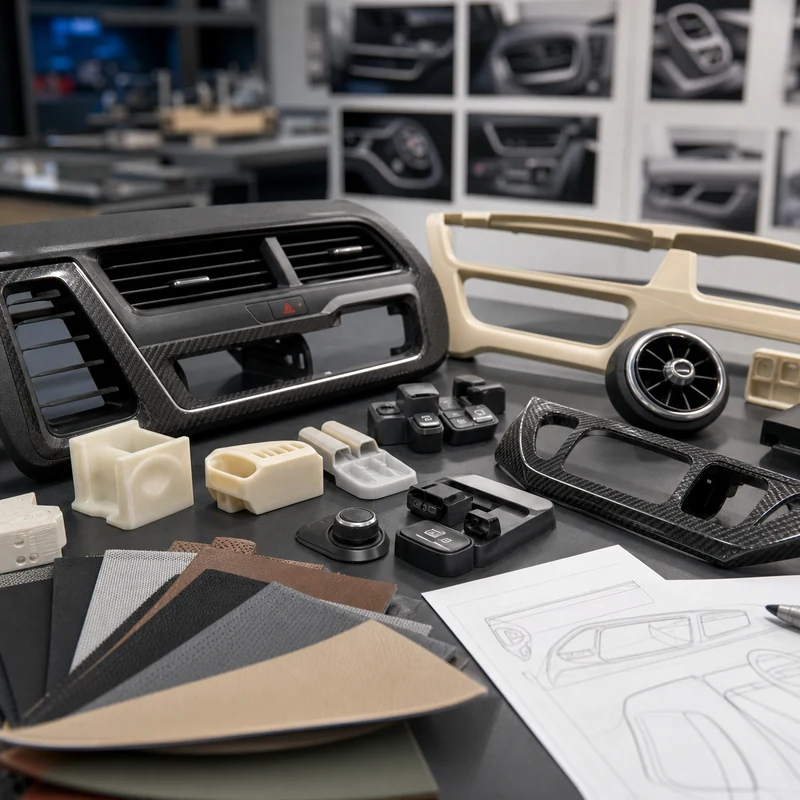
Custom car interior parts include dashboard trim, console panels, knobs, vents, brackets, covers, bezels, switch housings, and personalized cabin components. These parts need more than a nice shape; they must fit accurately, feel right to the user, resist wear, and match the visual style of the vehicle interior.

For prototypes and low-volume customization, CNC machining, 3D printing, vacuum casting, and finishing are often combined. The right process depends on geometry, quantity, material, surface texture, heat exposure, and whether the part is functional, cosmetic, or both.

Common Car Interior Part Processes

Process Best For Notes
CNC machining Trim, bezels, fixtures, aluminum knobs, plastic panels High accuracy and real material properties
3D printing Concept models and ergonomic tests Fast, but surface finish and strength vary
Vacuum casting Small batches with molded appearance Good for soft-touch or cosmetic prototypes
Injection molding High-volume production Higher tooling cost but low unit cost

Material Choices

ABS, PC, nylon, acrylic, aluminum, and soft elastomers are common choices. ABS is economical and easy to finish. PC provides impact resistance. Aluminum is used for premium knobs, handles, decorative trim, and durable functional parts.

  • ABS for general trim and covers
  • PC for impact-resistant transparent or protective parts
  • Nylon for clips, guides, and wear points
  • Aluminum for premium or high-strength features

Design Requirements

Interior parts must fit around existing geometry. Clip positions, screw bosses, tabs, wall thickness, texture direction, and assembly clearance should be checked before production.

Finish and Appearance

Painting, polishing, bead blasting, anodizing, vapor smoothing, and texture matching can change the final look. Cosmetic surfaces should be marked clearly on the drawing.

Design and Sourcing Notes

A good interior part design balances appearance, assembly, hand feel, heat exposure, vibration, and repeatable manufacturing.

  • Keep snap-fit clips realistic for the chosen material.
  • Avoid very thin decorative lips that can warp or break.
  • Confirm UV, heat, and cleaning-chemical exposure.
  • Prototype visible parts before committing to tooling.

Quality Checks That Matter

Check mating features, clip engagement, screw hole position, visible surface defects, color/texture consistency, and assembly fit. Interior parts often fail because of fit and finish, not because of raw strength alone.

Related MTSPi Resources

FAQ

What material is best for car interior trim?

ABS is common for general trim, while PC, nylon, aluminum, and elastomers are used when impact, wear, or premium appearance matters.

Can CNC machining make interior parts?

Yes, especially prototypes, low-volume parts, aluminum trim, and precise plastic components.

What matters most for custom interior parts?

Fit, surface appearance, heat resistance, clip strength, and assembly clearance are usually the key factors.

Categories
Blog CNC Machining Basics

Tack Welding Explained: Purpose, Types, Advantages, and Design Notes

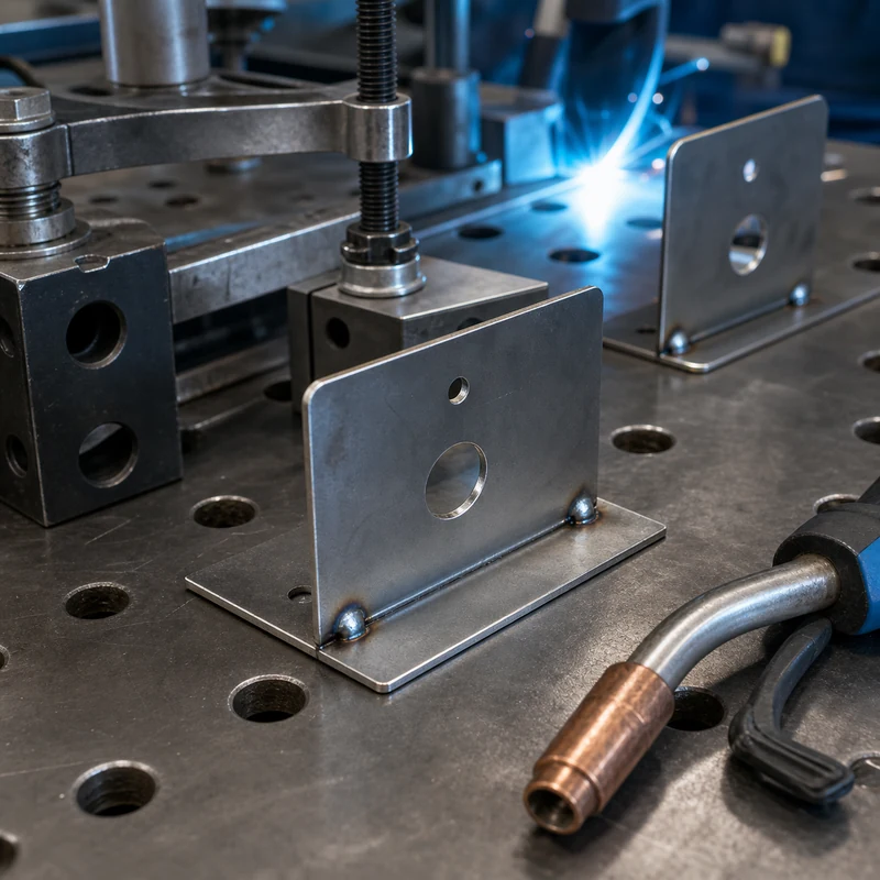
Tack welding is the temporary or semi-permanent weld used to hold parts in position before the final weld is completed. It may look small, but it controls alignment, gap, distortion, and assembly repeatability during sheet metal and welded structure production.

For CNC machined and fabricated assemblies, tack welding is not just a shop-floor shortcut. It is part of process planning. Poor tack weld placement can pull brackets out of position, create stress, or make final welding harder. Good tack welding keeps the part stable while leaving enough access for final welding, grinding, inspection, and finishing.

Quick Comparison of Tack Welding Methods

Tack Weld Type Best Use Main Risk
Small intermittent tacks Thin sheet metal and light brackets Can break if handling is rough
Bridge tacks Maintaining a root gap before final welding Must be removed or fused correctly
Strong temporary tacks Heavy fixtures and structural parts May add distortion if oversized
Corner tacks Boxes, frames, and folded assemblies Can lock in misalignment if sequence is wrong

Why Tack Welding Is Used

Tack welds keep individual pieces from moving while a welder checks fit-up and prepares the final weld sequence. They reduce the need for complex clamps, shorten setup time, and help maintain the intended geometry of brackets, frames, covers, panels, and welded fixtures.

  • Holds parts before final welding
  • Maintains spacing and joint alignment
  • Reduces assembly movement during handling
  • Helps control distortion when used with the right sequence

Where Tack Welding Fits in Fabrication

Tack welding is common in sheet metal enclosures, welded frames, automotive brackets, machinery guards, equipment bases, and prototype metal assemblies. It is especially useful when parts are cut, bent, machined, then welded into a final assembly.

Common Mistakes

The most common problems are oversized tacks, poor cleaning, wrong sequence, bad fit-up, and putting tack welds where final weld access is blocked. A tack weld should support the process, not create a defect that must be repaired later.

Design and Sourcing Notes

Designers should think about tack welding while defining joint access, bend sequence, hole locations, and finishing requirements.

  • Leave enough weld access around corners and flanges.
  • Avoid placing cosmetic surfaces where tack marks will be difficult to remove.
  • Specify critical dimensions after welding if distortion matters.
  • Plan surface treatment after welding and cleanup.

Quality Checks That Matter

Inspection should check alignment, gap, cracks, incomplete fusion, and distortion before final welding proceeds. For precision assemblies, dimensional inspection after welding may be more important than measuring each flat part before welding.

Related MTSPi Resources

FAQ

Is tack welding permanent?

It can become part of the final weld if properly fused, but many tack welds are temporary positioning welds.

Does tack welding cause distortion?

Yes, if tack welds are too large or placed in a poor sequence. Balanced tack placement helps reduce movement.

Should tack welds be inspected?

Yes. Cracked or poorly placed tack welds can affect the final weld and part alignment.

Categories
Blog CNC Materials

Types of Nylon: Grades, Properties, and CNC Machining Selection Guide

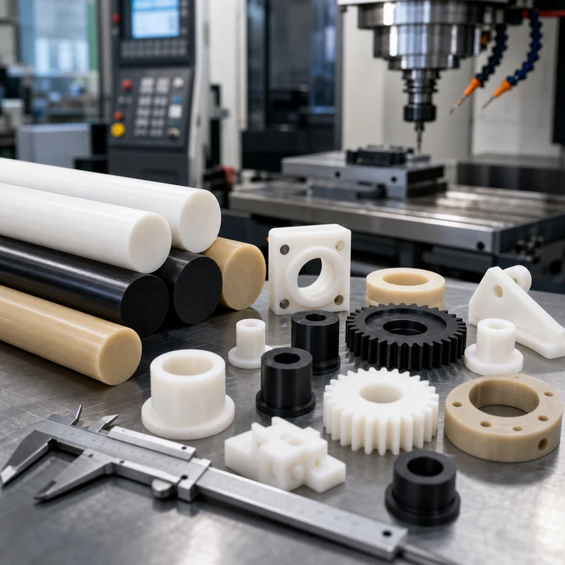
Nylon is one of the most widely used engineering plastics, but the word “nylon” does not describe one single material. PA6, PA66, PA12, PA11, PA6/12, glass-filled nylon, mineral-filled nylon, and impact-modified nylon can behave very differently in machining, assembly, moisture exposure, heat, and long-term wear. Choosing the wrong type can lead to swelling, loose tolerances, tool wear, cracked thin walls, or parts that work in the prototype stage but fail in production.

This guide explains the main types of nylon from a CNC machining and product-design point of view. It is written for engineers, sourcing teams, and product developers who need practical material selection help before ordering machined plastic parts. For project-specific material review, MTSPi can also evaluate drawings through our nylon CNC machining and broader CNC plastic machining capabilities.

Quick Answer: Which Type of Nylon Should You Choose?

Nylon Type Best For Main Strength Main Caution
PA6 / Nylon 6 General machined parts, gears, rollers, wear pads, prototypes Tough, economical, good wear resistance Absorbs moisture and may move dimensionally
PA66 / Nylon 6/6 Higher strength parts, wear components, electrical and mechanical parts Higher stiffness, wear resistance, and heat performance than PA6 Still absorbs moisture; can be harder to machine cleanly
PA6/12 Moisture-sensitive applications, molded parts, cable and fluid-system components Lower moisture absorption than PA6 or PA66 Usually less strong than PA66
PA11 Flexible, impact-resistant, lower-moisture parts, often 3D printed Bio-based source, good low-temperature impact performance Lower heat resistance than some nylon grades
PA12 SLS/MJF printed parts, lightweight housings, ducts, fixtures, flexible functional prototypes Low moisture absorption and good chemical resistance Lower stiffness unless filled
Glass-filled nylon Stiff brackets, structural parts, heat-resistant components Higher stiffness, strength, and thermal stability More abrasive; can wear tools and expose rougher edges
Mineral-filled nylon Dimensionally stable parts, heat-resistant molded components Lower shrinkage and better stability Can be more brittle depending on formulation

What Is Nylon?

Nylon is a family of polyamide materials. The “PA” abbreviation means polyamide, and the number in a grade name describes the chemistry of the polymer chain. That chemistry affects melting point, moisture absorption, stiffness, toughness, fatigue behavior, and chemical resistance. This is why two nylon grades may look similar but behave differently after machining.

Most nylon materials offer good wear resistance, low friction, toughness, and chemical resistance compared with commodity plastics. They are often used for gears, bushings, rollers, guides, electrical insulators, spacers, housings, and mechanical components that need to be lighter than metal. The tradeoff is moisture absorption. Many nylons absorb water from the environment, which can change part dimensions and mechanical properties.

Why Nylon Type Matters for CNC Machining

CNC machining removes material from nylon stock such as sheet, plate, rod, or tube. Nylon machines well compared with many plastics, but it is not as rigid as metal. It can deflect under cutting force, soften if heat builds up, and expand or shrink with moisture and temperature. Grade selection therefore affects more than material strength; it affects how accurately the part can be held after machining.

  • PA6 and PA66 are common for machined mechanical components, but moisture control should be considered.
  • PA12 and PA11 are often more stable in humid applications, especially in additive manufacturing contexts.
  • Filled nylons improve stiffness and heat resistance but can create tool wear and edge-quality challenges.
  • Thin walls, deep slots, small holes, and tight press fits should be reviewed before production.

Nylon 6 (PA6): Tough and Economical, but Moisture Sensitive

PA6 is one of the most common nylon grades for machined plastic parts. It offers a strong balance of toughness, wear resistance, machinability, and cost. It is frequently selected for rollers, gears, wear pads, bushings, guide blocks, spacers, and general mechanical components.

The main caution with PA6 is moisture absorption. In a dry shop environment, a PA6 part may measure correctly after machining, but it can change size after absorbing moisture in service. For loose-clearance parts this may be acceptable. For close-fit holes, sliding features, bearing seats, or assembly-critical dimensions, the design should allow for environmental movement.

Nylon 6/6 (PA66): Stronger, Stiffer, and More Heat Resistant

PA66, also called Nylon 6/6, usually offers higher stiffness, tensile strength, wear resistance, and heat resistance than PA6. This makes it a good candidate for more demanding mechanical parts, especially when a component needs improved load capacity or better dimensional performance under moderate heat.

PA66 is widely used for gears, electrical components, bushings, housings, fastener-related parts, and structural plastic components. For CNC machining, it generally cuts well, but the same moisture warning applies. If a drawing calls for tight tolerance after conditioning or after exposure to humidity, that should be stated clearly.

Nylon 6/12 (PA6/12): Better Moisture Resistance

PA6/12 is often selected when lower moisture absorption is more important than maximum strength. It is common in applications such as tubing, cable protection, fuel-related components, bristles, and molded parts that must remain more stable in humid or fluid-contact environments.

For machined parts, PA6/12 can be useful when PA6 or PA66 swelling is a concern. It may not match the strength of PA66, so the choice should be based on the real service condition: load, humidity, chemical exposure, operating temperature, and assembly clearance.

Nylon 11 (PA11): Flexible, Impact Resistant, and Bio-Based

PA11 is known for toughness, flexibility, low-temperature impact performance, and lower moisture absorption than PA6 and PA66. It is also often discussed because its raw material source can be bio-based. In manufacturing, PA11 appears frequently in 3D printing and flexible functional components rather than as the first default for CNC machining from stock.

Choose PA11 when impact resistance, flexibility, and moisture stability matter more than maximum stiffness. For rigid precision-machined parts, compare it with PA12, Delrin/POM, or reinforced nylon depending on the application.

Nylon 12 (PA12): Stable, Chemical Resistant, and Common in 3D Printing

PA12 is a popular material for SLS and Multi Jet Fusion 3D printed parts, but it is also useful as a reference point when comparing nylon types. It generally absorbs less moisture than PA6 and PA66, offers good chemical resistance, and can produce functional prototypes, ducts, clips, housings, and fixtures.

Unfilled PA12 is not always as stiff as filled nylon or PA66, so designers should check wall thickness and load conditions. Glass-filled or mineral-filled PA12 can improve mechanical and thermal performance, but filled formulations may change surface finish and part toughness.

Filled Nylon: Glass, Mineral, Carbon, and Impact-Modified Grades

Fillers are added to nylon to change its mechanical behavior. Glass-filled nylon is common because it increases stiffness, strength, and heat resistance. Mineral-filled nylon can improve dimensional stability and reduce shrinkage. Impact-modified nylon improves toughness. Carbon-filled nylon can improve stiffness, conductivity, or static-control behavior depending on the formulation.

Filled Nylon Type What It Improves Design / Machining Note
Glass-filled nylon Stiffness, strength, creep resistance, heat performance More abrasive on tools; edges may feel sharper or rougher
Mineral-filled nylon Dimensional stability, lower shrinkage, heat stability May reduce impact strength depending on grade
Impact-modified nylon Toughness and resistance to cracking May reduce stiffness compared with reinforced grades
Carbon-filled nylon Stiffness, wear, or electrical/static behavior Confirm conductivity and surface requirements before selection

Filled nylon is not automatically better. If a part needs snap-fit flexibility, impact toughness, or smooth bearing contact, an unfilled or differently modified grade may perform better. If a part needs stiffness, heat resistance, and low creep, filled nylon may be the better choice.

Nylon vs Delrin, PEEK, and Polycarbonate

Nylon is not always the best plastic. Delrin/POM is often selected when low moisture absorption and dimensional stability are more important than nylon-like toughness. PEEK is far more expensive but performs well under heat, chemicals, and demanding environments. Polycarbonate is selected for impact-resistant transparent parts. Acrylic is selected for optical clarity but is more brittle.

Material Use Instead of Nylon When You Need Related MTSPi Page
Delrin / POM Better dimensional stability, low friction, crisp machining Delrin CNC machining
PEEK High temperature, chemical resistance, medical or aerospace-grade performance PEEK CNC machining
Polycarbonate Impact-resistant transparent parts PC CNC machining
Acrylic Clear cosmetic panels and polished optical surfaces Acrylic CNC machining

Design Tips for CNC Machined Nylon Parts

  • Avoid specifying metal-like tolerances on non-critical nylon features.
  • Use generous radii and avoid sharp internal corners where stress can concentrate.
  • Support thin walls with ribs or additional thickness when possible.
  • Leave realistic clearance for holes, bushings, sliding parts, and moisture exposure.
  • Specify whether final dimensions should be checked dry, conditioned, or after finishing.
  • Plan deburring carefully; nylon can leave stringy burrs around drilled holes and edges.

Surface Finish and Inspection

Nylon parts are usually machined to a functional finish rather than polished like cosmetic metals. Tool sharpness, feed rate, chip evacuation, and heat control all affect the final surface. If a part has sealing areas, sliding contact, or visible surfaces, call those areas out on the drawing. For related finishing options across CNC parts, see surface treatment planning.

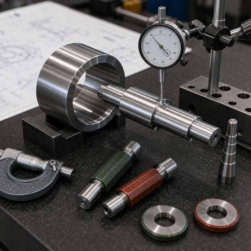
Inspection should match the way the part functions. Simple parts may only need caliper and gauge checks. Precision assemblies may require bore gauges, pin gauges, thread gauges, optical checks, or CMM measurement. For projects with tight tolerances or production documentation, connect the drawing requirements with quality assurance before machining begins.

How MTSPi Helps With Nylon Material Selection

MTSPi supports CNC machining for nylon and other engineering plastics, including prototypes, low-volume production, and repeat orders. We can review material options, machining strategy, wall thickness, hole design, thread feasibility, finish expectations, and inspection requirements before quoting. If the nylon type is not fixed yet, we can compare PA6, PA66, PA12, Delrin, PEEK, PC, and other plastics against the actual application.

To move forward, send your 3D model, 2D drawing, material preference, annual or batch quantity, target tolerance, and operating environment through our contact page. You can also browse the broader CNC machining materials library for other material choices.

FAQ

What is the strongest type of nylon?

For many machined-part applications, PA66 and glass-filled nylon are stronger and stiffer than general PA6. However, the best choice depends on load, moisture, temperature, impact, and whether the part needs flexibility.

Which nylon absorbs the least moisture?

PA11 and PA12 generally absorb less moisture than PA6 and PA66. PA6/12 is also selected when better moisture resistance is needed compared with PA6 or PA66.

Is nylon good for CNC machining?

Yes. Nylon is commonly CNC machined for gears, bushings, rollers, spacers, guides, and wear parts. The main concerns are moisture movement, burr control, heat buildup, and realistic tolerances.

Is glass-filled nylon better than standard nylon?

Glass-filled nylon is better when stiffness, strength, creep resistance, and heat performance are priorities. It is not always better for impact, flexibility, tool wear, edge finish, or sliding contact.

What is the best nylon for gears and bushings?

PA6, PA66, and some filled nylon grades can work for gears and bushings. The final choice depends on load, speed, lubrication, temperature, moisture, and required dimensional stability.

Can MTSPi machine nylon prototypes and production parts?

Yes. MTSPi can machine nylon parts from drawings for prototypes, low-volume production, and batch supply, with material and inspection planning matched to the application.


Categories
Blog Quality & Tolerances

Engineering Tolerances Explained: Meaning, Types, Fits, and Design Use

Engineering tolerance defines how much a manufactured dimension is allowed to vary from the nominal design value. No machining process creates a perfect mathematical part, so tolerances tell the manufacturer what variation is acceptable and what must be rejected.

For CNC parts, good tolerancing is not about making every dimension extremely tight. It is about controlling the features that affect fit, motion, sealing, strength, or alignment while keeping non-critical dimensions practical. This balance improves quality and keeps machining cost under control.

Basic Tolerance Terms

Term Meaning
Nominal dimension The target size shown on the drawing
Upper limit The largest acceptable size
Lower limit The smallest acceptable size
Tolerance zone The total allowed variation between limits
Fit How two mating parts interact after manufacturing
Datum A reference feature used for measurement or assembly

Types of Engineering Tolerances

Dimensional tolerances control size, such as length, width, diameter, or depth. Geometric tolerances, often shown through GD&T, control shape, orientation, position, and runout. General tolerances apply when individual dimensions are not specifically called out.

  • Bilateral tolerance allows variation in both directions, such as +/-0.05 mm.
  • Unilateral tolerance allows variation in only one direction, such as +0.02/-0.00 mm.
  • Limit dimensions show the upper and lower values directly.
  • GD&T controls relationships such as flatness, parallelism, profile, true position, and runout.

Fits Between Mating Parts

Fit Type How It Behaves Example
Clearance fit There is always space between mating parts Shaft rotating inside a bushing
Transition fit May have slight clearance or slight interference Accurate locating dowels
Interference fit Parts press together with force Pressed bearing or permanent sleeve

Using ISO 2768 and General Tolerances

Many drawings use a general tolerance standard such as ISO 2768 for dimensions that do not require special control. This keeps drawings readable and avoids unnecessary tight callouts. Critical features should still have specific tolerances or GD&T notes when function demands it.

How to Choose Practical Tolerances

  • Start with the function of the feature, not the machine capability.
  • Tighten only dimensions that affect assembly, motion, sealing, or performance.
  • Consider material movement, heat treatment, plating, anodizing, and other finishing steps.
  • Discuss inspection method for tight or complex tolerances before production.
  • Use datum structures that reflect how the part actually assembles.

If coating thickness matters, coordinate tolerance planning with the surface treatment process. If complex GD&T is involved, confirm that the quality team can measure the feature reliably.

Tolerance and Cost

Tighter tolerance usually increases cost because it may require slower machining, special tooling, more stable fixtures, extra inspection, or secondary finishing. A realistic tolerance strategy helps suppliers quote accurately and reduces back-and-forth during manufacturing review.

Related MTSPi Resources

FAQ

Should every dimension have a tight tolerance?

No. Only functional or assembly-critical features should be tightly controlled.

What is GD&T used for?

GD&T controls geometry and relationships between features, such as position, flatness, parallelism, and runout.

Can surface finishing change tolerances?

Yes. Plating, anodizing, coating, and heat treatment can change dimensions or part behavior, so they should be considered early.

Categories
Blog CNC Milling & Turning

CNC Lathe Guide: Operation, Types, Tools, and Shop Considerations

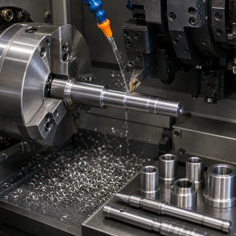
A CNC lathe rotates a workpiece while cutting tools shape the outside diameter, inside diameter, end face, grooves, threads, and other turned features. The controller follows programmed toolpaths, which makes CNC lathes effective for repeatable shafts, bushings, pins, sleeves, fittings, and cylindrical components.

When a part is mostly round, CNC turning is often more efficient than milling. When the same part also needs flats, slots, cross holes, or off-center features, live tooling or mill-turn machining may reduce secondary setups.

How a CNC Lathe Works

  • The chuck or collet holds the raw stock.
  • The spindle rotates the workpiece at a programmed speed.
  • Tools mounted in a turret move along the X and Z axes.
  • Optional Y-axis, C-axis, live tooling, and sub-spindles add more capability.
  • After machining, the part is inspected against the drawing.

Common Lathe Operations

Operation What It Creates
Facing Flat end surfaces
OD turning Outside diameters and shoulders
Boring Accurate internal diameters
Drilling Centerline holes
Grooving O-ring seats, relief grooves, snap-ring grooves
Threading External or internal threads
Parting Cuts the finished part from bar stock

Types of CNC Lathes

A simple two-axis lathe handles many round parts. A turning center with live tooling can drill or mill features without removing the workpiece. Swiss-type lathes are excellent for tiny slender parts. Vertical lathes may be selected for large heavy workpieces that are easier to support upright.

Machine Type Best Use
2-axis CNC lathe Simple shafts, spacers, bushings, and pins
Turning center with live tooling Turned parts with milled flats or radial holes
Swiss-type lathe Small high-precision bar-fed parts
Mill-turn center Complex parts requiring both turning and milling
Vertical lathe Large discs, rings, and heavy rotational parts

Tooling and Accuracy Factors

Insert grade, tool nose radius, holder rigidity, coolant, spindle condition, and workholding all influence finish and tolerance. For high-precision projects, pair the turning plan with documented inspection. Critical diameters, threads, bearing fits, and concentric features should be measured with appropriate gauges or CMM methods.

Choosing a Lathe Shop

A good lathe shop should understand both production efficiency and design intent. Send 3D models, 2D drawings, material requirements, finish notes, quantity, and inspection expectations. The earlier these details are available, the easier it is to avoid unnecessary cost.

Related MTSPi Resources

FAQ

What parts are best for CNC lathes?

Round or cylindrical parts such as shafts, bushings, pins, sleeves, spacers, threaded fittings, and valve components.

Can a lathe make square features?

A basic lathe cannot, but a turning center with live tooling or a mill-turn machine can add flats, slots, and off-center holes.

What affects CNC lathe cost?

Material, tolerance, geometry, setup time, tooling, inspection, finishing, and quantity all affect cost.

Categories
Blog CNC Machining Basics

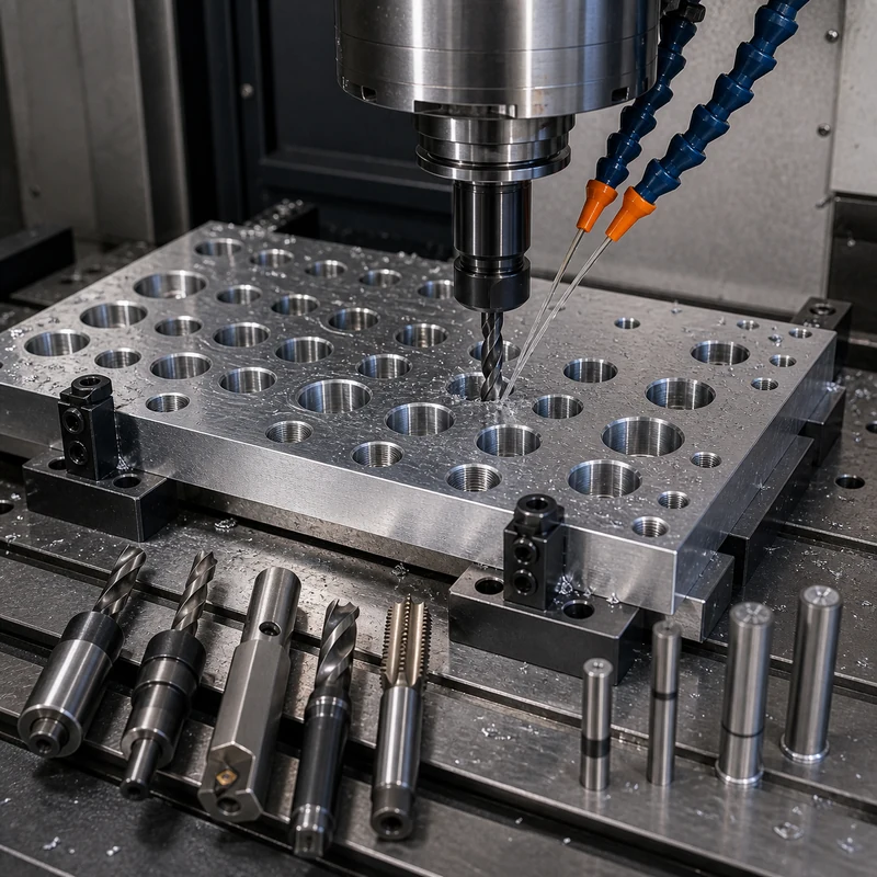
Hole Machining in CNC: Drilling, Boring, Reaming, Tapping, and Design Rules

Quick answer: Hole machining is the CNC process of creating or finishing holes using drilling, boring, reaming, tapping, countersinking, counterboring, or thread milling. The right method depends on hole size, depth, tolerance, surface finish, thread requirement, and inspection needs.

Why Hole Machining Matters

Holes often control how a part assembles. They may locate dowel pins, accept screws, support bearings, pass fluid, reduce weight, or align mating parts. Small errors in hole position, diameter, depth, or thread fit can cause major assembly problems.

Common CNC Hole Machining Methods

Method Purpose Best use
Drilling Creates a basic round hole Clearance holes, pilot holes, general features
Boring Improves or enlarges an existing hole Accurate diameters and alignment-critical bores
Reaming Finishes a hole to closer size and smoother surface Dowel holes, bearing fits, precision diameters
Tapping Cuts internal threads Screw assembly and fastener holes
Thread milling Mills internal or external threads Large threads, hard materials, blind holes, flexible thread control
Countersinking / counterboring Creates screw head seating geometry Flush screws, socket head clearance, assembly hardware

Drilling vs Boring vs Reaming

Drilling is usually the first operation because it creates the hole. Boring improves hole location, straightness, or diameter after drilling. Reaming is used when the hole needs a more accurate final size and better finish than drilling alone can provide.

Design Rules for Better Holes

  • Avoid very deep holes unless they are truly required.
  • Keep hole diameters standard where possible.
  • Leave enough edge distance around holes.
  • Specify whether threads are blind or through.
  • Use realistic tolerances for non-critical clearance holes.
  • Define datum references for hole position when assembly matters.

Hole Tolerances and Inspection

Hole inspection may use pin gauges, bore gauges, CMM inspection, thread gauges, depth gauges, or optical tools. For critical hole patterns, connect the drawing to a clear inspection method before machining.

Material Effects

Aluminum is generally easy to drill and tap. Stainless steel can work-harden and needs suitable tools. Brass cuts cleanly but may grab with the wrong drill geometry. Plastics may require sharp tools and heat control. Material choice should be reviewed through the CNC material guide.

Related CNC Processes

Hole machining appears in both CNC milling and CNC turning. Milled parts often need bolt patterns, dowel holes, and tapped holes. Turned parts often need center holes, bores, cross holes, threads, and counterbores.

FAQ

What is hole machining?

Hole machining is the process of creating or finishing holes with drilling, boring, reaming, tapping, or related operations.

Is drilling enough for precision holes?

Not always. Precision holes may need boring or reaming after drilling.

What is the best method for threaded holes?

Tapping is common for standard threads, while thread milling is useful for larger threads, hard materials, and blind holes.

How do I reduce hole machining cost?

Use standard sizes, avoid unnecessary tight tolerances, limit deep holes, and provide clear thread and depth notes.

Need help choosing a machining route?

Send MTSPi your drawing, material, quantity, finish, and inspection requirements. We will review the part for manufacturability before quoting.

Contact MTSPi for a CNC machining quote

Practical Buyer Notes

Hole machining deserves depth because holes are often the most important assembly features on a part. A simple drilled hole, reamed dowel hole, tapped blind hole, bearing bore, and counterbore all require different planning.

The page should make it clear that drilling is only one hole-making method. Accuracy, surface finish, position, roundness, thread fit, and depth may require boring, reaming, tapping, thread milling, or CMM inspection.

How to Evaluate This Topic on a Real Drawing

Decision point Recommended approach Why it matters
Hole function Classify holes as clearance, threaded, dowel, bearing, fluid, or weight-reduction Function decides tolerance and process
Machining method Use drilling, boring, reaming, tapping, or thread milling as needed Different methods create different accuracy levels
Depth and access Review deep holes, blind holes, and tool clearance Avoids broken tools and poor finish
Inspection Use gauges, CMM, or thread checks for critical holes Prevents assembly failures

Common Mistakes to Avoid

  • Expecting drilled holes to meet precision bore requirements.
  • Leaving thread depth or blind-hole bottom clearance undefined.
  • Putting holes too close to edges, bends, or thin walls.
  • Not defining position tolerance for hole patterns that control assembly.

Recommended MTSPi Review Workflow

MTSPi should review hole features separately from general part geometry. Hole diameter, depth, position, thread, finish, and inspection method often decide the correct machining route.

  1. Confirm the part function, operating environment, and assembly risk.
  2. Review material, process, tolerance, surface finish, and inspection requirements together.
  3. Separate critical features from general dimensions so cost is not wasted on non-functional details.
  4. Use related resources such as CNC materials, surface treatment, and quality assurance to complete the specification.
  5. Send the final drawing package to MTSPi for quote review before production.

What to Send for a Faster Quote

Send drawings with hole callouts, tolerances, thread standards, depth notes, datum references, and mating hardware information where possible.

  • 3D CAD file and 2D drawing with revision number.
  • Material grade or acceptable alternatives.
  • Quantity, delivery target, and whether samples are required first.
  • Critical dimensions, thread callouts, finish notes, and inspection requirements.
  • Application notes when the part is used in heat, moisture, wear, vibration, or visible assemblies.

Example: Choosing the Right Hole Process

A simple bolt clearance hole may only need drilling and deburring. A dowel pin hole may need drilling, reaming, and position inspection. A bearing bore may need boring, controlled surface finish, and diameter verification. A threaded blind hole may need drilling, tapping or thread milling, depth control, and a go/no-go gauge check.

These examples show why hole machining should be specified by function. If a drawing treats every hole the same way, the supplier may over-machine simple holes or under-control critical ones.

Conclusion

Hole machining looks simple, but holes often decide whether a part assembles correctly. Choosing the right method and defining tolerances, threads, and inspection requirements clearly can prevent delays and reduce CNC machining cost.

Categories
Blog CNC Machining Basics

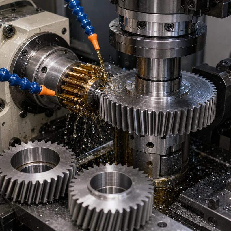
Gear Cutting Guide: Processes, Tools, and Manufacturing Choices

Gear cutting is the manufacturing process used to form teeth on gears, splines, sprockets, and related power-transmission parts. The process must control tooth profile, pitch, concentricity, surface finish, and material condition because small errors can lead to noise, vibration, heat, and premature wear.

Depending on geometry and quantity, gears may be made with dedicated gear equipment or with flexible CNC machining methods. The best route depends on gear type, accuracy class, batch size, material, and whether heat treatment or finishing is required.

Common Gear Cutting Methods

Method How It Works Best Fit
Hobbing A rotating hob progressively generates teeth Spur and helical gears in production
Shaping A reciprocating cutter forms teeth Internal gears and shoulders near obstructions
Gear milling A form cutter or CNC tool machines each tooth space Prototypes, low volume, large gears
Broaching A broach cuts internal profiles in one pass Internal splines and high-volume features
Grinding Abrasive wheel finishes hardened gear teeth High accuracy and improved surface finish

Important Gear Design Factors

  • Module or diametral pitch defines tooth size.
  • Pressure angle affects strength and mesh behavior.
  • Face width influences load capacity and stiffness.
  • Material and heat treatment determine wear resistance.
  • Runout and concentricity affect smooth rotation.

CNC Milling for Gear Prototypes

For prototypes and low-volume gears, CNC milling can be practical because it avoids special tooling and allows fast geometry changes. It is not always the fastest method for high-volume production, but it works well when the design is still evolving or the gear is part of a larger machined assembly. MTSPi can review whether milling-based production is suitable for your geometry.

Material Choices

Steel alloys are common for high-load gears because they can be hardened. Brass and bronze are used when low friction or corrosion resistance is needed. Aluminum may fit lightweight, low-load applications. Engineering plastics can reduce noise and weight, but require careful attention to temperature and wear.

Inspection for Gear Quality

Gear inspection may include tooth thickness, pitch error, runout, profile, surface finish, and hardness. For assemblies that must run quietly, measurement should go beyond simple outside diameter checks. Connect the inspection plan with the quality requirements before production.

Related MTSPi Resources

FAQ

What is the difference between gear hobbing and gear milling?

Hobbing generates teeth continuously with a hob, while milling often cuts tooth spaces one at a time or with programmed toolpaths.

Can CNC machines make gears?

Yes, especially prototypes, custom gears, and low-volume parts. Dedicated gear equipment may be better for large quantities.

Do gears need heat treatment?

Many metal gears do, especially when load and wear resistance are important.

Categories
Blog CNC Materials

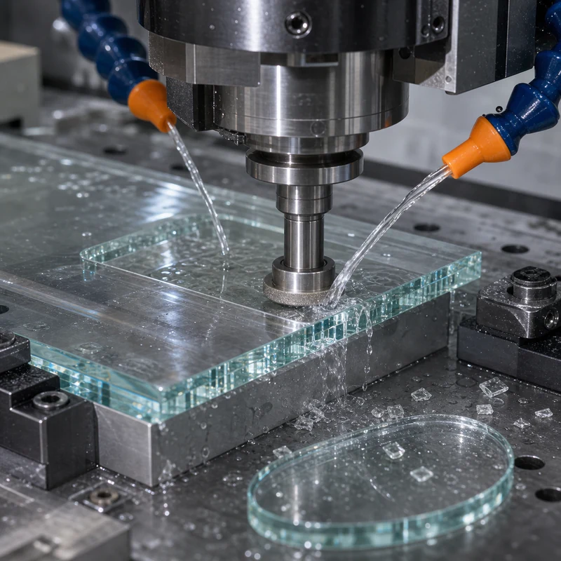
Glass CNC Machining: Cutting Methods, Challenges, and Design Tips

Glass CNC machining is the controlled cutting, drilling, grinding, or shaping of glass with computer-controlled equipment. Unlike aluminum or steel, glass is brittle and can crack if the tool, coolant, speed, fixture, or edge design is wrong. That makes process planning especially important.

Glass components appear in optics, displays, laboratory equipment, electronics, sensors, and decorative industrial products. When a project includes both glass and machined metal parts, MTSPi can help coordinate CNC machining services and assembly-oriented design feedback.

What Makes Glass Different From Metal

Metal usually deforms before it breaks; glass does not. Cutting forces can create microcracks that grow later during handling or assembly. Heat can also stress the material. For this reason, glass machining normally uses diamond tooling, controlled feeds, steady coolant, and careful support.

  • Avoid sharp internal corners where cracks can start.
  • Use generous edge radii or chamfers when possible.
  • Keep thin walls and narrow slots realistic for the glass thickness.
  • Specify edge finish requirements if the part will be visible or sealed.

Common Glass CNC Operations

Operation Purpose Key Concern
Cutting and profiling Create outside shapes or panels Edge chipping and dimensional control
Drilling Create mounting or fluid holes Breakout on exit side
Grinding Improve edge quality and size Heat, feed rate, and wheel condition
Pocketing or recessing Add shallow features Crack prevention and support
Polishing Improve optical or cosmetic finish Time and cost increase

Design Tips for Better Results

Designers should treat glass as a precision brittle material, not just a transparent sheet. Keep hole spacing away from edges, choose thickness that can survive handling, and avoid combining deep slots with sharp corners. If a part will be clamped, gasketed, or bonded, identify the contact zones on the drawing.

Material and Process Considerations

Different glass types behave differently. Soda-lime glass, borosilicate glass, quartz, and optical glass each require different tooling and parameters. When glass parts mate with metal housings, check tolerance stack-up carefully. Metal features may be produced by milling or turning, while glass may need looser allowances to prevent stress during assembly.

Inspection and Handling

Glass parts should be inspected for chips, cracks, edge quality, hole position, and thickness. Clean handling matters because small edge damage can turn into a later fracture. Packaging should prevent part-to-part contact, especially for polished or coated surfaces.

Related MTSPi Resources

FAQ

Can glass be CNC machined accurately?

Yes, but achievable tolerance depends on glass type, thickness, feature geometry, and edge finish requirements.

Why does glass chip during machining?

Chipping usually comes from brittle fracture, excessive force, poor support, or unsuitable tooling.

Can threaded holes be machined in glass?

It is generally risky. Inserts, bonded hardware, or through holes with fasteners are often safer design choices.

Categories
Blog Quality & Tolerances

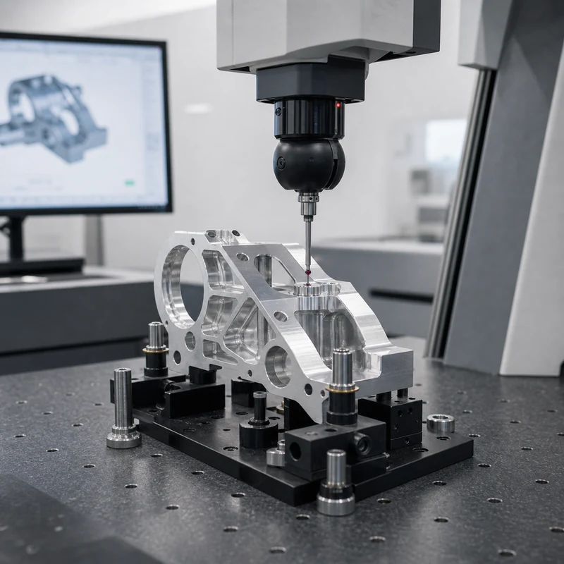
CMM Inspection Explained: How Coordinate Measuring Machines Check Parts

CMM inspection uses a coordinate measuring machine to capture accurate points on a part and compare them with a drawing or CAD model. It is one of the most important measurement methods for precision machined components, especially when parts include GD&T callouts, true position, flatness, profile, or complex relationships between features.

For high-value parts, CMM results can support first article inspection, production approval, and ongoing quality control. MTSPi includes CMM and other inspection methods as part of its quality assurance workflow when the drawing requires documented measurement.

How CMM Inspection Works

A CMM records coordinates in X, Y, and Z. A probe touches or scans the workpiece, and software uses the measured points to calculate dimensions, feature locations, and geometric tolerances. The part is usually held on a granite table with fixtures that keep it stable during inspection.

  • The operator imports the CAD model or enters drawing dimensions.
  • The part is aligned to a datum structure.
  • The probe measures selected features.
  • Software compares actual data with nominal values and tolerances.
  • A report shows pass/fail results and measured deviations.

Features Commonly Checked by CMM

Feature What CMM Can Confirm
Hole patterns True position, diameter, spacing, and depth references
Flat surfaces Flatness, parallelism, and datum relationships
Profiles and contours Surface profile against CAD geometry
Milled pockets Width, depth, corner location, and wall position
Turned parts Concentricity, runout, diameter, and length relationships

CMM vs Other Inspection Tools

Tool Best For Limitation
Caliper Quick general checks Limited accuracy and operator-dependent
Micrometer Accurate outside or inside dimensions Not ideal for complex feature relationships
CMM GD&T and multi-feature geometry Requires programming and setup time
Optical system Small features and non-contact checks May struggle with hidden surfaces

When to Request a CMM Report

Request CMM inspection when a part has tight tolerances, important assembly alignment, safety-critical function, or customer documentation requirements. If the part includes machining plus coating, it is useful to decide whether inspection should happen before finishing, after finishing, or both. This is especially important for close-fit holes, bearing seats, and sealing surfaces connected to surface treatment.

Related MTSPi Resources

FAQ

Is CMM inspection required for every part?

No. It is most useful for complex geometry, tight tolerance features, GD&T, and documented inspection requirements.

Can a CMM inspect plastic parts?

Yes, but fixturing and probe force should be chosen carefully because plastics may flex.

What is included in a CMM report?

Reports typically include measured dimensions, nominal values, tolerance limits, deviations, and pass/fail status.

Categories
Blog Quality & Tolerances

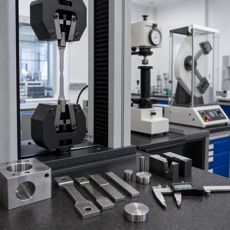
Mechanical Testing Guide: Methods, Benefits, and Manufacturing Use

Mechanical testing measures how a material or finished part behaves under force, load, impact, bending, wear, or repeated stress. For machined components, testing helps confirm that the selected material and manufacturing route can meet real service conditions, not just drawing dimensions.

In a complete manufacturing plan, mechanical testing works alongside dimensional inspection, material certification, and quality assurance controls. It is especially useful for load-bearing parts, safety-related assemblies, and components that operate under heat, vibration, or fatigue.

Why Mechanical Testing Matters

  • It verifies strength, ductility, hardness, and other performance properties.
  • It helps compare candidate materials before production.
  • It supports failure analysis when parts crack, deform, or wear too quickly.
  • It provides objective data for quality documents and customer approval.

Common Mechanical Testing Methods

Test Method What It Measures Typical Use
Tensile testing Strength, yield point, elongation Material qualification and comparison
Hardness testing Resistance to indentation Heat treatment checks and wear expectations
Impact testing Energy absorbed during fracture Low-temperature or shock-load applications
Fatigue testing Life under repeated loading Rotating, vibrating, or cyclic-load components
Compression testing Behavior under crushing force Spacers, blocks, structural parts
Bend testing Ductility and crack resistance Sheet, welds, and formed parts

Testing Before and After Machining

Material testing may happen before machining to confirm that incoming stock meets specification. Finished-part testing may happen after machining, heat treatment, coating, or assembly. For example, a stainless shaft might need hardness verification after heat treatment, while an aluminum bracket may need dimensional checks after surface finishing to confirm coating buildup has not affected assembly features.

How to Choose the Right Test

The correct test depends on how the component will fail if something goes wrong. A cosmetic cover does not need the same test plan as a load-bearing aerospace bracket. Engineers should connect each test to a functional requirement, such as clamp load, wear life, fracture resistance, or dimensional stability.

  • Define the service environment: temperature, load, chemicals, and vibration.
  • Identify critical material properties from the design.
  • Choose a recognized test method when documentation is required.
  • Plan sample size and acceptance criteria before production starts.

Mechanical Testing and CNC Part Quality

CNC machining controls shape, tolerance, and finish, but it does not automatically guarantee material performance. When both geometry and material behavior matter, combine machining with certificates, inspection records, and test results. MTSPi can help align machining, inspection, and documentation for production projects.

Related MTSPi Resources

FAQ

Does every CNC part need mechanical testing?

No. Testing should match the risk, function, material, and customer requirements of the part.

Is hardness testing destructive?

Some hardness tests leave small marks, while others are more suitable for finished surfaces. The method should be chosen carefully.

Can mechanical testing replace dimensional inspection?

No. It answers different questions. Mechanical testing checks performance properties, while dimensional inspection checks geometry.

Request A Quote

We'll Send You Back with Price Immediately!

DEC 1-31

XMAS SPECEIL

Up to

40% off

Mechanical Testing Guide: Methods, Benefits, and Manufacturing Use

We'll Send You Back with Price Immediately!