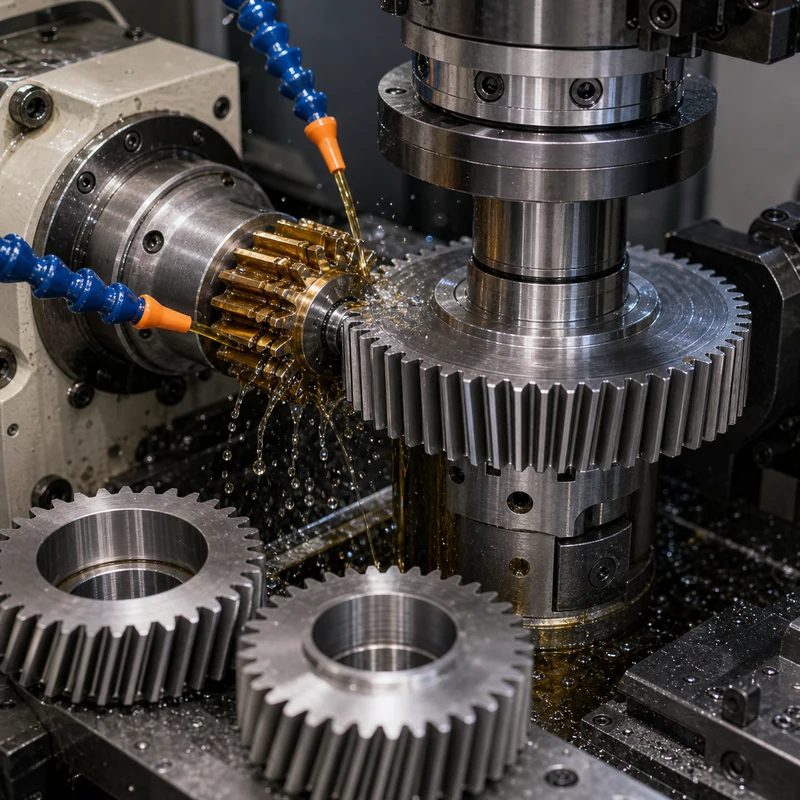
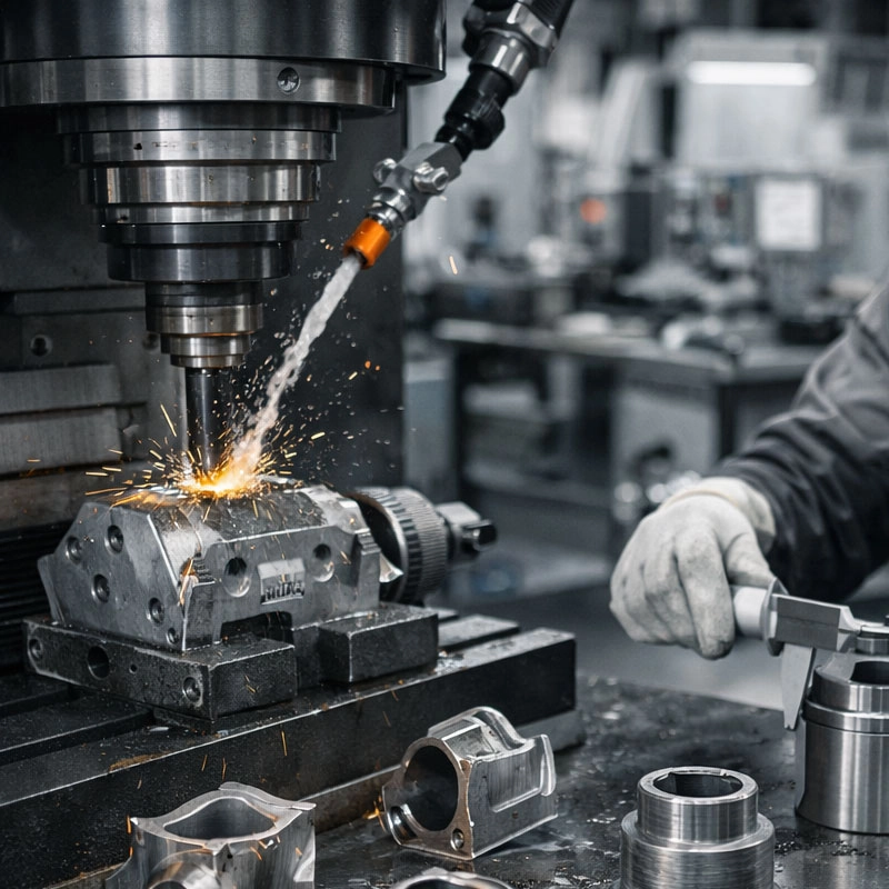
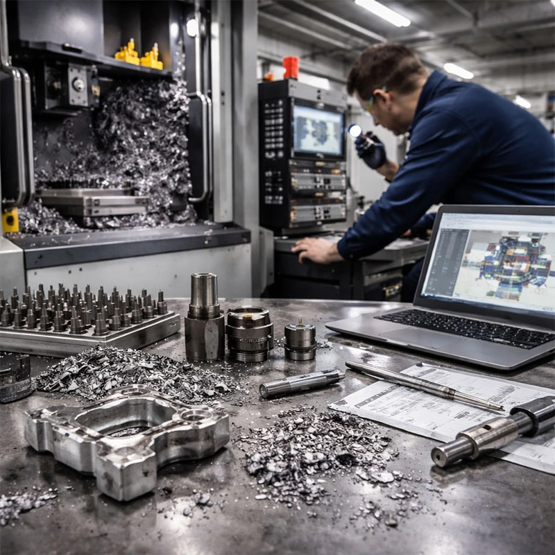
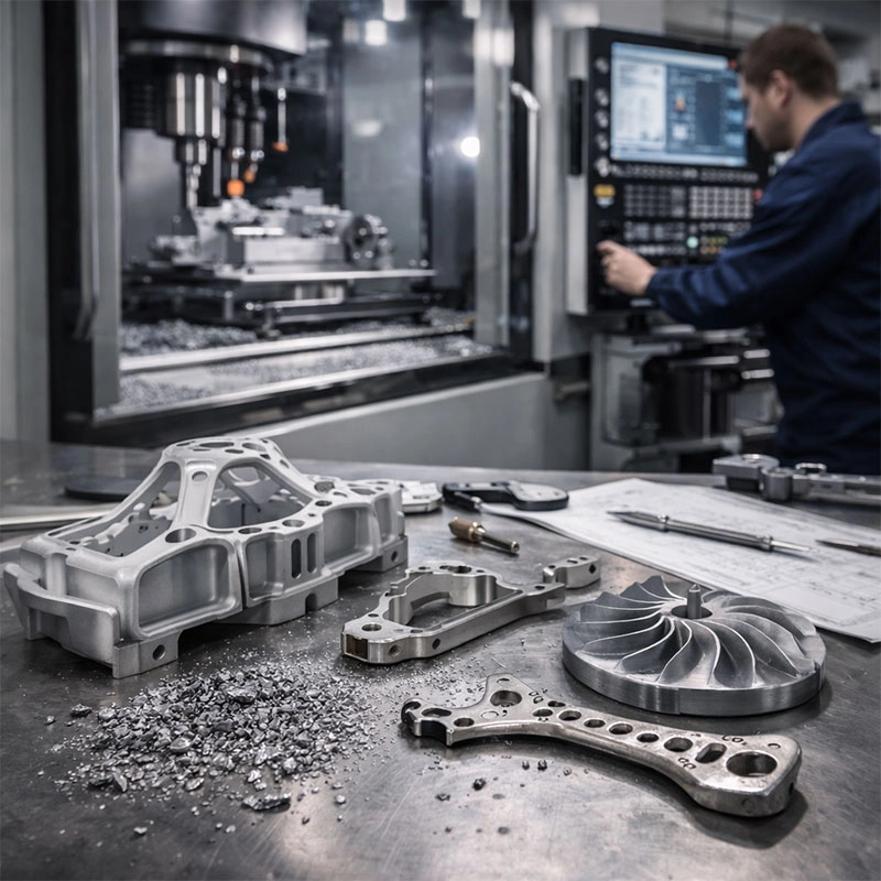
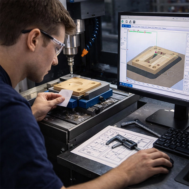
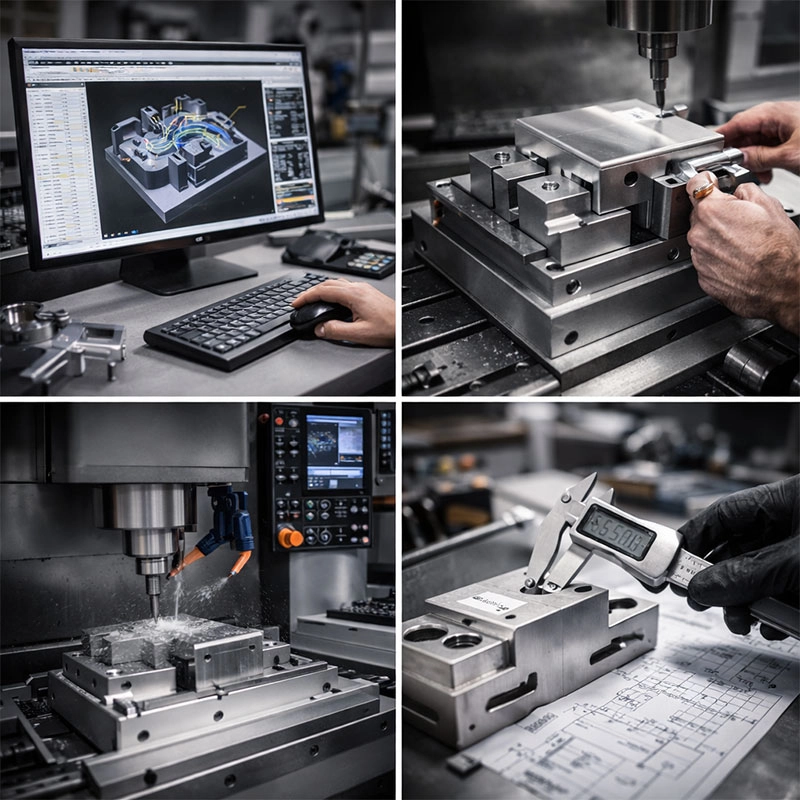
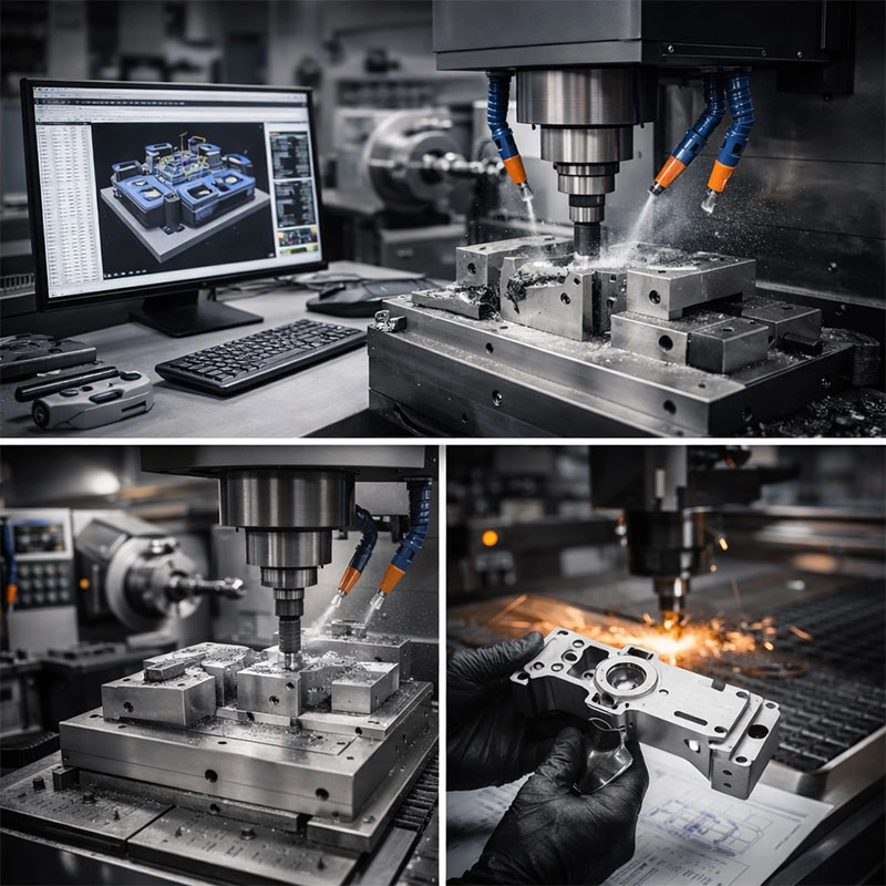
Gear cutting is the manufacturing process used to form teeth on gears, splines, sprockets, and related power-transmission parts. The process must control tooth profile, pitch, concentricity, surface finish, and material condition because small errors can lead to noise, vibration, heat, and premature wear.
Depending on geometry and quantity, gears may be made with dedicated gear equipment or with flexible CNC machining methods. The best route depends on gear type, accuracy class, batch size, material, and whether heat treatment or finishing is required.
Common Gear Cutting Methods
Method
How It Works
Best Fit
Hobbing
A rotating hob progressively generates teeth
Spur and helical gears in production
Shaping
A reciprocating cutter forms teeth
Internal gears and shoulders near obstructions
Gear milling
A form cutter or CNC tool machines each tooth space
Prototypes, low volume, large gears
Broaching
A broach cuts internal profiles in one pass
Internal splines and high-volume features
Grinding
Abrasive wheel finishes hardened gear teeth
High accuracy and improved surface finish
Important Gear Design Factors
Module or diametral pitch defines tooth size.
Pressure angle affects strength and mesh behavior.
Face width influences load capacity and stiffness.
Material and heat treatment determine wear resistance.
Runout and concentricity affect smooth rotation.
CNC Milling for Gear Prototypes
For prototypes and low-volume gears, CNC milling can be practical because it avoids special tooling and allows fast geometry changes. It is not always the fastest method for high-volume production, but it works well when the design is still evolving or the gear is part of a larger machined assembly. MTSPi can review whether milling-based production is suitable for your geometry.
Material Choices
Steel alloys are common for high-load gears because they can be hardened. Brass and bronze are used when low friction or corrosion resistance is needed. Aluminum may fit lightweight, low-load applications. Engineering plastics can reduce noise and weight, but require careful attention to temperature and wear.
Inspection for Gear Quality
Gear inspection may include tooth thickness, pitch error, runout, profile, surface finish, and hardness. For assemblies that must run quietly, measurement should go beyond simple outside diameter checks. Connect the inspection plan with the quality requirements before production.
Quick answer: CNC machining tolerances define how much a finished dimension may vary from the drawing value. Standard tolerances are easier and cheaper to produce, while tight tolerances require better process control, stable material, rigid workholding, suitable tooling, slower machining, and more inspection. The best drawings apply tight tolerances only to features that affect fit, function, sealing, motion, or assembly.
What Are CNC Machining Tolerances?
A tolerance is the acceptable variation around a nominal dimension. If a drawing says 20.00 ±0.05 mm, the feature can pass inspection between 19.95 mm and 20.05 mm. No machining process makes every dimension exactly perfect, so tolerances tell the manufacturer what variation is acceptable.
CNC machining can be very accurate, but not every feature needs the same accuracy. A clearance pocket, cosmetic chamfer, threaded mounting hole, bearing bore, and dowel pin hole all serve different functions. Tolerances should match those functions.
Tight tolerances increase cost because they reduce the room for normal process variation. The machinist may need more careful setup, additional finishing passes, better fixtures, slower cutting, sharper tools, more stable material, in-process checks, and final inspection. If the part moves after material removal or finishing, the process may need stress relief or a different sequence.
Cost often rises fastest when every dimension is marked tight even though only a few features are functional. A good tolerance strategy protects important interfaces while allowing normal manufacturing variation elsewhere.
Factors That Affect CNC Tolerance Capability
Material: Aluminum is generally easier to hold than flexible plastics or difficult heat-resistant alloys.
Geometry: Thin walls, deep pockets, long shafts, and slender features can move during machining.
Setup count: More setups can introduce alignment variation between features.
Tooling: Tool wear, deflection, diameter, coating, and runout affect accuracy.
Workholding: Weak clamping or distorted parts can ruin tolerance even with a good machine.
Heat: Cutting heat and thermal expansion can change measurements.
Finishing: Anodizing, plating, coating, blasting, and polishing may change surfaces or dimensions.
Inspection method: A tolerance is only useful if it can be measured reliably.
ISO 2768 and General Drawing Tolerances
Many mechanical drawings use a general tolerance standard such as ISO 2768 for dimensions that do not have individual tolerances. ISO 2768 tolerance classes help avoid writing a tolerance next to every dimension. However, buyers should still mark critical dimensions separately when the default class is not enough.
For international sourcing, do not assume every shop uses the same default tolerance. Put the standard on the drawing, confirm the class, and identify functional features. If a part will be inspected against GD&T, define datums clearly.
Typical CNC Tolerance Decisions
Feature
Common concern
Practical recommendation
Clearance hole
Bolt or screw must pass through
Use practical clearance unless position is critical
Dowel pin hole
Accurate location and fit
Use reaming, positional tolerance, and gauge/CMM inspection
Bearing bore
Diameter, roundness, finish
Define fit, surface finish, and inspection method
Cosmetic surface
Appearance rather than fit
Use finish notes instead of unnecessary dimensional tolerance
Threaded hole
Fastener engagement and fit
Define thread callout, depth, class, and gauge requirement
Thin wall
Deflection and movement
Avoid tight tolerance unless the wall is supported and measurable
Tolerance and Material Selection
Different materials respond differently to machining. Aluminum is stable and cost-effective for many precision parts. Stainless steel is strong but can work-harden and generate heat. Brass machines cleanly. Titanium and nickel alloys need more careful cutting strategies. Plastics can absorb moisture, flex under clamping, and move after machining. Before locking tolerances, compare options in the CNC materials guide.
Tolerance and Surface Finishing
Finishing can change dimensions and surface texture. Anodizing adds or converts surface layers on aluminum. Plating adds thickness. Powder coating is much thicker than most machined tolerance bands. Polishing can remove material. If a feature is tolerance-critical, state whether the tolerance applies before or after finishing and whether masking is required. See surface treatment options when appearance or corrosion resistance matters.
Inspection Methods for Toleranced Parts
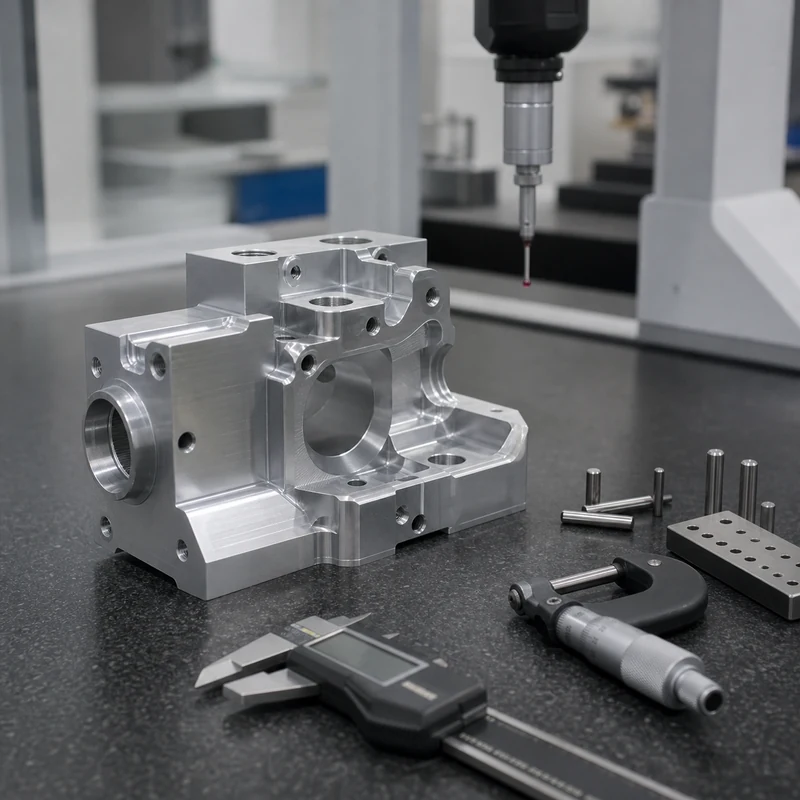
Simple dimensions may be checked with calipers or micrometers. Precision holes may need pin gauges, plug gauges, bore gauges, or air gauges. GD&T features may require CMM inspection. Threads usually need go/no-go gauges. Surface roughness needs a roughness tester. The drawing should not only say what tolerance is required; it should also make the measurement method practical.
How to Write Better Tolerance Notes
Use general tolerances for non-critical dimensions.
Mark critical features separately.
Use GD&T when location, orientation, flatness, or profile matters more than simple size.
Identify datum surfaces clearly.
Do not use tight tolerances to compensate for unclear design intent.
Discuss tolerance after finishing when coating or plating is required.
Ask your supplier which tolerance level is standard and which requires extra cost.
FAQ
What is a normal CNC machining tolerance?
Normal tolerance depends on material, geometry, machine, and supplier standard. Many non-critical machined features can use general tolerances, while precision interfaces require custom callouts.
Can CNC machining hold very tight tolerances?
Yes, but tight tolerance depends on part geometry, material, setup, tooling, inspection, and cost. Not every feature can or should be made extremely tight.
Does anodizing affect tolerance?
Yes. Anodizing can affect dimensions and surface condition. Critical surfaces may need masking or post-finish inspection.
Are plastic tolerances different from metal tolerances?
Often yes. Plastics can move with temperature, moisture, stress, and clamping force, so tolerance planning should be more conservative.
How do I reduce tolerance-related cost?
Use tight tolerances only where function requires them, choose stable materials, avoid thin flexible geometry, and define inspection requirements clearly.
Need tolerance review before quoting?
Send your drawing and mark the critical features. MTSPi can review tolerance, material, machining route, finish, and inspection method before production.
CNC machining tolerances are a design and manufacturing decision, not just numbers on a drawing. Good tolerance planning protects fit and function while avoiding unnecessary machining and inspection cost.
Creating a functional prototype is a thrilling step in product development. This guide breaks down the prototype machining process into five clear, actionable steps, helping you navigate from design to physical part with confidence and efficiency.
Think of your first CAD model as a brilliant idea that needs to speak the language of machines. That’s where Design for Manufacturability, or DFM, comes in. It’s the crucial first step in any rapid prototyping workflow where you optimize your design for the realities of machining. You might find that a super-sharp internal corner is impossible with a round cutting tool, or that a super-thin wall will vibrate during the CNC prototyping process. By considering these factors early, you save time, reduce cost, and avoid headaches later. A great resource for understanding standard tolerances and design rules is the American Society of Mechanical Engineers (ASME) website, which publishes widely accepted standards.
The DFM Mindset: It’s a Conversation
I like to tell my clients that DFM isn’t about limitations; it’s a collaborative conversation between your vision and the machine’s capabilities. For instance, instead of a 90-degree internal corner, designing a small radius allows the end mill to cut smoothly, resulting in a better finish and a stronger part. It’s these small tweaks in your prototype development phase that make the entire machining process for prototypes smoother and more predictable.
Step 2: Material Selection
Choosing your material is more than just picking from a list of properties. It’s about matching the material’s behavior to your prototype’s purpose. Are you testing form, fit, or function? For a visual model, a machinable wax or easy-to-finish plastic like ABS might be perfect. But if you need a part that withstands stress or heat, you’ll dive into metals like aluminum 6061 (a workshop favorite for its great balance of strength and machinability) or stainless steel. We suggest you think about the entire journey—how the material will be cut, how it will feel after post-processing, and what it needs to prove in testing.
Thinking Beyond the Spec Sheet
Let me share a quick story. A designer once insisted on titanium for a prototype purely for its “cool factor,” but the part only needed to demonstrate assembly. The cost and machining time were enormous for what was essentially a fit check. For a functional prototype, the choice was right, but for a fit-and-form model, it was overkill. Always ask: “What is the core question this prototype must answer?” Your material choice flows directly from that.
Step 3: Choosing the Right Machining Method
With a DFM-optimized design and material in hand, it’s time to choose your production path. For most custom prototype machining, you’re looking at two main CNC workhorses: milling and turning. Milling is your go-to for complex, prismatic parts (think brackets, enclosures, or parts with lots of pockets and holes), where the cutting tool rotates and moves into the stationary material. Turning is used for cylindrical parts (like shafts, knobs, or bushings), where the material rotates against a stationary cutting tool. Sometimes, a part requires both in a combined CNC milling and turning operation.
CNC Milling vs. Turning: Picking Your Tool
Imagine you’re making a simple bolt. The hexagonal head is best milled, while the threaded shaft is ideal for turning. Understanding this distinction is key to an efficient prototype fabrication process. For highly detailed or intricate prototypes, 5-axis machining might come into play, allowing the cutting tool to approach the part from nearly any direction in a single setup. The Society of Manufacturing Engineers (SME) offers excellent technical articles that delve deeper into the capabilities of different machine tools.
Step 4: Programming and Setup
This is where your digital model becomes machine instructions. Using CAM (Computer-Aided Manufacturing) software, a programmer defines the toolpaths—the precise routes the cutting tools will take. This step in the precision prototype machining workflow determines everything from surface finish to total machining time. A good programmer will select the right tools, cutting speeds, and strategies to efficiently remove material while protecting your part. Then, on the shop floor, the machine operator performs the setup: securing the material (the “workpiece”), loading the tools, and setting the zero points. This meticulous preparation is what ensures accuracy and repeatability.
The Translation Phase: From CAD to CAM
You can think of the programmer as a translator. They take the language of your 3D CAD model and translate it into G-code, the language the CNC machine understands. A common piece of advice here is to provide clean, well-organized CAD files. A model with errors or missing surfaces can cause significant delays in this translation phase, holding up your entire low-volume production run.
Step 5: Post-Processing and Inspection
When the machine stops, your part isn’t necessarily finished. This final step transforms a raw machined piece into a ready-to-use prototype. Post-processing can involve deburring (removing sharp edges), sanding, polishing, anodizing, painting, or heat treatment. Then comes inspection. This is non-negotiable. Using tools like calipers, micrometers, or even CMM (Coordinate Measuring Machine) inspection, we verify that the part matches your design specifications. This quality check closes the loop, ensuring your machined prototype is not just a physical object, but a valid test result for your project.
The Final Touches That Matter
I’ve seen beautifully machined parts lose their impact because of rough, unfinished edges. A little hand-sanding or a tumble in a vibratory finisher can make a world of difference in how a prototype is perceived and handled. The inspection report, meanwhile, gives you hard data. It tells you if your prototype manufacturing process was a success and provides crucial feedback for any design revisions before moving to full-scale production. It’s the proof in the pudding for your entire CNC prototype development effort.
So you’ve just finished machining a beautiful aluminum part. It looks great, but you’re wondering how to make it last. That’s where anodizing comes in. Think of it as the perfect finishing touch that not only protects your hard work but also unlocks a whole new level of performance and aesthetics. Let’s dive into why this step is so crucial.
You’ve put in the work on the CNC mill or lathe, and now you have a precise, functional part. But raw machined aluminum, while strong, is still vulnerable. This is where post-CNC anodizing or anodizing post machining becomes your best friend. It’s not just a cosmetic add-on; it’s a functional upgrade that integrates seamlessly with the CNC machining process. Think of it like applying a clear, incredibly tough coat of armor that’s grown from the metal itself.
What Exactly is Anodizing?
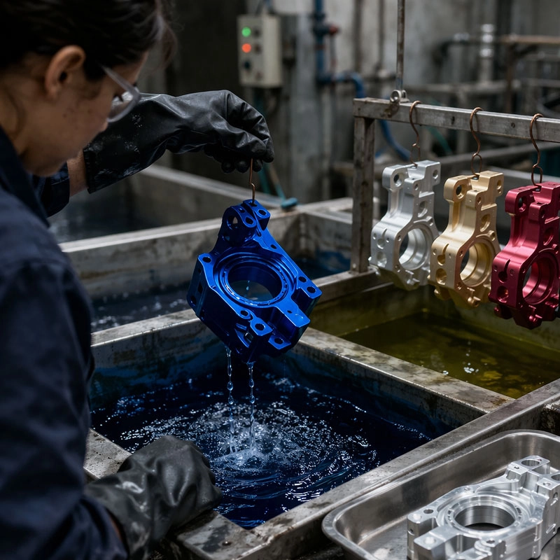
In simple terms, anodizing is an electrochemical process that thickens and toughens the natural oxide layer on aluminum. We immerse the part in an acid bath and pass an electric current through it. This causes oxygen to bond with the aluminum surface, creating a hard, porous aluminum oxide layer. This layer is integral to the metal—it won’t chip or peel like paint. For anyone looking into surface finishing for CNC parts, this is a cornerstone technology.
Superior Corrosion and Wear Resistance
This is the number one reason most folks choose anodizing. That aluminum oxide layer is incredibly resistant to rust and corrosion. Whether your part is destined for a humid environment, will handle chemicals, or just needs to withstand daily handling, anodizing acts as a shield. It’s far more effective than leaving the metal bare or using some other thin coatings. It’s the go-to method for improving corrosion resistance of machined components.
Aesthetic Versatility and Color Options
Who says protection can’t be pretty? The porous anodized layer can be dyed virtually any color before it’s sealed. From sleek blacks and vibrant reds to subtle bronzes and clear finishes that highlight the machined texture, the options are vast. This aluminum anodizing for appearance benefit is why you see it everywhere from consumer electronics to high-end automotive trim. It gives your product a professional, finished look that raw metal simply can’t match.
Improved Surface Hardness and Durability
That anodized coating is remarkably hard—often harder than tool steel. This dramatically increases the surface hardness of your aluminum part, making it highly resistant to scratches, abrasion, and general wear and tear. It’s perfect for components that experience friction, like housings, gears, or fixtures. If you’re aiming for increased durability of CNC aluminum, this process is a game-changer. The part maintains its dimensional accuracy from machining but gains a much tougher skin.
Enhanced Adhesion for Paint and Glue
Here’s a benefit you might not have considered. That slightly porous anodized surface is fantastic for bonding. If you need to apply paint, powder coat, or adhesive later on, the anodized layer provides a perfect “tooth” for these materials to grip onto. This makes anodizing as a pretreatment an excellent step in multi-stage finishing processes, ensuring your secondary coatings last as long as possible without peeling.
Electrical Insulation Properties
Aluminum oxide is an excellent electrical insulator. By creating a controlled, consistent oxide layer, anodizing can electrically isolate your aluminum part. This is crucial in electronics enclosures, heat sinks that need isolation, or any application where preventing electrical short circuits is important. It’s a functional benefit that goes hand-in-hand with the physical protection.
The Post-Machining Anodizing Process: A Quick Guide
Wondering how it all comes together after the chips are cleared away? The CNC to anodizing workflow is straightforward but requires attention to detail. First, the machined part must be thoroughly cleaned to remove all oils, coolants, and fingerprints. Then, it undergoes the anodizing bath, dyeing (if color is desired), and finally a sealing step to lock everything in. Partnering with a knowledgeable shop that understands machining and finishing services is key to a flawless result.
Key Steps Before You Anodize
Preparation is everything! After machining, we always recommend a good deburring and a thorough cleaning process. Any contaminant left on the surface can cause uneven coloring or poor adhesion of the oxide layer. Also, consider your part’s design: sharp inside corners can be tricky for the anodizing bath to reach evenly. A quick chat with your finisher during the design phase can save headaches later. For more on surface preparation standards, you can refer to resources from ASTM International.
Clearing Up Common Anodizing Myths
Let’s tackle a couple of misconceptions head-on. First, anodizing does not add a thick layer that ruins precision tolerances. Type II anodizing typically adds only 0.0001″ to 0.001″ per surface—something easily accounted for in the machining stage. Second, while it’s incredibly durable, it’s not indestructible; a hard enough impact can crack the coating. And finally, it works best on aluminum and its alloys. For more detailed technical FAQs, the Aluminum Anodizers Council is a fantastic resource.
Your Next Step: A Perfect Finish
As you can see, anodizing after CNC machining is far more than a final polish. It’s a strategic decision that unlocks durability, beauty, and functionality. Whether you’re protecting a prototype or finishing a production run, it elevates the quality and longevity of your part. So, after your next machining job, consider giving your creation this powerful upgrade. You’ll be amazed at the difference a professional aluminum surface treatment can make.
Working with heat-resistant superalloys can feel like a tough challenge for any CNC shop. These materials are incredibly strong at high temperatures, but that same strength makes them difficult to machine. This guide breaks down the process into five practical, expert-backed tips to help you achieve better finishes, longer tool life, and greater success on your next job.
Before we dive into the tips, let’s get on the same page about what we’re dealing with. When we talk about machining high-temperature alloys like Inconel, Hastelloy, or Waspaloy, we’re facing a unique set of obstacles. It’s not just harder steel; it’s a different ball game. I like to think of it as trying to carve a piece of hardened gum—it’s gummy, it work-hardens quickly, and it loves to eat cutting tools for breakfast. Successfully processing heat-resistant superalloys starts with respecting these inherent properties.
What Makes Them So Tough?
The main hurdles come down to three things: incredible strength at elevated temperatures, a tendency to work-harden, and low thermal conductivity. While their ability to retain strength under heat is why they’re used in jet engines and turbines, it means they resist cutting forces fiercely. The low thermal conductivity is a double-edged sword; instead of the heat flowing into the chip, it stays concentrated at the cutting edge, accelerating tool wear. Understanding this is the first step to choosing the right strategy.
Tip 1: Master Your Tool Selection
This is arguably the most critical step. Using the wrong tool is a fast track to frustration and wasted money. For cutting refractory metals and superalloys, you need tools that are as tough as the material itself. We strongly recommend premium-grade carbide inserts with specialized coatings. Look for grades designed for high-temperature alloys, often with a tough substrate and a PVD (Physical Vapor Deposition) coating like AlTiN. These coatings provide excellent heat resistance and lubricity. For some operations, especially finishing, you might explore CBN (Cubic Boron Nitride) tools. They’re more expensive but can be game-changers for achieving fine surface finishes on hardened alloys. A great resource for understanding advanced tool materials is the ASM International website.
Tip 2: Dial in Your Cutting Parameters
Forget the speeds and feeds you use for aluminum or mild steel. With nickel-based superalloy machining, the rules change. The golden rule here is to maintain a consistent, controlled chip load to manage heat and prevent work hardening. We suggest starting with a lower surface speed (SFM) than you initially think, but with a moderately high feed rate. This creates thicker chips that carry away heat more effectively. A light depth of cut can often lead to more rubbing and heat generation, so don’t be afraid to take a more substantial, but controlled, cut. It’s all about finding that sweet spot where the tool is working efficiently without overheating.
Tip 3: Prioritize Rigidity and Cooling
Any chatter or vibration is your enemy when fabricating with high-performance alloys. Ensure your workpiece is clamped as securely as possible using sturdy vises, fixtures, or even custom workholding. Next, let’s talk coolant. This isn’t optional; it’s essential. Use a high-quality, high-pressure coolant system aimed directly at the cutting zone. The goal is twofold: to remove heat and to help evacuate chips. Flood coolant is good, but through-tool coolant is even better as it gets right to the heart of the heat. Proper chip evacuation is crucial, as recutting chips is a surefire way to ruin your insert and your part finish.
Tip 4: Optimize Your Toolpaths and Strategy
How you move the tool is just as important as the tool itself. Modern CAM software offers powerful strategies for tough materials. For roughing, consider trochoidal or high-efficiency milling paths. These use a constant engagement angle, which provides a smoother, cooler cut compared to traditional zig-zag patterns that can shock the tool. When finishing, use climb milling to ensure the chip is thickest at the start and thin at the end, promoting a cleaner shear. Always program a lead-in and lead-out arc to avoid dwell marks. Think of your toolpath as a roadmap for managing stress on both the tool and the material.
Tip 5: Don’t Skimp on Inspection and Machine Care
This final tip is about diligence. Superalloy component manufacturing is precise work. Implement in-process checks to catch any deviation early, especially since these materials are so costly. Regularly check your tool for wear—don’t wait for it to fail completely. A slightly worn tool in a superalloy can quickly lead to work hardening on the part surface. Furthermore, keep your machine tool in top condition. Check for spindle runout and ensure way covers are clean. A well-maintained machine provides the stable platform you need for success. For official standards on material properties and testing, the ASTM International portal is an authoritative reference.
Wrapping It Up: Your Path to Success
Tackling heat resistant alloy fabrication doesn’t have to be a nightmare. By focusing on these five pillars—selecting the right tools, dialing in conservative but effective parameters, ensuring rock-solid rigidity and cooling, using smart toolpaths, and maintaining rigorous inspection habits—you’ll turn a daunting job into a repeatable process. Start by applying one or two of these tips to your next project. You’ll likely notice an improvement in tool life and part quality, giving you the confidence to master even the toughest alloys on your CNC floor. Happy machining!
While CNC machining is a cornerstone of modern manufacturing, it’s not a perfect solution for every project. This article explores the less-discussed drawbacks of CNC technology, from high initial costs to design limitations, to help you make a fully informed decision for your production needs.
Exploring the Limitations and Drawbacks of CNC Machining
Hey there! If you’re considering CNC machining for a project, you’ve probably heard all about its amazing precision and repeatability. And it’s true—computer numerical control has revolutionized how we make things. But today, I want to have a friendly chat about the other side of the coin. Every technology has its trade-offs, and understanding the disadvantages of CNC milling and turning is just as important as knowing its strengths. Let’s pull back the curtain on some of the hidden costs and constraints you should be aware of before you dive in.
1. The High Initial Investment
Let’s start with the big one: cost. When we talk about the drawbacks of CNC machining, the upfront financial commitment is often the most significant barrier. It’s not just about buying a machine; it’s about building an entire ecosystem around it.
Machine and Tooling Costs
The price tag on a high-quality industrial CNC mill or lathe can be staggering. We’re talking tens to hundreds of thousands of dollars. Beyond the machine itself, you need a library of cutting tools, workholding fixtures like vises and chucks, and a steady supply of coolants and lubricants. A friend who runs a small job shop once told me, “Buying the machine felt like buying a house. Outfitting it felt like furnishing one!” This is a key part of the CNC machining pros and cons analysis—the “con” of capital expenditure is very real.
Software and Skilled Labor
Your shiny new machine is useless without the brains to run it. You’ll need Computer-Aided Manufacturing (CAM) software to translate your designs into machine instructions (G-code). Licenses for professional-grade software are a major ongoing cost. More importantly, you need skilled programmers and operators. Finding someone who truly understands feeds, speeds, toolpaths, and machine kinematics is challenging and expensive. This human element is a critical, and often overlooked, limitation of CNC technology.
2. Design and Geometry Limitations
CNC machining is a subtractive process, meaning it carves your part out of a solid block. This fundamental approach creates some inherent CNC manufacturing disadvantages related to what shapes you can actually create.
The Challenge of Internal Geometry
Imagine trying to carve the inside of a hollow ball with a straight tool—it’s nearly impossible. That’s the core issue. CNC tools are rigid and typically access the workpiece from the top or sides. This makes features like internal channels, undercuts, or complex internal lattices extremely difficult or sometimes impossible to produce without designing multiple parts for assembly. If your design has lots of hidden or enclosed cavities, you might hit a wall. This is a classic example of a CNC machining design constraint.
Inherent Material Waste
Since you start with a solid block and remove everything that isn’t your part, you generate chips—a lot of them. For parts with a high buy-to-fly ratio (like an aerospace bracket made from a large billet of titanium), the material waste can be significant and costly. This isn’t just about money; it’s an environmental consideration too. While recycling chips is possible, the energy and material loss from subtractive manufacturing drawbacks is a valid point against CNC for certain applications, especially when compared to additive processes like 3D printing.
3. Operational and Practical Drawbacks
Beyond cost and design, the day-to-day reality of running CNC equipment comes with its own set of challenges. These are the practical problems with CNC machines that shop managers deal with regularly.
Setup and Programming Time
CNC is fantastic for repeat production, but for one-off prototypes or very small batches, the setup time can kill your efficiency. You have to design the part, program the toolpaths, simulate the run, select and set up tools, and fixture the workpiece perfectly. For a single part, this preparatory work can take longer than the actual machining time. This is why for quick prototypes, many makers still turn to manual machining or other processes. The question “what are the negatives of CNC milling?” often has “lead time for first articles” as a top answer.
Maintenance and Potential Downtime
CNC machines are complex mechanical systems with spindles, ball screws, linear guides, and a sophisticated control system. They require regular, preventative maintenance—lubrication, calibration, and component inspection—to maintain their famed accuracy. When a critical component fails, the machine is down, and production stops. Diagnosing and repairing these systems often requires specialized technicians, leading to costly downtime. It’s a reminder that the precision of computer numerical control machining comes with a need for meticulous care. For reliable information on machine maintenance standards, you can refer to resources from institutions like the National Institute of Standards and Technology (NIST).
4. Making an Informed Choice
So, after all this, is CNC machining a bad choice? Absolutely not! It’s an incredible technology. The goal here isn’t to scare you away but to empower you with a balanced view. Knowing these CNC machining challenges allows you to ask the right questions: Is my design suitable for subtractive manufacturing? Does my production volume justify the setup and programming time? Can my budget handle the machine investment and skilled labor?
For high-precision, high-strength metal parts in medium to high volumes, CNC is often unbeatable. But for highly complex organic shapes in low volume, 3D printing might be better. For very simple parts in huge quantities, injection molding could win on cost per part. My advice? View CNC as one powerful tool in a vast manufacturing toolbox. By understanding its limitations and drawbacks, you can use it more effectively and know when to choose a different tool for the job. Always start with your part’s requirements and work backward to the process—not the other way around.
When you’re planning a new project, choosing the right manufacturing method is crucial. CNC machining offers a powerful set of benefits that can save you time, money, and headaches. Let’s explore the top five advantages of using CNC technology and see how it can make your next idea a reality.
One of the biggest benefits of CNC milling and turning is the incredible accuracy it delivers. We’re talking about tolerances within thousandths of an inch, something nearly impossible to achieve consistently by hand. This precision is controlled by computer programs, meaning every single part in a run is virtually identical to the last. Whether you need ten parts or ten thousand, you can trust they will all fit and function exactly as designed. This eliminates the “part variation” headache that can stall assembly lines and derail project timelines.
How This Precision Works for You
Imagine you’re creating a custom drone frame. The motor mounts need to be perfectly aligned, or you’ll get vibration and poor performance. With computer numerical control machining, the machine follows the digital blueprint to the letter, drilling each mounting hole in the exact same spot on every frame. This level of CNC manufacturing accuracy is why industries from aerospace to medical devices rely on it for critical components. It turns complex designs into reliable, repeatable reality.
Incredible Efficiency and Speed
Once the program is set, a CNC machine can work tirelessly—24/7 if needed—with minimal supervision. This automation translates directly into faster production times compared to manual machining. What might take a skilled machinist hours to complete can often be done in a fraction of the time. Plus, modern machines can often perform multiple operations (like milling, drilling, and tapping) in a single setup. This efficiency is a major reason why CNC machining benefits businesses by shortening lead times and getting products to market faster. You’re not just buying a part; you’re buying back valuable time.
Remarkable Material and Design Versatility
Wondering about the advantages of CNC over traditional machining when it comes to materials? The range is astounding. From metals like aluminum, steel, and titanium to various plastics and even woods, CNC systems can handle them all. This flexibility extends to design complexity as well. Intricate 3D contours, deep pockets, and fine details that would be costly or impossible with manual methods are standard fare for a 5-axis CNC mill. This opens up a world of possibilities for innovative product design and functional prototyping. You’re truly limited only by your imagination (and the laws of physics!).
Enhanced Safety and Reduced Labor Intensity
This is a significant but often overlooked perk. In CNC machine shop operations, the operator’s primary role is to monitor the process, load materials, and perform quality checks—not to stand directly over a spinning cutter. The cutting happens inside an enclosed workspace, dramatically reducing the risk of accidents associated with manual lathes or mills. This creates a safer work environment and allows skilled personnel to focus on programming, optimization, and quality assurance rather than repetitive, physically demanding tasks. It’s a smarter, safer way to build things.
Excellent Scalability for Any Volume
Whether you need a one-off prototype or a full production run, CNC is a fantastic choice. For prototyping, you can quickly iterate designs by simply modifying the digital file. When you’re ready for production, that same file can run to manufacture hundreds or thousands of identical parts with ease. This seamless transition from CNC prototyping advantages to full-scale manufacturing makes it a uniquely scalable solution. You don’t need to switch processes or retool extensively, which saves money and maintains consistency across your entire product lifecycle. It’s as suitable for a startup’s first batch as it is for an established company’s ongoing needs.
Key Benefits of CNC Machining for Modern Manufacturing
So, what does all this mean for your project? In short, CNC machining provides a reliable, precise, and flexible foundation for bringing ideas to life. The combination of digital accuracy, material flexibility, and efficient production empowers designers and engineers to solve problems in new ways. By leveraging these top advantages of CNC technology, you can reduce costs, accelerate development, and produce higher-quality parts. It’s a cornerstone of modern making, turning complex digital designs into tangible, high-performance objects you can hold in your hand. Ready to see what it can do for you?
Starting your first CNC project can feel overwhelming, but it’s an incredibly rewarding journey. This guide breaks down the essential steps, from understanding the basics of computer numerical control to choosing your first simple design. We’ll walk you through the core concepts and practical tips to turn your digital idea into a physical part with confidence.
Getting Started with CNC: Essential Fundamentals for New Machinists
Welcome! If you’re curious about CNC machining for beginners, you’re in the right place. Think of learning computer numerical control like learning to drive. First, you need to know what the pedals and steering wheel do before you hit the open road. This section covers those fundamentals, so you understand the “why” behind the “how.” It’s the best way to build a solid foundation for your first CNC project and avoid common frustrations.
What Exactly is CNC Machining?
At its heart, CNC milling or CNC turning is a process where a computer controls machine tools. You create a digital design, and the machine follows those instructions with incredible precision to cut away material. It’s a form of subtractive manufacturing, which is a fancy way of saying you start with a block of material and carve your part out of it. This is different from 3D printing (additive manufacturing), where material is added layer by layer.
The Key Components of Your CNC Workflow
Your journey from idea to object involves three main stages, often called the CAD-CAM-CNC chain. First, CAD (Computer-Aided Design) is where you draw your part using software. Next, CAM (Computer-Aided Manufacturing) software takes that drawing and creates the toolpaths—the detailed instructions for the machine’s movements. Finally, the CNC controller reads those instructions and drives the motors to make the cuts. Understanding this flow is crucial for anyone starting CNC machining as a hobby.
Planning Your First CNC Machining Project
Jumping straight into a complex design is a recipe for discouragement. Successful beginner CNC projects are all about smart planning. This phase is where you set yourself up for a win by making thoughtful choices about your design and material. A little planning here saves a lot of troubleshooting later.
Choosing the Perfect Beginner-Friendly Design
We suggest you start with something flat and 2.5D. A simple nameplate, a coaster, or a basic bracket are fantastic first projects for CNC. These designs typically use profile cuts (cutting out the outline) and pocketing (clearing out areas), which teach you the core operations without needing complex 3D toolpaths. Avoid designs with tiny, delicate details or steep overhangs for now. You can find great free CNC projects for starters on sites like Thingiverse.
Material Selection: Start Simple for Success
Your material choice dramatically affects your experience. For your very first attempt, I highly recommend using wood (like pine or poplar) or a soft plastic like HDPE or acrylic. These materials for new CNC users are forgiving—they cut easily, are less stressful on your tools, and are cheaper if you make a mistake. Save metals like aluminum for when you’re more comfortable with the process. Remember, the goal of learning CNC machining is to learn the process, not to fight a tough material.
From CAD to Part: The Digital Workflow Simplified
This is where your project comes to life on the screen before it touches the machine. The digital workflow transforms your idea into a language the CNC understands. While it might seem technical, modern software makes CNC programming for novices more accessible than ever.
You’ll use CAD software to draw your part. For beginners, free options like Fusion 360 (for personal use) or Tinkercad are excellent starting points. Once your design is ready, you switch to the CAM workspace within the same software or a dedicated program. Here, you’ll select the tool (like an end mill), define the cutting speeds and feeds (how fast the tool spins and moves), and generate the G-code. This G-code is the final set of instructions. A common tip is to always simulate the toolpath in the software first—it’s like a dry run that can prevent a costly crash on the actual machine.
Machine Setup and Safe Operation Practices
Now for the hands-on part! Proper setup is non-negotiable for safety and quality. This involves securing your material to the machine bed (we call this “workholding”), installing and measuring the correct cutting tool, and setting the machine’s zero points. Rushing this step is the biggest mistake beginners make.
Always, always wear safety glasses. Secure your material rock-solid; if it moves, the part is ruined and it can be dangerous. Use clamps or a vise. Then, you’ll “touch off” your tool to set the X, Y, and Z zero positions, telling the machine exactly where the material is. This process, part of basic CNC operation, ensures the machine cuts in the right place. Double-check everything before you start the spindle. For comprehensive safety guidelines, refer to resources from OSHA.
Launching Your Cut and Learning from the Process
Take a deep breath and hit start! It’s normal to be nervous. Stay by the machine for the first few moments, ready to hit the emergency stop if something sounds or looks wrong (like a loud bang or the material vibrating loose). Listen to the sound of the cut—a smooth, consistent sound is good; screeching or chattering means something might be off.
Your first part might not be perfect, and that’s okay. The real goal of your introductory CNC guide is the learning. Did the tool leave rough marks? Maybe the feed rate was too high. Did a thin part break? Perhaps you needed a different workholding strategy. Each “mistake” is a valuable lesson that makes your next project better. Document what you did, the settings you used, and the outcome. Before you know it, you’ll have the confidence and skills to tackle more advanced CNC router projects for beginners and beyond. You’ve just taken the first step into the amazing world of making things with precision!
Ever wondered how complex metal or plastic parts are made with such incredible precision? The answer lies in CNC machining. This guide breaks down the entire CNC manufacturing process into simple steps, from a digital design to a finished physical part. We’ll explore how it works, why it’s so valuable, and clear up some common misconceptions.
Understanding the Step-by-Step CNC Machining Workflow
Let’s walk through the CNC machining process step by step. Think of it like a highly skilled chef following a perfect recipe. The recipe is the digital design, the chef is the machine, and the ingredients are your block of material. Every action is planned and executed with precision.
Step 1: The Digital Blueprint (CAD)
It all starts with an idea. Using Computer-Aided Design (CAD) software, an engineer or designer creates a detailed 3D model of the part. This is the master plan. It defines every dimension, curve, and hole. You might be asking, how does CNC machining work from a drawing?” Well, this 3D model is the essential first answer. It’s the source of truth for the entire CNC manufacturing process.
Step 2: Speaking the Machine’s Language (CAM)
The CAD model is beautiful, but the machine can’t understand it directly. This is where Computer-Aided Manufacturing (CAM) software comes in. The CAM programmer takes the 3D model and creates a set of instructions, called G-code. This code tells the machine exactly where to move, how fast to spin the cutting tool, and how deep to cut. It’s like translating the recipe into a language the chef understands perfectly.
Step 3: The Machine Setup
Now, we move to the shop floor. An operator secures the raw material (called the “workpiece”)—which could be aluminum, steel, plastic, or other materials—onto the machine bed. The correct cutting tools are loaded into the machine’s spindle. This setup is crucial for accuracy. A good setup ensures the CNC milling process or CNC turning operation starts from the right place every time.
Step 4: The Machining Operation
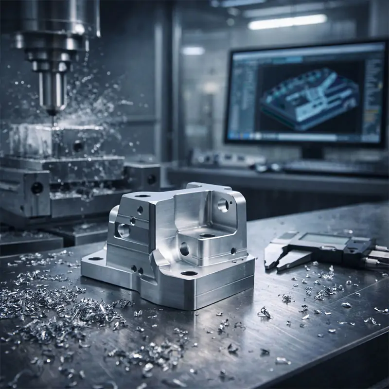
This is the main event! The machine operator starts the program. The spindle spins the cutting tool at high speeds, and it precisely removes material from the workpiece, following the paths defined by the G-code. You’ll see chips flying as the block of material is gradually shaped into the final part. Different operations like milling, drilling, and turning happen here, all part of the subtractive manufacturing family.
Step 5: Finishing Touches
Once the main cutting is done, the part often isn’t quite ready. It might have sharp edges or a rough surface. Secondary processes like deburring (removing sharp edges), sanding, polishing, or anodizing (for aluminum) are applied. This post-processing gives the part its final look, feel, and sometimes extra properties like corrosion resistance.
Why is the CNC Process So Valuable?
So, what makes this explanation of CNC machining so important for industries? The value is immense. First, it offers incredible precision and repeatability. You can make one part or a thousand, and they will all be virtually identical. This is a game-changer for everything from aerospace components to medical devices. Second, it can create incredibly complex geometries that would be impossible or prohibitively expensive to make by hand. Finally, while the initial setup and programming take time, it’s extremely efficient for production runs, saving both time and money in the long run. For a deeper dive into its applications, resources like the American Society of Mechanical Engineers (ASME) offer great insights.
How Can You Get Started with CNC Manufacturing?
If you’re curious about using CNC machining services for a project, here’s our friendly advice. Start with a clear and well-designed CAD file—this is the most important piece. Then, find a reputable machine shop. Don’t be afraid to ask questions! A good shop will guide you on material selection, design for manufacturability (making sure your design is easy to machine), and cost estimates. For beginners, starting with a simpler design in a common material like 6061 aluminum is a great way to learn the basics of CNC operation without breaking the bank.
Clearing Up Common CNC Machining Misconceptions
Let’s tackle a few myths. First, some think CNC is only for huge factories. Not true! Many small workshops and even hobbyists use desktop CNC machines. Second, it’s not always the fastest option for a single, simple part—3D printing might be quicker for a one-off prototype. Third, while highly automated, it still requires skilled humans for programming, setup, and quality control. The machine follows instructions; people provide the expertise. Understanding these nuances is key to a complete guide to computer numerical control.
In short, the CNC machining process is a powerful blend of digital design and physical precision. By understanding the workflow from CAD to finished part, you can appreciate its role in making the world around us, from your car’s engine to your smartphone’s casing. It’s a fascinating technology that turns digital dreams into tangible reality.
Ever wondered how complex metal or plastic parts are made with such incredible precision? The answer often lies in CNC machining. This guide will walk you through what CNC machining is, how it works, and why it’s a cornerstone of modern manufacturing, all in simple, friendly terms.
Let’s start at the very beginning. If you’ve ever seen a perfectly smooth engine block, a custom guitar bridge, or even parts of a smartphone, you’ve likely seen the work of CNC manufacturing. At its heart, computer numerical control machining is a way to make things by removing material from a solid block, guided entirely by a computer. Think of it like a super-precise, automated sculptor that can carve metal, plastic, or wood based on a digital blueprint.
What Does CNC Stand For?
CNC stands for Computer Numerical Control. It sounds technical, but it’s quite straightforward. The “computer” part is the brain—it reads a set of coded instructions (called G-code). The “numerical control” part refers to how those instructions tell the machine exactly where to move, how fast to spin the cutting tool, and how deep to cut. Before CNC, machinists had to manually operate machines like lathes and mills, which was slower and less consistent. So, when people ask what is CNC milling or what is CNC turning, they’re really asking about specific applications of this brilliant computer-controlled system.
How Does the CNC Machining Process Work?
The journey from a raw block to a finished part is a fascinating dance between software and hardware. It usually starts with a 3D model designed in CAD (Computer-Aided Design) software. This model is then translated by CAM (Computer-Aided Manufacturing) software into the G-code the machine understands. Once the code is loaded, the operator secures the material (called the workpiece) onto the machine bed. Then, with the push of a button, the machine’s cutting tools follow the programmed path with incredible accuracy, shaving away material layer by layer until the part is complete. This process is the core of subtractive manufacturing, which is just a fancy term for carving out a shape.
CNC Milling vs. CNC Turning
You’ll often hear about two main types of CNC machine tools: mills and lathes. Here’s a simple way to tell them apart. A CNC milling service typically uses a rotating cutting tool that moves across a stationary workpiece to cut away material. It’s great for creating complex shapes, slots, and holes. On the other hand, CNC lathe work involves rotating the workpiece itself against a stationary cutting tool. This is ideal for making cylindrical or conical parts like shafts, knobs, and rings. Many modern workshops use multi-axis machining centers that can do both, offering incredible flexibility.
Why CNC Machining is a Game-Changer
So, why has precision CNC machining become so vital? First, it’s incredibly accurate and repeatable. You can produce ten parts or ten thousand, and each one will be virtually identical. This level of consistency is crucial for industries like aerospace and medical devices. Second, it can handle incredibly complex geometries that would be impossible or too expensive to make by hand. Third, while the initial setup and programming take time, it’s extremely efficient for production runs, saving time and money in the long run. It truly is a pillar of modern manufacturing techniques.
Getting Started with CNC: What You Should Know
If you’re curious about using CNC machining services, here’s some friendly advice. Start by having a clear, well-designed 3D model—this is your recipe. Next, think about your material choice; common options include aluminum, stainless steel, brass, and various plastics like ABS or nylon. Each has different properties and machining requirements. When you contact a machine shop, be ready to discuss your part’s function, required tolerances (how precise dimensions need to be), and surface finish. A good shop will guide you through the CNC fabrication process and help optimize your design for manufacturability. For a deeper dive into materials and standards, resources like ASM International can be very helpful.
Clearing Up Common CNC Misconceptions
Let’s tackle a few myths! One common belief is that CNC machines do everything by themselves without any human skill. In reality, a skilled machinist or programmer is essential for setting up the job, selecting the right tools, and ensuring everything runs smoothly. Another myth is that it’s only for giant factories. While it powers major industries, smaller CNC job shops and even hobbyists use desktop CNC machines for prototyping and custom projects. Finally, it’s not just for metal. CNC routing for wood and plastics is hugely popular in sign-making, furniture, and arts.
I hope this guide has helped demystify the world of CNC for you. From understanding what is computer numerical control to seeing its real-world impact, it’s a technology that shapes the physical world around us with precision and efficiency. Whether you’re an engineer, a maker, or just someone fascinated by how things are made, the principles of CNC machining are a wonderful glimpse into the innovation driving modern production.