Categories
Blog Design, Cost & Sourcing Industries & Applications

Multilayer PCB Guide for Mechanical Engineers: Design, Enclosures, Heat, and CNC Interfaces

Multilayer PCB Guide for Mechanical Engineers: Design, Enclosures, Heat, and CNC Interfaces is a practical manufacturing question because the answer affects cost, lead time, material behavior, inspection, and the path from prototype to production. For MTSPi CNC customers, the key is not simply naming a process, but understanding how the process connects with machined parts, fixtures, tolerances, surface requirements, and final assembly.

This guide explains multilayer PCB from an engineering and purchasing point of view. It is written for product developers, mechanical engineers, sourcing teams, and buyers who need clear decisions rather than generic process descriptions.

Quick Answer

Multilayer PCBs need early mechanical coordination. Board outline, mounting holes, keepouts, connector locations, thermal pads, and shielding requirements should be frozen before machining enclosures or fixtures.

Key Differences at a Glance

Point Option A Option B
Board outline Controls fit inside housing Use current PCB STEP or DXF data
Standoffs Affects board stress and assembly height Machine stable bosses with correct clearance
Thermal pads Moves heat from components Create flat contact surfaces and controlled gaps
Connectors Need alignment with openings Inspect port position and tolerance stack
EMI Metal can shield or interfere Plan grounding and clearance zones

How the Process Choice Affects Real Parts

A manufacturing method should be selected around the feature that actually controls function. Cosmetic surfaces, hidden support features, threads, bores, sealing faces, heat-transfer areas, and assembly datums do not carry the same risk. When those requirements are mixed together without priority, quotes become inconsistent and production becomes harder to control.

The safest workflow is to define the part requirement first, then match the process. A printed prototype may answer shape questions, a molded sample may answer appearance questions, and a CNC machined sample may answer tolerance, material, and functional questions. Many successful projects use more than one method before the final design is locked.

Design and Manufacturing Considerations

  • Import PCB STEP files into the enclosure CAD model.
  • Add tolerance around connectors based on both PCB and machining variation.
  • Avoid unsupported board spans near heavy connectors or buttons.
  • Define conductive and non-conductive contact areas clearly.
  • Use prototype enclosures to validate assembly before production.

Cost, Lead Time, and Risk Factors

Cost is driven by setup, tooling, material, machine time, inspection, finishing, and revision risk. A low unit price is not always the lowest project cost if it creates rework later. For prototypes and low-volume orders, flexibility can be more valuable than a process with a lower theoretical unit cost.

  • Use standard materials and standard feature sizes when they do not weaken the design.
  • Separate critical tolerances from general dimensions so the supplier knows where to focus.
  • Confirm surface finish and cosmetic requirements before production begins.
  • Avoid late changes to mounting holes, connector openings, datum faces, and threaded features.
  • Send CAD files and 2D drawings together when tolerances, threads, or finishes matter.

Quality Checks Before Production

A good quality plan checks the features that influence assembly and performance. Depending on the part, this may include dimensional inspection, thread gauges, surface roughness, flatness, perpendicularity, burr control, coating thickness, visual appearance, and fit with mating parts.

When This Topic Matters for CNC Buyers

multilayer PCB matters when a team is comparing prototype routes, validating a design, replacing a weak supplier, or trying to reduce manufacturing cost without damaging function. The best choice is usually the process that answers the current engineering question with the least unnecessary risk.

MTSPi CNC Engineering Notes

MTSPi CNC supports precision CNC milling, turning, rapid prototyping, low-volume production, finishing, and inspection for custom parts. If your project uses molding, casting, welding, PCB assemblies, or 3D printing, CNC machining can still be important for datums, holes, threads, sealing faces, fixtures, and production-ready prototypes.

Frequently Asked Questions

Can this process replace CNC machining?

Sometimes it can replace CNC for non-critical geometry, but CNC is often still needed when tight tolerances, real engineering material, threads, flat sealing faces, or precise mating features are required.

What files help MTSPi CNC review a project?

STEP or STP files are useful for geometry. A 2D drawing is important for tolerances, materials, threads, surface finish, inspection requirements, and notes that are not obvious from the CAD model.

How do I reduce manufacturing risk?

Define critical features, avoid unnecessary tight tolerances, confirm material and finish requirements, and use prototypes to validate assembly before committing to higher-volume tooling or production.

Related MTSPi Resources

Categories
Blog CNC Milling & Turning Design, Cost & Sourcing

Counterbore vs Countersink Holes: Design Differences, Uses, and CNC Machining Notes

Counterbore vs Countersink Holes: Design Differences, Uses, and CNC Machining Notes is a practical manufacturing question because the answer affects cost, lead time, material behavior, inspection, and the path from prototype to production. For MTSPi CNC customers, the key is not simply naming a process, but understanding how the process connects with machined parts, fixtures, tolerances, surface requirements, and final assembly.

This guide explains counterbore vs countersink from an engineering and purchasing point of view. It is written for product developers, mechanical engineers, sourcing teams, and buyers who need clear decisions rather than generic process descriptions.

Quick Answer

Use a counterbore for socket head cap screws, washers, and flat bearing seats. Use a countersink for flat-head screws where the conical head must sit flush with the surface.

Key Differences at a Glance

Point Option A Option B
Shape Cylindrical recess with flat floor Conical recess
Fastener Socket head cap screw, bolt head, washer Flat-head screw
Seat contact Flat bearing surface Angled bearing surface
Common angle Not angle-based 82, 90, or 100 degrees depending on standard
Inspection Diameter and depth Angle, major diameter, flushness

How the Process Choice Affects Real Parts

A manufacturing method should be selected around the feature that actually controls function. Cosmetic surfaces, hidden support features, threads, bores, sealing faces, heat-transfer areas, and assembly datums do not carry the same risk. When those requirements are mixed together without priority, quotes become inconsistent and production becomes harder to control.

The safest workflow is to define the part requirement first, then match the process. A printed prototype may answer shape questions, a molded sample may answer appearance questions, and a CNC machined sample may answer tolerance, material, and functional questions. Many successful projects use more than one method before the final design is locked.

Design and Manufacturing Considerations

  • Specify pilot hole diameter, counterbore diameter, counterbore depth, and tolerance where needed.
  • For countersinks, specify included angle and acceptable flushness if appearance matters.
  • Leave enough wall thickness around recessed holes to prevent breakout.
  • Avoid placing counterbores too close to edges, ribs, or deep pocket walls.
  • Match the hole callout to the actual fastener standard.

Cost, Lead Time, and Risk Factors

Cost is driven by setup, tooling, material, machine time, inspection, finishing, and revision risk. A low unit price is not always the lowest project cost if it creates rework later. For prototypes and low-volume orders, flexibility can be more valuable than a process with a lower theoretical unit cost.

  • Use standard materials and standard feature sizes when they do not weaken the design.
  • Separate critical tolerances from general dimensions so the supplier knows where to focus.
  • Confirm surface finish and cosmetic requirements before production begins.
  • Avoid late changes to mounting holes, connector openings, datum faces, and threaded features.
  • Send CAD files and 2D drawings together when tolerances, threads, or finishes matter.

Quality Checks Before Production

A good quality plan checks the features that influence assembly and performance. Depending on the part, this may include dimensional inspection, thread gauges, surface roughness, flatness, perpendicularity, burr control, coating thickness, visual appearance, and fit with mating parts.

When This Topic Matters for CNC Buyers

counterbore vs countersink matters when a team is comparing prototype routes, validating a design, replacing a weak supplier, or trying to reduce manufacturing cost without damaging function. The best choice is usually the process that answers the current engineering question with the least unnecessary risk.

MTSPi CNC Engineering Notes

MTSPi CNC supports precision CNC milling, turning, rapid prototyping, low-volume production, finishing, and inspection for custom parts. If your project uses molding, casting, welding, PCB assemblies, or 3D printing, CNC machining can still be important for datums, holes, threads, sealing faces, fixtures, and production-ready prototypes.

Frequently Asked Questions

Can this process replace CNC machining?

Sometimes it can replace CNC for non-critical geometry, but CNC is often still needed when tight tolerances, real engineering material, threads, flat sealing faces, or precise mating features are required.

What files help MTSPi CNC review a project?

STEP or STP files are useful for geometry. A 2D drawing is important for tolerances, materials, threads, surface finish, inspection requirements, and notes that are not obvious from the CAD model.

How do I reduce manufacturing risk?

Define critical features, avoid unnecessary tight tolerances, confirm material and finish requirements, and use prototypes to validate assembly before committing to higher-volume tooling or production.

Related MTSPi Resources

Categories
Blog Design, Cost & Sourcing Manufacturing Process Comparisons

SLM vs SLA: How to Choose Between Metal and Resin 3D Printing

SLM vs SLA: How to Choose Between Metal and Resin 3D Printing is a practical manufacturing question because the answer affects cost, lead time, material behavior, inspection, and the path from prototype to production. For MTSPi CNC customers, the key is not simply naming a process, but understanding how the process connects with machined parts, fixtures, tolerances, surface requirements, and final assembly.

This guide explains SLM vs SLA from an engineering and purchasing point of view. It is written for product developers, mechanical engineers, sourcing teams, and buyers who need clear decisions rather than generic process descriptions.

Quick Answer

Choose SLM when the part needs metal strength, complex internal geometry, lightweight structures, or functional metal prototypes. Choose SLA when the goal is smooth resin models, cosmetic prototypes, fit checks, or detailed concept parts at lower cost.

Key Differences at a Glance

Point Option A Option B
Material Metal powders such as aluminum, stainless, titanium Photopolymer resins
Strength Functional metal performance after correct processing Plastic-like, resin-dependent behavior
Surface Often needs post-processing Usually smooth as printed
Cost Higher machine and powder cost Lower for visual and fit prototypes
Post-processing Support removal, heat treatment, CNC finishing Cleaning, curing, sanding, painting

How the Process Choice Affects Real Parts

A manufacturing method should be selected around the feature that actually controls function. Cosmetic surfaces, hidden support features, threads, bores, sealing faces, heat-transfer areas, and assembly datums do not carry the same risk. When those requirements are mixed together without priority, quotes become inconsistent and production becomes harder to control.

The safest workflow is to define the part requirement first, then match the process. A printed prototype may answer shape questions, a molded sample may answer appearance questions, and a CNC machined sample may answer tolerance, material, and functional questions. Many successful projects use more than one method before the final design is locked.

Design and Manufacturing Considerations

  • Use SLM for metal features that cannot be made efficiently by milling or turning alone.
  • Use SLA for visual models, ergonomic checks, and assembly reviews before cutting metal.
  • Do not assume printed tolerances are the same as CNC-machined tolerances.
  • Add machining stock to SLM features that need precise bores, sealing faces, or threads.
  • Select resin by test purpose: appearance, heat resistance, transparency, or fit check.

Cost, Lead Time, and Risk Factors

Cost is driven by setup, tooling, material, machine time, inspection, finishing, and revision risk. A low unit price is not always the lowest project cost if it creates rework later. For prototypes and low-volume orders, flexibility can be more valuable than a process with a lower theoretical unit cost.

  • Use standard materials and standard feature sizes when they do not weaken the design.
  • Separate critical tolerances from general dimensions so the supplier knows where to focus.
  • Confirm surface finish and cosmetic requirements before production begins.
  • Avoid late changes to mounting holes, connector openings, datum faces, and threaded features.
  • Send CAD files and 2D drawings together when tolerances, threads, or finishes matter.

Quality Checks Before Production

A good quality plan checks the features that influence assembly and performance. Depending on the part, this may include dimensional inspection, thread gauges, surface roughness, flatness, perpendicularity, burr control, coating thickness, visual appearance, and fit with mating parts.

When This Topic Matters for CNC Buyers

SLM vs SLA matters when a team is comparing prototype routes, validating a design, replacing a weak supplier, or trying to reduce manufacturing cost without damaging function. The best choice is usually the process that answers the current engineering question with the least unnecessary risk.

MTSPi CNC Engineering Notes

MTSPi CNC supports precision CNC milling, turning, rapid prototyping, low-volume production, finishing, and inspection for custom parts. If your project uses molding, casting, welding, PCB assemblies, or 3D printing, CNC machining can still be important for datums, holes, threads, sealing faces, fixtures, and production-ready prototypes.

Frequently Asked Questions

Can this process replace CNC machining?

Sometimes it can replace CNC for non-critical geometry, but CNC is often still needed when tight tolerances, real engineering material, threads, flat sealing faces, or precise mating features are required.

What files help MTSPi CNC review a project?

STEP or STP files are useful for geometry. A 2D drawing is important for tolerances, materials, threads, surface finish, inspection requirements, and notes that are not obvious from the CAD model.

How do I reduce manufacturing risk?

Define critical features, avoid unnecessary tight tolerances, confirm material and finish requirements, and use prototypes to validate assembly before committing to higher-volume tooling or production.

Related MTSPi Resources

Categories
Blog Design, Cost & Sourcing Industries & Applications

4-Layer PCB Basics for Product Developers: Stackup, Uses, and Mechanical Design Notes

4-Layer PCB Basics for Product Developers: Stackup, Uses, and Mechanical Design Notes is a practical manufacturing question because the answer affects cost, lead time, material behavior, inspection, and the path from prototype to production. For MTSPi CNC customers, the key is not simply naming a process, but understanding how the process connects with machined parts, fixtures, tolerances, surface requirements, and final assembly.

This guide explains 4-layer PCB from an engineering and purchasing point of view. It is written for product developers, mechanical engineers, sourcing teams, and buyers who need clear decisions rather than generic process descriptions.

Quick Answer

A 4-layer PCB is often chosen when compact routing, EMI behavior, power distribution, or product reliability requires more than a simple two-layer board. Mechanical design should be coordinated with PCB outline, connector location, heat path, and mounting strategy early.

Key Differences at a Glance

Point Option A Option B
Top layer Components and signal routing Connector height and assembly access
Inner layer 1 Ground plane Shielding and reference stability
Inner layer 2 Power plane or signals Thermal and current planning
Bottom layer Signals and secondary components Clearance to housing, screws, and brackets

How the Process Choice Affects Real Parts

A manufacturing method should be selected around the feature that actually controls function. Cosmetic surfaces, hidden support features, threads, bores, sealing faces, heat-transfer areas, and assembly datums do not carry the same risk. When those requirements are mixed together without priority, quotes become inconsistent and production becomes harder to control.

The safest workflow is to define the part requirement first, then match the process. A printed prototype may answer shape questions, a molded sample may answer appearance questions, and a CNC machined sample may answer tolerance, material, and functional questions. Many successful projects use more than one method before the final design is locked.

Design and Manufacturing Considerations

  • Confirm PCB outline, mounting hole diameter, and keepout zones before machining an enclosure.
  • Use realistic clearance around connectors, switches, displays, LEDs, and cable exits.
  • Plan thermal interfaces when power components need contact with a machined heat sink.
  • Avoid placing conductive metal features too close to exposed pads or antenna zones.
  • Ask for updated board files before cutting production fixtures or housings.

Cost, Lead Time, and Risk Factors

Cost is driven by setup, tooling, material, machine time, inspection, finishing, and revision risk. A low unit price is not always the lowest project cost if it creates rework later. For prototypes and low-volume orders, flexibility can be more valuable than a process with a lower theoretical unit cost.

  • Use standard materials and standard feature sizes when they do not weaken the design.
  • Separate critical tolerances from general dimensions so the supplier knows where to focus.
  • Confirm surface finish and cosmetic requirements before production begins.
  • Avoid late changes to mounting holes, connector openings, datum faces, and threaded features.
  • Send CAD files and 2D drawings together when tolerances, threads, or finishes matter.

Quality Checks Before Production

A good quality plan checks the features that influence assembly and performance. Depending on the part, this may include dimensional inspection, thread gauges, surface roughness, flatness, perpendicularity, burr control, coating thickness, visual appearance, and fit with mating parts.

When This Topic Matters for CNC Buyers

4-layer PCB matters when a team is comparing prototype routes, validating a design, replacing a weak supplier, or trying to reduce manufacturing cost without damaging function. The best choice is usually the process that answers the current engineering question with the least unnecessary risk.

MTSPi CNC Engineering Notes

MTSPi CNC supports precision CNC milling, turning, rapid prototyping, low-volume production, finishing, and inspection for custom parts. If your project uses molding, casting, welding, PCB assemblies, or 3D printing, CNC machining can still be important for datums, holes, threads, sealing faces, fixtures, and production-ready prototypes.

Frequently Asked Questions

Can this process replace CNC machining?

Sometimes it can replace CNC for non-critical geometry, but CNC is often still needed when tight tolerances, real engineering material, threads, flat sealing faces, or precise mating features are required.

What files help MTSPi CNC review a project?

STEP or STP files are useful for geometry. A 2D drawing is important for tolerances, materials, threads, surface finish, inspection requirements, and notes that are not obvious from the CAD model.

How do I reduce manufacturing risk?

Define critical features, avoid unnecessary tight tolerances, confirm material and finish requirements, and use prototypes to validate assembly before committing to higher-volume tooling or production.

Related MTSPi Resources

Categories
Blog Design, Cost & Sourcing Quality & Tolerances

Bolt vs Screw vs Rivet vs Nut: Fastener Choices for CNC Parts

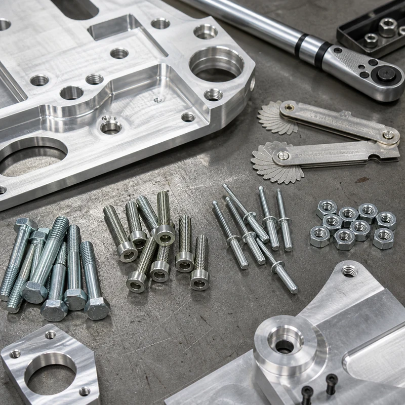
Bolts, screws, rivets, and nuts all join parts, but they do it in different ways. Choosing the wrong fastener can create assembly delays, weak clamping, damaged threads, difficult maintenance, or unnecessary machining cost.

For CNC machined parts, fastener selection should be reviewed with material, wall thickness, access direction, thread depth, tolerance, finish, and service load. These details are best included early in CNC machining drawings rather than solved after parts are cut.

Quick Comparison

Fastener How it works Typical connection CNC design note
Bolt External thread clamps parts, usually with a nut Removable Needs clearance holes, access, and suitable bearing area.
Screw Threads into a tapped hole or directly into material Removable Needs thread engagement and enough wall thickness.
Rivet Deforms during installation to lock parts together Permanent Useful when future disassembly is not expected.
Nut Internal thread pairs with a bolt or threaded rod Removable threaded joint Needs wrench access and anti-loosening plan if vibration exists.

When to Use Bolts

Bolts are useful when a strong, serviceable joint is needed. They are common in machine frames, fixtures, housings, structural brackets, and assemblies that need maintenance access. A bolt usually works with a nut, although a tapped component can sometimes replace the nut.

In CNC parts, designers should confirm head clearance, tool access, washer or bearing surface, grip length, and whether the bolt will load the part in tension, shear, or both.

When to Use Screws

Screws are often chosen when the assembly is compact or when the fastener must thread directly into the machined part. Machine screws in tapped holes are common in covers, enclosures, instrument housings, panels, and precision fixtures.

The key design issue is thread engagement. Soft materials such as aluminum or plastic may need more thread depth, inserts, or a larger diameter. MTSPi can review material choice through CNC material options before the threaded features are finalized.

When to Use Rivets

Rivets create a permanent mechanical joint. They can be useful for sheet metal, light structures, covers, and assemblies where loosening must be avoided and future disassembly is not required. Some rivets can be installed from one side, which helps when rear access is limited.

The tradeoff is repairability. Removing a rivet usually damages or changes the joint, so rivets should not be used where routine service, adjustment, or repeated inspection access is expected.

What Nuts Add to an Assembly

Nuts are not usually used alone. They complete a threaded joint with a bolt or threaded rod. Hex nuts, lock nuts, flange nuts, and prevailing-torque nuts solve different access and vibration problems.

For CNC machined assemblies, nut access should be checked in the model. A strong joint on paper can become expensive if there is no room for a socket, wrench, washer, or locking feature.

Design Checks for CNC Machined Fastener Features

Design check Why it matters Practical action
Thread depth Too little engagement can strip threads Match thread length to material and load.
Edge distance Holes too close to edges can crack or deform Leave enough material around holes.
Counterbore and countersink Head style affects surface fit and tool access Call out dimensions clearly on the drawing.
Vibration Threaded joints can loosen Consider lock nuts, thread lockers, washers, or rivets.
Finish buildup Coatings can affect threads and holes Plan masking or post-finish thread checks.

Fastener choices also affect machining cost. Extra tapped holes, deep threads, tight position tolerances, and difficult counterbores can increase cycle time. Review these details with reduce CNC machining cost if the assembly has many fasteners.

Conclusion

Use bolts for strong removable joints, screws for compact threaded fastening, rivets for permanent connections, and nuts to complete bolted assemblies. The best choice depends on load, access, service needs, material, and machining cost. Define the fastener strategy early so the CNC parts are easier to make, inspect, assemble, and maintain.

Categories
Blog Design, Cost & Sourcing Quality & Tolerances

CNC Supplier Audit Checklist for Reliable Part Production

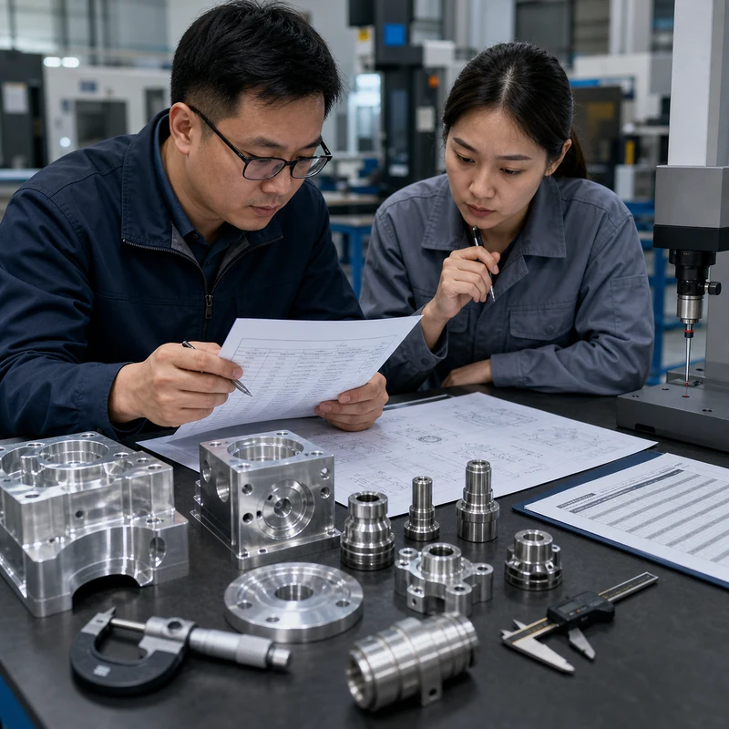
A CNC supplier audit is the practical bridge between a promising quotation and dependable production. Instead of judging a machine shop only by sample photos or unit price, engineers and sourcing teams should verify whether the supplier can repeatedly meet drawing requirements, manage material risk, document inspection results, and communicate clearly when something changes.

MTSPi supports prototype and production programs through CNC machining services, including milling, turning, 5-axis work, finishing coordination, and documented inspection. The checklist below is written as a reusable audit framework that buyers can apply when qualifying any machining partner for new work.

Supplier Audit Snapshot

Start with a short cross-functional review before going deep into drawings or pricing. A first-pass audit should tell you whether the supplier deserves a technical follow-up, an on-site visit, or a pilot order.

Audit Area What You Need to Confirm Why It Matters
Process fit The available machines and setups match your part geometry Capability gaps create rework, outsourcing, and lead-time risk
Quality system Incoming, in-process, and final inspection are defined Repeatable quality needs more than a final measurement
Material control Traceability, certificates, and storage practices are in place Wrong or mixed material can invalidate the whole build
Engineering support The supplier can review manufacturability and tolerance drivers Early DFM feedback reduces avoidable cost and scrap
Production control Capacity, scheduling, tooling, and revision control are visible A good sample does not guarantee stable repeat production
Communication Technical questions, updates, and escalation paths are clear Most schedule slips start as communication failures

1. Verify Process Capability Against the Actual Part

An audit should begin with the part family you want to buy, not with a generic machine list. A supplier may own advanced equipment but still be a weak fit for thin-wall enclosures, tight-runout shafts, or multi-face brackets that need accurate datum transfer.

Part Type Capability to Look For Audit Question
Prismatic plates and housings 3-axis or indexed 4-axis milling How are flatness, hole position, and burr control checked?
Multi-side complex features 4-axis or 5-axis machining How is setup error reduced across multiple faces?
Rotational parts CNC turning, mill-turn, or Swiss machining How are concentricity, runout, and thread quality controlled?
Deep cavities or difficult access Long-reach tooling strategy and simulation What risks exist for chatter, deflection, or tool collision?
Larger structural parts Large-travel machining and inspection access How are clamping distortion and thermal movement handled?

If the project may move between process types, a supplier that can combine CNC milling, CNC turning, and 5-axis CNC machining under one workflow usually reduces handoff risk.

2. Audit Inspection Planning, Not Just Inspection Tools

Buyers often ask whether a supplier has a CMM, but that question alone is too shallow. A strong audit checks how the inspection plan is built, where critical dimensions are verified, and how measurement data connects back to the drawing revision.

  • Confirm incoming material inspection and lot identification.
  • Ask which dimensions are checked in-process versus only at final inspection.
  • Review whether first-article reports are available for new parts.
  • Check how threads, cosmetic surfaces, and post-finish dimensions are verified.
  • Ask how nonconforming parts are segregated and documented.
  • Request a sample dimensional report for a part with similar complexity.

For high-precision work, inspection should align with the broader quality assurance workflow rather than functioning as a disconnected end-of-line step.

3. Confirm Material Traceability and Storage Discipline

Material mistakes are expensive because they often remain hidden until after machining, finishing, or assembly. The audit should therefore cover how raw stock is received, labeled, stored, and tied to the job traveler or inspection package.

Material Group What to Review Common Failure Mode
Aluminum alloys Grade callout, temper, and certificate retention Incorrect alloy substituted for a cosmetic or structural part
Stainless steel Heat traceability and separation from carbon steel Contamination, wrong grade, or finishing mismatch
Titanium Inventory segregation and machining history Tool wear or heat issues not planned into the process
Engineering plastics Moisture control, lot labeling, and storage method Warping or dimensional drift after machining

Material capability should also line up with the supplier’s practical experience. A broad CNC materials library is useful, but real project success depends on knowing how each grade behaves during machining, deburring, cleaning, and finishing.

4. Test Engineering Support With Real DFM Questions

A supplier audit becomes much more valuable when the reviewer probes the team’s engineering judgment. Good suppliers do not simply accept every note on the drawing without comment. They identify risk, explain tradeoffs clearly, and offer better routes when a requirement is expensive, unstable, or hard to inspect.

  • Ask which tolerances are most likely to drive scrap or setup changes.
  • Review sharp internal corners, thin walls, deep pockets, and long threads.
  • Check whether finish requirements conflict with dimensional targets.
  • Ask what design changes could reduce cost without weakening function.
  • Confirm how revision changes are shared between engineering, quality, and production.

This matters most for prototypes and early production because design intent is still moving. A capable supplier helps the customer stabilize the part before avoidable cost gets locked into repeat orders.

5. Review Process Control for Repeat Production

A shop can sometimes make one acceptable sample through extra attention and manual adjustment. The harder question is whether the same result can be repeated on the next lot, the next operator, or the next machine. That is why process control belongs in every supplier audit.

Control Area What to Look For Warning Sign
Programming Revision-controlled CAM files and setup sheets Program edits happen informally at the machine
Tool management Defined tool life, offsets, and replacement practice Critical tools are changed only after visible problems
Setup discipline Repeatable fixturing and documented zeroing method Knowledge depends on one operator only
Monitoring Checks during production, not just after the lot finishes No plan for drift, wear, or process instability
Packaging Protection for edges, threads, cosmetic faces, and clean parts Finished parts are packed like raw hardware

6. Compare Capacity and Lead Time Realistically

Lead time should be broken into material purchasing, machining, outside finishing, inspection, and packing. Buyers should ask the supplier to explain where the schedule is flexible and where it is exposed to outside dependencies.

  • Can prototype and repeat orders be scheduled differently?
  • Which operations depend on outside finishing vendors?
  • How are urgent jobs prioritized without disrupting committed orders?
  • What happens when incoming material misses the requested date?
  • How is capacity communicated if demand increases after approval?

A realistic answer is more useful than an aggressive promise. In supplier audits, vague optimism is usually a stronger risk signal than a slightly longer but clearly explained schedule.

7. Check Communication, Documentation, and Compliance

Communication quality during the audit often predicts communication quality during production. If technical answers are delayed, incomplete, or inconsistent before the order, the same pattern usually appears later when the project is under time pressure.

Requirement Why It May Matter What to Request
ISO 9001 or similar quality system Baseline quality management discipline Current certificate and scope
Industry-specific controls Aerospace, medical, or regulated sectors may require more Relevant procedures or certifications
Material certificates Confirms raw stock matches the drawing Example cert package from a similar job
Inspection reports Supports acceptance and downstream assembly Sample FAIR or dimensional report
Revision tracking Prevents outdated drawings from reaching production How document changes are released internally

Final Approval Checklist

Decision Point Approve When… Hold When…
Capability fit The process route matches the actual part family The supplier is relying on unproven subcontracting
Quality evidence Inspection planning and sample records are convincing Only generic promises are provided
Material control Traceability is documented and easy to follow Material handling is informal or unclear
Engineering support DFM feedback is specific and technically useful Questions are answered only with sales language
Production readiness Capacity, tooling, and scheduling are defined The shop can make a sample but not explain repeat control
Commercial clarity Quote assumptions, reports, and lead time are explicit Key cost or schedule assumptions remain vague

How MTSPi Supports Supplier Qualification

MTSPi works with buyers who need a machining partner that can discuss the technical details early, document the process clearly, and support prototype through repeat production. Projects may include complex milling, turned parts, 5-axis features, finishing coordination, and inspection reporting when required.

To review a new part, send the model, drawing, material, finish, quantity, and inspection scope through the MTSPi quote request.

Related MTSPi Resources

FAQ

What should a CNC supplier audit cover first?

Start with process fit, quality planning, material traceability, and engineering support. Those four areas reveal most early production risks.

Is a CMM enough to qualify a machining supplier?

No. The audit should also verify how measurements are planned, recorded, reviewed, and tied to the drawing revision and acceptance criteria.

Why is DFM feedback important during supplier qualification?

Because early feedback can reduce machining risk, remove unnecessary cost drivers, and prevent tolerance or finish requirements from conflicting during production.

When should a buyer reject a supplier after an audit?

Reject or pause approval when process capability is unclear, traceability is weak, technical answers are vague, or the supplier cannot explain how repeat production will stay in control.

Categories
Blog Design, Cost & Sourcing Quality & Tolerances

How to Choose a CNC Machining Supplier: Practical Buyer Checklist

Choosing a CNC machining supplier is not a price-only decision. A dependable partner needs the right machining process, stable quality controls, material knowledge, engineering communication, and enough capacity to support the project after the first sample is approved. This guide gives engineers and purchasing teams a practical way to compare suppliers before sending an order.

MTSPi supports custom prototype and production machining through CNC machining services, including milling, turning, 5-axis work, finishing coordination, and inspection documentation. The same criteria below can help you evaluate MTSPi or any other supplier on a project-by-project basis.

Start With a Complete RFQ Package

A supplier can only quote accurately when the manufacturing requirement is clear. Before asking for price and lead time, prepare the files and assumptions that define the part, inspection level, and delivery expectation.

RFQ Item What to Include Why It Affects the Quote
3D model STEP, Parasolid, or another neutral CAD file Defines geometry, setups, tool access, and programming work
2D drawing Tolerances, datums, threads, GD&T, surface roughness, and notes Shows which dimensions are function-critical
Material Grade, temper, standard, and certificate requirement Controls machinability, raw stock cost, and documentation
Finish Anodizing, passivation, plating, polishing, bead blasting, or masking notes Post-processing can change appearance, dimensions, and schedule
Quantity Prototype lot, release quantity, and expected repeat demand Fixture strategy and unit price depend on volume
Inspection Critical dimensions, report format, sampling plan, and CMM needs Quality work must be planned into cost and lead time

For early-stage designs, it is worth asking for manufacturability feedback before locking the drawing. Small changes to inside corner radius values, wall thickness, thread depth, datum structure, or finish callouts can improve cost and reliability without weakening function.

Match Machine Capability to the Part

A strong supplier for simple plates may not be the right fit for a thin-wall housing, a tight-concentricity shaft, or a multi-face aerospace-style bracket. Compare the supplier against the geometry and tolerance stack of the actual part.

Part Requirement Capability to Look For Typical Risk to Check
Flat plates, brackets, simple housings 3-axis milling or indexed 4-axis machining Hole position, flatness, edge burrs, and finish consistency
Multi-side parts with tight datum relationships 4-axis or 5-axis machining with reliable fixture planning Setup error, profile tolerance, and datum transfer
Curved surfaces or difficult tool access Simultaneous or positional 5-axis CNC machining Tool reach, surface blending, and collision planning
Shafts, sleeves, spacers, and bushings CNC turning, mill-turn, or Swiss-type machining Runout, concentricity, thread quality, and diameter control
Large frames or plates Large-travel milling or gantry machining Workholding, thermal movement, and inspection access

When the project requires multiple process types, a supplier with coordinated CNC milling, CNC turning, and 5-axis machining can reduce handoffs and communication risk.

Review Quality Control Before Production

Inspection capability should be discussed before a purchase order is placed, not after parts arrive. A capable supplier should understand which dimensions require in-process checks, which can be verified at final inspection, and which need documented reports.

  • Ask how incoming material is checked and stored.
  • Confirm whether first-article inspection is available for new parts.
  • Review whether CMM, micrometers, height gauges, pin gauges, thread gauges, and surface roughness testing fit the drawing.
  • Define which dimensions need a measurement report and which can follow normal sampling.
  • Clarify whether inspection happens before or after finishing when coating thickness matters.
  • Ask how nonconforming parts, drawing revisions, and corrective actions are handled.

For precision assemblies, the supplier should connect machining, deburring, cleaning, packaging, and quality assurance into one controlled workflow. This is especially important when small dimensional changes can cause fit problems downstream.

Check Material and Finishing Experience

Material experience matters because each alloy or plastic behaves differently under cutting forces, heat, tool wear, and finishing. A supplier should be able to explain machining concerns for the selected material instead of treating every drawing the same way.

Material Group Common CNC Part Types Supplier Questions
Aluminum alloys Housings, brackets, heat sinks, prototypes, optical frames How will cosmetic surfaces, anodizing allowance, and thin walls be controlled?
Stainless steel Medical components, shafts, fixtures, food equipment, corrosion-resistant parts How will work hardening, burrs, passivation, and surface finish be managed?
Titanium Aerospace, medical, and high-strength lightweight components What toolpath, coolant, and inspection approach is used for heat-sensitive cutting?
Copper and brass Electrical parts, fittings, contacts, and precision inserts How will burr control, thread quality, and surface marks be prevented?
Engineering plastics Insulators, medical parts, wear pads, low-friction components How will clamping, moisture, thermal expansion, and deformation be handled?

A broad CNC materials library is useful, but supplier experience should still be verified against the specific grade, tolerance, finish, and application. For visible components, also review the available surface finishing options before finalizing the design.

Look for Engineering Support

Good suppliers do more than run machine tools. They review the drawing, flag manufacturing risks, ask clear questions, and suggest practical changes when a requirement is expensive or difficult to verify.

  • Features that require long, unstable tools.
  • Sharp internal corners that need an EDM operation or a design change.
  • Thin walls that may move during machining or finishing.
  • Tolerances that are tighter than the part function requires.
  • Thread, pocket, or hole depths that create unnecessary cost.
  • Finish requirements that conflict with dimensional tolerance or masking limits.

This support is valuable for prototypes, low-volume production, and parts moving from development into repeat manufacturing. The best result is usually a supplier that can protect the design intent while making the part easier to manufacture and inspect.

Evaluate Capacity, Lead Time, and Communication

A supplier may be able to make one sample but still struggle with repeat production. Ask how capacity is scheduled, how repeat jobs are controlled, and how the supplier communicates when material, finishing, or inspection affects the timeline.

Evaluation Area What to Confirm Warning Sign
Capacity Available machines, shift coverage, and fixture strategy No clear plan for repeat orders or urgent changes
Lead time Separate timing for machining, finishing, inspection, and shipping A promise that ignores outside processing or inspection time
Communication Named contact, drawing question process, and change tracking Slow replies or unclear technical answers before the order
Documentation Material certificates, inspection reports, packing records, and revision control Reports are promised but not defined
Packaging Protection for cosmetic surfaces, threads, precision edges, and clean parts Finished parts are packed like rough hardware

Compare Quotes Beyond Unit Price

The lowest unit price can be misleading if the quote excludes inspection, finishing, packaging, material documentation, tooling assumptions, or realistic tolerance control. Compare suppliers using the same inputs and ask each one to identify assumptions that affect cost.

  • Does the quote include the specified material grade and certificates?
  • Are tight tolerances quoted as drawn, or are they treated as general tolerances?
  • Is finishing included, and who controls masking, color, thickness, and cosmetic acceptance?
  • Is inspection reporting included or billed separately?
  • Does the lead time include purchasing material, machining, finishing, inspection, and packing?
  • Are engineering questions documented before production begins?

A higher quote can be the better value when it reduces rework, prevents assembly problems, and gives the buyer clear evidence that the part meets the drawing.

Common Selection Mistakes

  • Choosing only by the lowest price without checking process fit.
  • Assuming a prototype supplier can support repeat production without a capacity plan.
  • Ignoring inspection methods until after parts are delivered.
  • Sending incomplete files and expecting an accurate quote.
  • Treating surface treatment as cosmetic only when it can affect dimensions.
  • Overlooking communication quality during the RFQ stage.

Why MTSPi Can Be a Practical CNC Machining Partner

MTSPi provides custom CNC machining support for precision prototypes, small batches, and repeat production parts. Projects can include CNC milling, CNC turning, 5-axis machining, material selection, surface treatment coordination, and dimensional inspection. The goal is to review the part requirement early, quote with clear assumptions, and deliver components that match the drawing and application.

To compare options or discuss a new part, send the model, drawing, material, finish, quantity, and inspection requirement through the MTSPi quote request.

Related MTSPi Resources

FAQ

What should I look for in a CNC machining supplier?

Look for process capability, material experience, inspection equipment, clear communication, engineering support, realistic scheduling, and evidence that similar parts have been produced successfully.

How can I verify supplier quality before ordering?

Ask for the inspection plan, available measurement equipment, sample report format, material control process, and how the supplier handles critical dimensions, drawing revisions, and nonconforming parts.

Is the cheapest CNC machining quote the best option?

Not automatically. A low quote may exclude inspection, finishing, documentation, or realistic tolerance assumptions. Compare total project risk, not only unit price.

Can a CNC machining supplier help improve my design?

Yes. Experienced suppliers can provide DFM feedback on tolerances, corner geometry, wall thickness, tool access, material choice, finish planning, and cost drivers before production begins.


Categories
Blog CNC Machining Basics Design, Cost & Sourcing

CNC Turning Center Specifications: Axes, Capacity, Tooling, Accuracy, and Buyer Notes

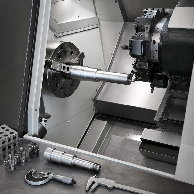
Quick answer: CNC turning center specifications describe what size, shape, material, accuracy, and features a lathe can produce. Important specs include chuck size, bar capacity, maximum turning diameter, turning length, spindle speed, turret tooling, live tooling, axes, and tolerance capability.

CNC Turning Center Specifications

A turning center is selected based on the part, not only on machine size. Shaft length, diameter, bore depth, thread type, groove position, live-milled features, material, and batch quantity all influence the best machine choice.

Key Points for Buyers and Engineers

Topic What to know Practical impact
Chuck size Workholding capacity for blanks Affects maximum part size.
Bar capacity Maximum bar diameter through spindle Important for production turned parts.
Turning length Maximum practical part length Controls shaft and sleeve feasibility.
Live tooling Milling/drilling tools on lathe Useful for cross holes, flats, and slots.
Axes X/Z plus C/Y or sub-spindle options Reduces secondary operations for complex parts.

How This Affects CNC Machined Parts

Turning centers are used for shafts, bushings, pins, sleeves, spacers, threaded parts, and round precision components. Review MTSPi’s CNC turning service for process fit.

Design and Purchasing Checklist

  • Provide maximum diameter and overall length.
  • Identify cross holes, flats, slots, and off-center features.
  • Confirm material, heat treatment, and finish.
  • Mark thread standards and inspection requirements.
  • Ask whether live tooling or secondary milling is needed.

Related MTSPi Resources

FAQ

What is a CNC turning center?

It is a CNC lathe that machines rotating workpieces and may include a turret, live tooling, sub-spindle, or additional axes.

What parts are made on turning centers?

Shafts, pins, bushings, sleeves, spacers, threaded fittings, and many round components.

What is live tooling?

Live tooling allows milling, drilling, or tapping operations on a turning center without moving the part to a separate mill.

Need help with CNC turning center part review?

Send drawings, material, quantity, finish, tolerance notes, and application requirements. MTSPi can review manufacturability before quoting.

Contact MTSPi for engineering and quote support

Practical Buyer Notes

Turning center specification pages should explain how machine specs affect real parts. Chuck size, bar capacity, turning length, spindle bore, turret stations, live tooling, and sub-spindle options all change what can be made efficiently.

Buyers usually do not need every machine parameter. They need to know whether their part diameter, length, material, thread, bore, cross holes, and tolerance fit the supplier’s turning capability.

How to Evaluate This Topic on a Real Drawing

Decision point Recommended approach Why it matters
Part diameter Check chuck size and turning diameter Determines whether the blank can be held and machined
Bar-fed production Check bar capacity Important for repeated small turned parts
Cross features Look for live tooling or secondary milling Reduces extra setups
Long shafts Review length, support, and runout control Prevents deflection and poor concentricity

Common Mistakes to Avoid

  • Selecting a turning supplier based only on maximum diameter.
  • Ignoring cross holes, flats, slots, and off-center features.
  • Forgetting to define thread standards and gauges.
  • Not discussing runout, concentricity, or surface finish for rotating parts.

Recommended MTSPi Review Workflow

MTSPi should review turned parts by diameter, length, material, features, tolerance, and quantity. This determines whether standard turning, Swiss-type machining, mill-turn, or secondary milling is best.

  1. Confirm the part function, operating environment, and assembly risk.
  2. Review material, process, tolerance, surface finish, and inspection requirements together.
  3. Separate critical features from general dimensions so cost is not wasted on non-functional details.
  4. Use related resources such as CNC materials, surface treatment, and quality assurance to complete the specification.
  5. Send the final drawing package to MTSPi for quote review before production.

What to Send for a Faster Quote

Send the drawing with diameter, length, bore, thread, groove, surface finish, material, quantity, and any runout or concentricity requirements.

  • 3D CAD file and 2D drawing with revision number.
  • Material grade or acceptable alternatives.
  • Quantity, delivery target, and whether samples are required first.
  • Critical dimensions, thread callouts, finish notes, and inspection requirements.
  • Application notes when the part is used in heat, moisture, wear, vibration, or visible assemblies.

Deeper Engineering Notes

For CNC turning center specifications, the strongest page is not just a definition. It should help a buyer decide what information belongs on the drawing, what questions to ask a supplier, and which details affect cost, quality, and delivery. In real RFQ work, the important details are usually bar capacity, chuck size, turning length, live tooling, sub-spindle use, runout, and concentricity. These details decide whether the supplier can quote confidently or has to return with repeated questions.

The common risk is ignoring cross holes, flats, slots, and secondary features when choosing a turning supplier. That risk can make the content look complete on the surface but weak in a real manufacturing situation. A stronger specification connects the topic to material behavior, machine access, tolerance control, finishing, and inspection before the order is released.

Example Specification Review

Review area Question to answer Good specification practice
Function What does this feature or part need to do? Describe the load, fit, motion, appearance, sealing, or assembly requirement.
Material Is the selected material suitable for the environment? Confirm strength, heat, corrosion, wear, chemical exposure, and cosmetic needs.
Geometry Can the feature be reached by standard tools? Review depth, corner radius, wall thickness, tool clearance, and setup direction.
Tolerance Which dimensions are truly critical? Use tight tolerances only where function requires them and keep general dimensions practical.
Verification How will acceptance be checked? Define gauges, CMM checks, roughness measurement, thread inspection, or visual standards when needed.

How This Page Should Support Ranking

This topic can attract both beginner searches and buyer searches. The beginner wants a clear answer; the buyer wants enough detail to make a manufacturing decision. A page has a better chance to rank when it answers the simple question first, then adds examples, process limits, design notes, comparison tables, and practical next steps.

That is also why internal links should be helpful rather than forced. A reader should naturally move from this page to a process page, material page, surface finish page, inspection page, or quote page only when that next step solves a real question.

Conclusion

Turning center specifications matter because they determine whether a part can be made efficiently in one setup. Clear drawings help the supplier choose the right turning route.

Categories
Blog CNC Materials Design, Cost & Sourcing

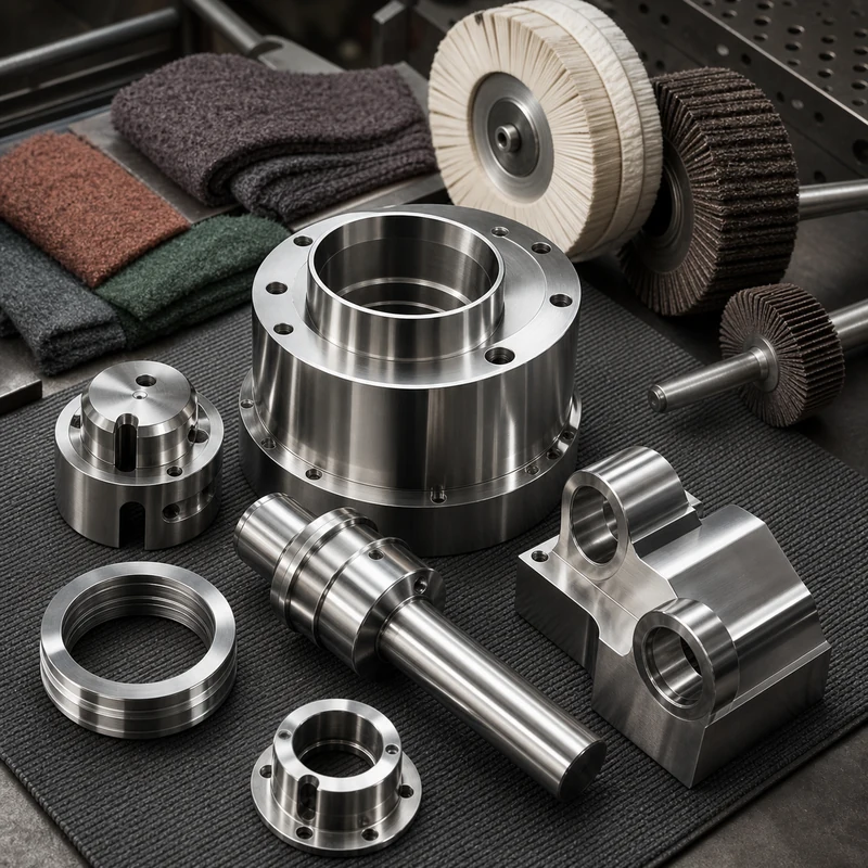
How to Polish Stainless Steel CNC Parts: Finishing Methods and Design Notes

Stainless steel CNC parts are polished to remove tool marks, improve appearance, reduce roughness, prepare for cleaning, or support corrosion-resistant service. The best method depends on the stainless grade, starting surface, part geometry, cosmetic expectations, and whether the finish is decorative, functional, or both.

Polishing should be planned before production rather than treated as a last-minute cosmetic step. MTSPi can combine stainless steel CNC machining, surface finish planning, and quality checks so machined features and finished surfaces match the drawing intent.

Why Polish Stainless Steel Parts?

  • Remove visible cutter marks, burr traces, scratches, or handling marks.
  • Create a brushed, satin, bright, or mirror-like appearance.
  • Reduce surface roughness where cleaning, sealing, or flow behavior matters.
  • Improve corrosion performance when polishing is paired with proper cleaning or passivation.
  • Prepare selected surfaces for assembly, inspection, or customer-facing use.

Common Polishing Methods

Method Typical Result Best Use
Deburring and edge blending Safer edges and cleaner transitions General machined parts before cosmetic finishing
Abrasive grinding Removes deeper tool marks and uneven areas Pre-polish correction or weld/stock cleanup
Brushing Uniform directional satin texture Panels, covers, brackets, visible housings
Buffing Bright reflective surface Decorative components and customer-facing hardware
Mirror polishing Very high reflectivity after staged abrasives Optical, medical, food, and premium cosmetic surfaces
Electropolishing Electrochemical smoothing and cleaning Complex stainless parts, hygienic surfaces, and corrosion-sensitive applications

A Practical Stainless Steel Polishing Workflow

1. Define the target finish

The finish should be described with a surface roughness value, visual standard, grain direction, sample photo, or approved reference part. Terms like “nice polish” or “shiny” are too vague for repeat production.

2. Machine with finishing allowance in mind

Polishing removes material. If a critical diameter, sealing surface, or flatness callout will be polished, the machining plan may need allowance and inspection after finishing. Tight features should not be polished aggressively unless the drawing accounts for it.

3. Remove defects gradually

Deep scratches, heavy cutter marks, and sharp edges should be reduced with controlled abrasives before fine polishing. Jumping directly to a fine compound can leave hidden waves, dull patches, or inconsistent reflections.

4. Clean and protect the part

After polishing, stainless steel parts should be cleaned to remove abrasive residue, compounds, oils, and loose particles. Depending on the application, passivation or electropolishing may be specified to improve surface cleanliness and corrosion behavior.

Stainless Steel Grades and Finish Behavior

Grade Family Polishing Notes Typical CNC Use
304 stainless steel Polishes well and is widely used for general corrosion resistance Housings, brackets, food equipment, covers
316 stainless steel Good corrosion resistance and common in harsher environments Medical, marine, chemical, and hygienic components
17-4 PH stainless steel Can be heat treated; finish planning should account for hardness condition High-strength shafts, fixtures, aerospace and industrial parts
303 stainless steel Machines well, but corrosion and finishing expectations should be checked Turned parts, fittings, fasteners, bushings

Design Notes Before Specifying a Polish

  • Avoid deep narrow pockets if the inside surfaces must be cosmetically polished.
  • Mark which faces are cosmetic and which are non-visible functional surfaces.
  • Specify grain direction for brushed finishes on panels or covers.
  • Confirm whether threaded holes, sharp edges, datums, and bores must be protected during finishing.
  • Define inspection after finishing when surface removal could affect tolerances.

Polishing vs Passivation vs Electropolishing

Mechanical polishing changes texture and appearance by physically smoothing the surface. Passivation chemically removes free iron and supports corrosion resistance. Electropolishing removes a thin surface layer electrochemically, which can smooth micro-peaks and improve cleanliness on suitable stainless parts. These processes can be combined, but they are not interchangeable.

Process Main Purpose Changes Dimensions?
Mechanical polishing Appearance and roughness control Yes, depending on abrasive stage and pressure
Passivation Surface chemistry and corrosion support Minimal dimensional change
Electropolishing Micro-smoothing, cleaning, and corrosion support Small controlled material removal

How MTSPi Supports Stainless Finishing

For stainless components, MTSPi reviews machining, polishing access, tolerance risk, edge requirements, cleaning, and inspection before production. Send your 3D model, drawing, stainless grade, target finish, cosmetic faces, and quantity through our RFQ channel.

Related MTSPi Resources

FAQ

Can all stainless steel CNC parts be mirror polished?

Not always. Mirror polishing depends on grade, geometry, access, starting surface, tolerance limits, and cost. Some internal features are impractical to polish uniformly.

Does polishing improve corrosion resistance?

A smoother and cleaner surface can help, but corrosion performance also depends on stainless grade, contamination control, passivation, environment, and maintenance.

Categories
Blog Design, Cost & Sourcing Machine Tools & Programming

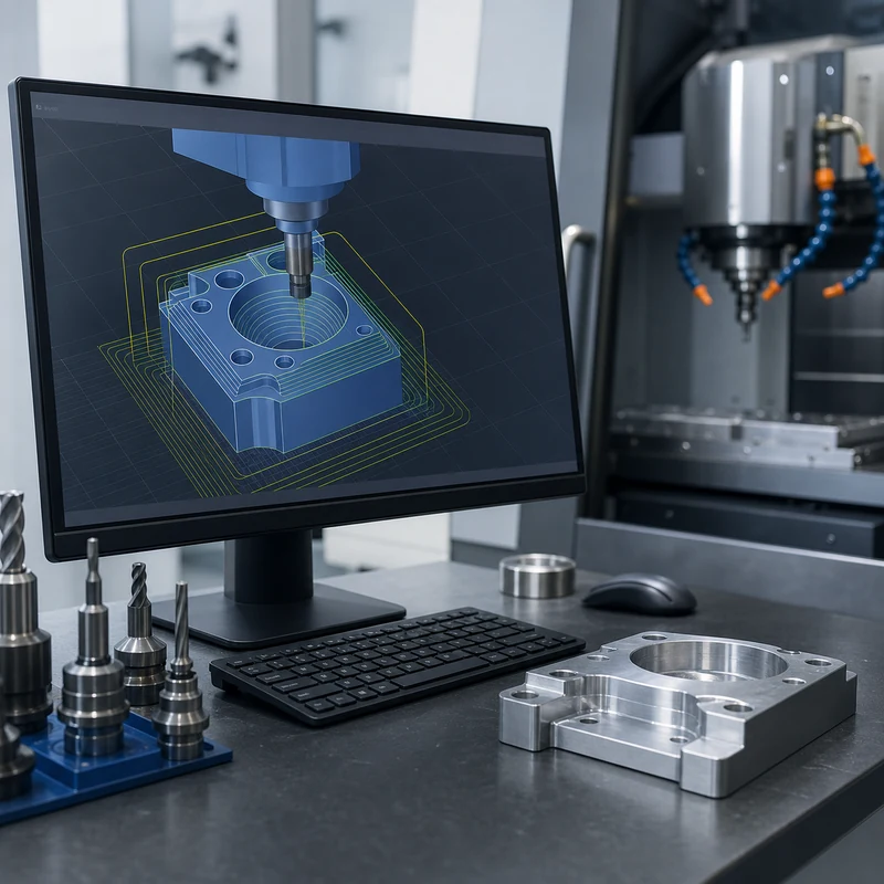
How CNC Machining Software Improves Production Efficiency

CNC machining software improves production efficiency by turning a CAD model into controlled toolpaths, repeatable setup instructions, reliable simulations, and measurable process data. Good software does not replace skilled machinists, but it gives programmers and production teams better ways to reduce waste, avoid collisions, shorten setup time, and standardize repeat jobs.

For custom parts, the software workflow matters as much as the machine itself. MTSPi uses digital review, programming, process planning, and quality assurance methods to connect design intent with real machining results.

Where CNC Software Fits in Production

Stage Software Role Efficiency Benefit
Design review Checks geometry, manufacturability, access, and missing drawing details Reduces quoting surprises and redesign loops
CAM programming Creates roughing, finishing, drilling, tapping, and contouring toolpaths Shortens programming time and standardizes best practices
Simulation Tests tool reach, holder clearance, stock removal, and machine motion Prevents crashes and wasted setups
Setup planning Defines fixtures, work offsets, tools, and operation sequence Reduces spindle idle time and operator confusion
Inspection feedback Connects measured results to process adjustments Improves repeatability across batches

Key Ways Software Improves Efficiency

Faster programming

Modern CAM systems let programmers reuse templates, tool libraries, feeds, speeds, machining strategies, and post-processors. This is especially useful when similar materials, hole patterns, pockets, or part families appear across multiple projects.

Better toolpath quality

Adaptive roughing, rest machining, high-speed finishing, and optimized entry moves can reduce cycle time while protecting cutters and workpieces. The goal is not simply to move faster; it is to keep tool engagement predictable and finish quality consistent.

Fewer setup errors

Digital setup sheets help operators understand stock size, vise orientation, fixture location, work offsets, tool numbers, inspection checks, and special notes. Clear setup information reduces avoidable mistakes during first article and repeat production.

Safer complex machining

For 5-axis machining, simulation is essential. Software helps verify rotary motion, toolholder clearance, machine limits, and approach angles before material is cut.

Software Does Not Eliminate Process Judgment

Efficient CNC production still depends on material behavior, tool condition, coolant, workholding rigidity, machine capability, inspection planning, and operator feedback. Software can suggest a path, but experienced manufacturing teams decide whether that path is stable, economical, and measurable.

Common Software Capabilities

  • CAD model import and geometry repair for machining preparation.
  • Tool library management with cutter length, diameter, holder, and material-specific data.
  • Automatic and manual toolpath generation for milling, turning, drilling, tapping, and finishing.
  • Collision checking between tool, holder, fixture, stock, and machine components.
  • Post-processing that outputs machine-specific CNC code.
  • Setup sheets and inspection plans for repeatable shop-floor execution.

Benefits for Buyers

Buyers may not see the CAM file, but they feel the result through quoting clarity, shorter lead times, consistent repeat orders, fewer part revisions, and better communication about difficult features. If a part has deep pockets, thin walls, tight bores, complex curves, or multiple setups, software-backed planning can make the difference between an unstable process and a controlled one.

Design Data That Helps Software Work Better

  • Send native 3D CAD when available, plus STEP files for neutral exchange.
  • Include a 2D drawing for threads, tolerances, surface finish, critical datums, and inspection notes.
  • Define material grade, quantity, finish, and application requirements.
  • Flag cosmetic surfaces and assembly interfaces before programming starts.
  • Tell the manufacturer whether prototype speed or production repeatability is the priority.

Related MTSPi Resources

FAQ

Is CAD the same as CAM?

No. CAD is used to create or modify the part model. CAM uses that model to generate machining toolpaths and CNC programs.

Can software reduce CNC machining cost?

Often, yes. Better toolpaths, fewer setups, reduced scrap, reusable templates, and clearer setup sheets can lower the total manufacturing effort.

Request A Quote

We'll Send You Back with Price Immediately!

DEC 1-31

XMAS SPECEIL

Up to

40% off

How CNC Machining Software Improves Production Efficiency

We'll Send You Back with Price Immediately!