Categories
Blog Industries & Applications Quality & Tolerances

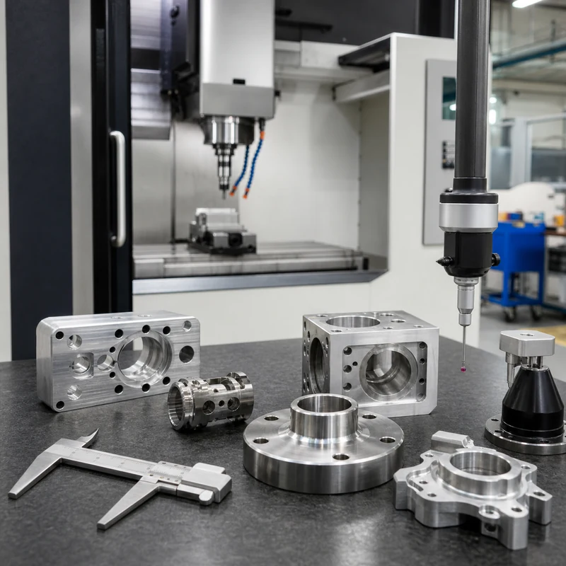
How to Evaluate CNC Machining Companies in India in 2026

India is an important manufacturing market for buyers who need CNC machined parts, precision assemblies, prototypes, and repeat production support. The right supplier can shorten development cycles and reduce sourcing risk, but a country-level search is only a starting point. Engineering teams still need to verify process capability, material control, inspection discipline, communication quality, and delivery reliability.

This MTSPi guide explains how to evaluate CNC machining companies in India without relying on a simple brand list. It focuses on practical buying criteria for custom components in aerospace, automotive, medical, robotics, electronics, and industrial equipment. MTSPi can also review drawings through its CNC machining services workflow when a project needs an alternate sourcing path.

Why Buyers Look at India for CNC Machining

India has a large manufacturing base with strengths in automotive components, industrial equipment, aerospace supply chains, defense-related manufacturing, electronics, and engineering services. Several regional hubs have developed strong machining ecosystems with access to skilled labor, tooling suppliers, and export-oriented production experience.

For buyers, the appeal is a combination of engineering talent, competitive manufacturing cost, and growing experience with global quality expectations. The practical challenge is variation between suppliers: machine capability, inspection culture, finishing partners, and communication habits can differ significantly.

Supplier Evaluation Checklist

Evaluation Area What to Confirm Why It Matters
Process fit 3-axis milling, 4-axis indexing, 5-axis machining, CNC turning, mill-turn, EDM, grinding, or Swiss-type capability The equipment and setup strategy must match the actual geometry
Material experience Aluminum, stainless steel, tool steel, titanium, brass, copper, and engineering plastics Material behavior affects tolerance, burrs, tool wear, finish, and lead time
Quality planning CMM inspection, calibrated gauges, first-article reports, in-process checks, and revision control Precision parts need measurable evidence, not only visual approval
Production range Prototype, low-volume, bridge production, and repeat-batch support A strong sample must translate into stable repeat orders
Finishing control Anodizing, passivation, plating, bead blasting, polishing, heat treatment, and packaging Post-processing can change dimensions, appearance, and delivery risk
Communication DFM feedback, drawing questions, response time, English documentation, and change tracking Clear technical communication prevents rework

Match the Supplier to the Part Type

A supplier that is excellent for simple brackets may not be the best choice for a thin-wall housing, a tight-concentricity shaft, a cosmetic aluminum enclosure, or a 5-axis aerospace-style component. Build the shortlist around the part, not around the marketing category.

Part Requirement Supplier Capability to Look For Inspection Focus
Complex multi-face geometry 5-axis machining or reliable multi-setup fixture planning Datum relationships, profile tolerance, and repeat setup error
Turned shafts and sleeves CNC turning, mill-turn, or Swiss-type machining Diameter, runout, concentricity, thread quality, and surface finish
Cosmetic enclosures Stable aluminum milling plus finishing coordination Visible surfaces, edge breaks, anodizing allowance, and packaging
Medical or aerospace-style parts Controlled processes, material records, and documented inspection Critical dimensions, traceability, CMM data, and nonconformance handling
Production batches Fixture control, tool-life rules, and repeatable process documentation Lot-to-lot consistency and sampling plan

Quality Questions to Ask Before Placing an Order

  • Which dimensions are highest risk, and how will they be measured?
  • How many setups are planned, and how will datum transfer be controlled?
  • Will inspection be performed before or after surface treatment?
  • Can the supplier provide a sample inspection report for similar tolerances?
  • How are material certificates, drawing revisions, and process changes controlled?
  • What packaging method protects cosmetic surfaces and precision edges during shipment?

Cost, Lead Time, and Hidden Risk

Unit price is only one part of sourcing cost. Buyers should also account for material availability, fixture cost, programming effort, inspection time, finishing lead time, export paperwork, logistics, and the cost of rework if requirements are misunderstood. A quote that ignores tolerance, finish, inspection, or packaging assumptions is not complete.

For Asia-based sourcing, compare landed cost and project control rather than machine-hour pricing alone. Customs timing, finishing coordination, drawing clarification, and inspection documentation can matter as much as the quoted unit price.

When MTSPi Can Be a Practical Alternative

MTSPi supports custom CNC machining projects that need engineering review, competitive production cost, broad material options, finishing coordination, and inspection documentation. Services include CNC milling, CNC turning, 5-axis CNC machining, prototype machining, and low-volume production. For material selection, review the CNC materials library.

RFQ Package for Accurate Supplier Comparison

RFQ Item Recommended Detail
3D CAD model STEP or equivalent neutral file
2D drawing Tolerances, GD&T, threads, surface finish, datums, and critical notes
Material Grade, temper, standard, and certificate requirement
Finish Process, color, thickness, cosmetic surfaces, and masking notes
Quantity Prototype quantity, annual volume, release schedule, and repeat order expectations
Inspection Critical dimensions, report format, sampling level, and CMM needs

Related MTSPi Resources

FAQ

How should I compare CNC machining companies in India?

Compare suppliers by part fit, machine capability, material experience, tolerance control, inspection method, communication, finishing support, and repeat-production reliability.

Should I choose the lowest CNC machining quote?

Not automatically. A low quote can be useful, but it should include the same material, tolerance, finish, inspection, lead-time, and packaging assumptions as the competing quotes.

What files should I send for a CNC machining quote?

Send a 3D CAD file, a 2D drawing, material grade, finish requirements, quantity, target lead time, inspection requirements, and notes on the features that matter most to function.
Categories
Blog Industries & Applications Quality & Tolerances

How to Evaluate CNC Machining Companies in the UK in 2026

The UK has a deep precision engineering base, and buyers can find strong CNC machining suppliers for aerospace, medical, automotive, energy, electronics, defense, and industrial equipment. The challenge is not finding a machine shop; it is choosing one that fits the part, documentation level, quality risk, and production volume.

This guide gives procurement and engineering teams a practical way to evaluate CNC machining companies in the UK in 2026. It avoids a brand-by-brand ranking and focuses on the selection criteria that actually affect custom machined parts: process capability, inspection discipline, material experience, communication, and delivery control. If you are comparing local sourcing with overseas production, MTSPi can also review drawings through its CNC machining services workflow.

Quick Evaluation Checklist

Evaluation Area What to Check Why It Matters
Part fit Examples of similar components, sizes, tolerances, finishes, and batch quantities Relevant experience reduces setup risk
Machine capability 3-axis milling, 4-axis indexing, 5-axis machining, CNC turning, mill-turn, Swiss-type machining, EDM The process must match the geometry, not just the RFQ keyword
Material experience Aluminum, stainless steel, tool steel, titanium, brass, copper, engineering plastics Material behavior affects accuracy, burrs, cycle time, and finish
Quality system CMM inspection, calibrated gauges, first-article reports, ISO or sector-specific controls Critical parts need measurable evidence
Communication DFM feedback, revision tracking, drawing questions, clear lead-time assumptions Good communication prevents expensive rework
Scalability Prototype support, low-volume production, repeat-batch control, packaging, supplier coordination A good sample must translate into reliable production

Start With Your Part Requirements

A good supplier shortlist starts with the drawing, CAD model, material, quantity, target lead time, finish, tolerance class, and inspection expectations. A simple aluminum plate, a stainless shaft, a medical housing, and a 5-axis aerospace bracket require different equipment, setups, inspection tools, and supplier habits.

  • For tight datum relationships, ask how many setups are planned and how the datums will be protected.
  • For cosmetic parts, define finish direction, visible surfaces, edge breaks, and packaging requirements.
  • For prototype parts, check whether the supplier can provide DFM feedback before cutting metal.
  • For repeat production, ask about fixture control, tool-life rules, and lot-to-lot inspection records.

Machining Processes to Compare

Process Best Fit Questions to Ask
3-axis CNC milling Plates, brackets, pockets, covers, prismatic components Can critical sides be held in one setup or will datum transfer be needed?
4-axis machining Multi-side features, radial holes, indexed operations Is the rotary setup stable enough for the tolerance stack?
5-axis machining Complex housings, angled features, undercuts, high-value parts Will it reduce setups or only add cost?
CNC turning Shafts, bushings, spacers, threaded parts, round components How are concentricity, bore size, and face runout checked?
Mill-turn machining Turned parts with milled flats, holes, slots, or cross features Can one handling reduce alignment error?
EDM Sharp internal corners, hard materials, fine slots, tooling features Is EDM needed for function or only for convenience?

Quality and Certification Checks

Certifications can be useful, but they are not a substitute for part-specific quality planning. Ask how the supplier will inspect your actual drawing. For many projects, a practical plan includes in-process checks, final inspection, CMM data for complex geometry, gauge records for threads and bores, and a clear nonconformance process. MTSPi provides similar planning through quality assurance support for custom parts.

  • Request a sample inspection report before approving a critical production order.
  • Confirm whether dimensions apply before or after anodizing, plating, passivation, or polishing.
  • Ask how measurement uncertainty is managed for very tight tolerances.
  • Check whether drawing revisions are controlled across quotation, programming, inspection, and shipment.

Materials and Finishes

UK suppliers often support common production materials, but availability, cost, and lead time vary. For international projects, compare material procurement, certificates, finishing partners, and dimensional allowance after finishing. MTSPi maintains a practical CNC materials library for reviewing material choices before quotation.

Requirement Useful Buyer Question Risk If Ignored
Aluminum parts Which alloy and temper are required? Unexpected movement, finish mismatch, or strength concerns
Stainless parts How will burrs, work hardening, and surface finish be controlled? Tool wear, poor finish, or edge damage
Titanium parts Does the supplier have stable tooling and heat-control experience? High cost, distortion, or poor repeatability
Plastic parts How will clamping marks, stress, and thermal movement be managed? Warping or out-of-tolerance features
Surface treatment Which dimensions are critical after finish? Assembly problems or cosmetic rejection

When a UK Supplier Makes Sense

A UK CNC machining company may be the best fit when engineering communication, fast design iteration, regulated documentation, local logistics, or close project coordination matter more than unit price alone. For urgent prototypes or sensitive programs, proximity can reduce communication delay and simplify supplier visits.

When to Consider MTSPi as an Alternative

For buyers who need custom machined parts with competitive production cost, engineering review, broad material support, and documented inspection, MTSPi can provide another sourcing option. We support CNC milling, CNC turning, multi-axis machining, prototype machining, low-volume production, finishing, and inspection reporting.

Red Flags During Supplier Selection

  • The quote does not mention tolerance, finish, inspection, or material assumptions.
  • The supplier accepts every requirement without asking technical questions.
  • Lead time excludes finishing, inspection, or material procurement.
  • The supplier cannot explain fixturing or datum control for critical features.
  • Communication is slow before the order; it rarely improves after the order is placed.

Related MTSPi Resources

FAQ

How should I compare CNC machining companies in the UK?

Compare suppliers by part similarity, machine capability, material experience, inspection method, documentation quality, communication, lead-time realism, and repeat-production control.

Is the closest CNC machine shop always the best choice?

No. Location helps communication and logistics, but the best supplier is the one whose equipment, process planning, and quality system fit the specific part requirements.

What files should I send for an accurate CNC machining quote?

Send 3D CAD, a 2D drawing with tolerances and GD&T, material grade, finish, quantity, inspection requirements, and any functional notes that affect critical features.

Categories
Blog CNC Machining Basics Quality & Tolerances

What Is a Micrometer? Precision Measurement for CNC Machined Parts

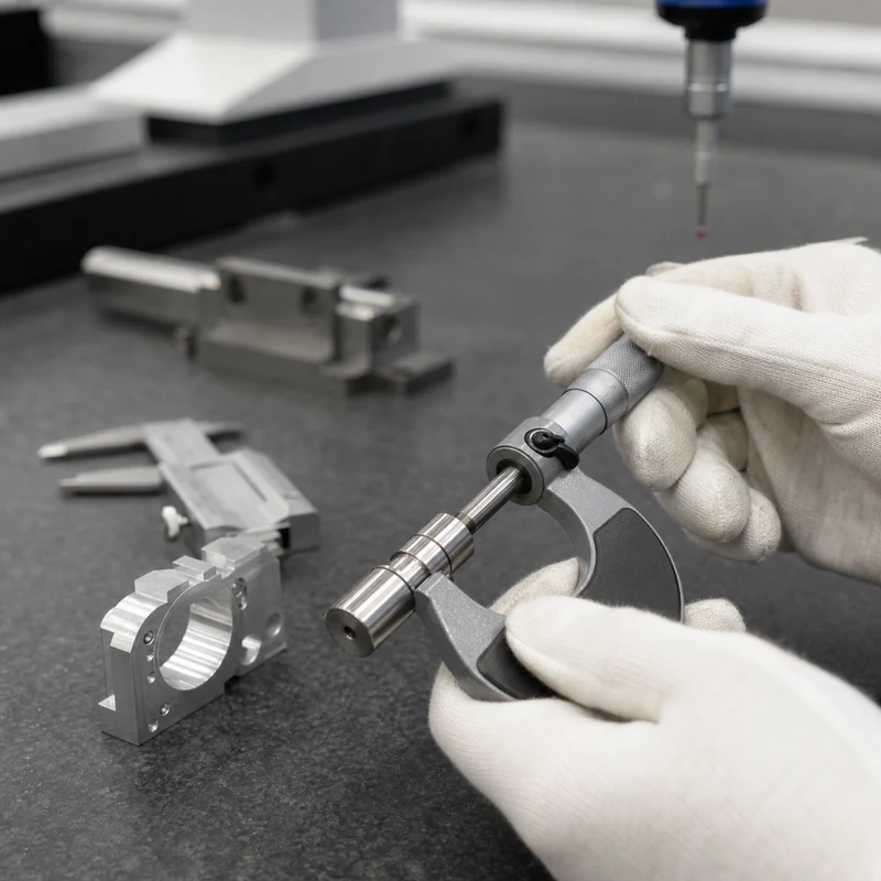
A micrometer is a precision measuring tool used to check small dimensions such as outside diameter, thickness, step height, groove width, and depth. In CNC machining, it is often used for fast, repeatable checks on features that need tighter control than a basic ruler or many general-purpose caliper checks can provide.

Micrometers are important because CNC parts are judged by measurable dimensions, not appearance alone. A shaft may look correct but still fail if its diameter, roundness, or fit tolerance is outside the drawing requirement. MTSPi combines micrometer checks with CNC machining quality inspection, CMM inspection, gauges, and documented quality procedures.

How a Micrometer Works

Most micrometers use a precision screw mechanism. As the thimble turns, the spindle moves toward or away from the anvil by a known distance. The part is placed between the anvil and spindle, and the scale or digital display shows the measured dimension.

Part of the Micrometer Function Inspection Note
Frame Holds the anvil and spindle in alignment A rigid frame helps reduce measurement error
Anvil Fixed measuring face Must be clean and free of burrs
Spindle Moving measuring face Should contact the part with controlled force
Sleeve and thimble Mechanical scale used to read the measurement Requires correct reading technique
Ratchet or friction stop Applies consistent measuring pressure Helps different inspectors get similar results
Lock Holds the spindle position Useful when recording or comparing a reading

Common Types of Micrometers

Micrometer Type Typical Use Example CNC Part Feature
Outside micrometer External diameters and thicknesses Turned shafts, plates, bosses, spacers
Inside micrometer Internal widths and larger bore sizes Housings, slots, internal steps
Depth micrometer Depths of holes, pockets, grooves, and shoulders Milled pockets and blind holes
Blade micrometer Narrow grooves and recessed features Thin slots or retaining-ring grooves
Point micrometer Small grooves or difficult contact areas Fine turned details
Digital micrometer Fast reading and data capture Production inspection and operator checks

Micrometer Accuracy and Resolution

A micrometer is commonly available with fine resolution, but resolution is not the same as total measurement accuracy. Accuracy depends on calibration, operator technique, temperature, tool condition, part cleanliness, and whether the measuring faces contact the intended feature correctly.

  • A clean measuring surface prevents chips or oil from creating a false reading.
  • Consistent ratchet force reduces operator-to-operator variation.
  • Temperature matters because both the part and the tool can expand or contract.
  • Calibration records are needed when measurements support formal quality documentation.

How Micrometers Are Used in CNC Machining

Machinists and inspectors often use micrometers at three stages: incoming material checks, in-process checks, and final inspection. The tool is fast enough for shop-floor use but precise enough to help control critical dimensions.

Incoming Material Checks

Before machining starts, a micrometer can verify bar diameter, plate thickness, stock condition, or pre-machined blanks. This prevents a job from starting with material that cannot clean up to the final dimension.

In-Process Inspection

During machining, micrometers help operators confirm whether tool wear, thermal drift, offsets, or workholding movement are affecting critical features. Early checks reduce scrap because corrections can be made before the entire batch is finished.

Final Inspection

After machining, micrometer measurements may be recorded with other inspection results. For complex geometry, micrometers are usually paired with CMM inspection, bore gauges, thread gauges, height gauges, surface roughness checks, or functional gauges.

Micrometer vs Caliper

Tool Strength Limitation
Micrometer Higher repeatability for specific external, internal, or depth measurements Less versatile; each type covers a narrower measurement range
Caliper Fast general measurements across many feature types Usually less repeatable for very tight tolerances

A caliper is useful for quick checks and general dimensions. A micrometer is preferred when the feature has tighter tolerance, when repeatability matters, or when the contact geometry of the tool better matches the measured feature.

Best Practices for Reliable Micrometer Readings

  • Clean the part and measuring faces before every critical reading.
  • Use the ratchet or friction stop instead of squeezing the part by hand pressure.
  • Measure at multiple positions when checking round parts for taper or out-of-round conditions.
  • Let precision parts stabilize near inspection temperature before final measurement.
  • Store micrometers in a clean case and keep calibration records current.
  • Use the correct micrometer type and range for the feature being inspected.

Where Micrometers Fit in a Quality System

Micrometers are only one part of a complete inspection plan. MTSPi uses them alongside calipers, CMM inspection, thread gauges, pin gauges, visual checks, surface finish checks, and documented process controls. The right inspection method depends on the feature function, tolerance, drawing requirement, and production risk. Learn more on our quality assurance page.

Typical CNC Features Checked With Micrometers

Feature Common Tool What to Watch
Shaft diameter Outside micrometer Check several positions for taper or ovality
Plate thickness Outside micrometer Avoid chips, burrs, and clamping marks
Groove depth Depth or blade micrometer Confirm contact surfaces match the drawing reference
Small step height Depth micrometer Verify datum surface cleanliness
Bore-related features Inside micrometer or bore gauge Confirm the tool is suitable for the bore size and tolerance

How MTSPi Controls Precision Measurements

For custom CNC machining projects, MTSPi reviews the drawing before production to identify critical dimensions, inspection methods, and reporting needs. For tight tolerance parts, we combine stable machining processes with in-process checks and final inspection records. Related services include CNC milling, CNC turning, 5-axis machining, and surface treatment.

Related MTSPi Resources

FAQ

What is a micrometer used for in CNC machining?

A micrometer is used to measure critical dimensions such as shaft diameters, part thicknesses, step heights, grooves, and other features that require repeatable precision checks.

Is a micrometer more accurate than a caliper?

For many tight-tolerance features, yes. A micrometer usually provides better repeatability for a specific measurement, while a caliper is more versatile for general checking.

How often should a micrometer be calibrated?

Calibration frequency depends on usage, required accuracy, quality procedures, and inspection risk. In professional machining environments, micrometers should be checked and calibrated on a defined schedule.

Categories
Blog CNC Materials Industries & Applications Quality & Tolerances

CNC Machining for Medical Devices: Materials, Applications, and Quality Checks

Quick answer: CNC machining is used for medical device prototypes, surgical tools, instrument parts, housings, fixtures, test components, and precision hardware. Medical parts often require careful material selection, clean machining, dimensional inspection, traceability, and clear documentation.

CNC Machining for Medical Devices

Medical machining is not only about tight tolerances. Buyers must consider biocompatible or application-appropriate materials, clean edges, surface finish, inspection records, and consistent communication about critical features.

Key Points for Buyers and Engineers

Topic What to know Practical impact
Materials Stainless steel, titanium, aluminum, PEEK, PC, PPSU Material must match use and regulatory expectations.
Features Small holes, slots, threads, mating surfaces Tool access and burr control are important.
Inspection CMM, gauges, visual checks, reports Confirms critical dimensions and drawing requirements.
Finish Polishing, passivation-like cleaning, anodizing, marking Affects appearance, corrosion behavior, and cleanliness.

How This Affects CNC Machined Parts

Medical prototypes may use both milling and turning. The process should be selected by geometry, material, tolerance, surface finish, and inspection requirements rather than by price alone.

Design and Purchasing Checklist

  • Mark critical dimensions and datums clearly.
  • Confirm material grade and certificate needs.
  • Define burr, edge break, and cleanliness expectations.
  • Request inspection reports when fit is critical.
  • Review finish compatibility before production.

Related MTSPi Resources

FAQ

What medical parts can be CNC machined?

Instrument components, housings, fixtures, prototype parts, surgical tool components, and precision hardware can be machined.

Is titanium used for medical CNC parts?

Yes, titanium is used in certain medical applications because of strength, corrosion resistance, and biocompatibility considerations.

Do medical CNC parts need CMM inspection?

Many precision medical parts benefit from CMM inspection, especially when GD&T or assembly-critical features are present.

Need help with medical CNC machining?

Send drawings, material, quantity, finish, tolerance notes, and application requirements. MTSPi can review manufacturability before quoting.

Contact MTSPi for engineering and quote support

Practical Buyer Notes

Medical machining pages need depth because the topic involves more than precision. Cleanliness, burr control, traceability, material documentation, surface finish, and inspection expectations can all be important.

The page should avoid making regulatory claims that are too broad. Instead, it should explain practical manufacturing controls for prototypes, test fixtures, instruments, housings, and precision medical hardware.

How to Evaluate This Topic on a Real Drawing

Decision point Recommended approach Why it matters
Material Confirm stainless steel, titanium, PEEK, PC, or other grade Material must match function and documentation needs
Burr control Define edge breaks and clean transitions Sharp edges can create safety and assembly issues
Inspection Use CMM, gauges, and reports for critical features Supports part verification
Cleanliness Plan cleaning and packaging expectations Protects parts during handling and shipment

Common Mistakes to Avoid

  • Using vague material names instead of exact grades.
  • Ignoring burrs on small holes, slots, and edges.
  • Treating surface finish as cosmetic only.
  • Failing to define inspection records before production.

Recommended MTSPi Review Workflow

MTSPi should review medical-related CNC parts with extra attention to material, edge condition, finish, and critical dimensions. The page should explain this clearly without overstating certification scope.

  1. Confirm the part function, operating environment, and assembly risk.
  2. Review material, process, tolerance, surface finish, and inspection requirements together.
  3. Separate critical features from general dimensions so cost is not wasted on non-functional details.
  4. Use related resources such as CNC materials, surface treatment, and quality assurance to complete the specification.
  5. Send the final drawing package to MTSPi for quote review before production.

What to Send for a Faster Quote

Send CAD, drawing, material grade, finish, required reports, cleaning expectations, critical dimensions, and whether the part is for prototype, fixture, or production use.

  • 3D CAD file and 2D drawing with revision number.
  • Material grade or acceptable alternatives.
  • Quantity, delivery target, and whether samples are required first.
  • Critical dimensions, thread callouts, finish notes, and inspection requirements.
  • Application notes when the part is used in heat, moisture, wear, vibration, or visible assemblies.

Deeper Engineering Notes

For medical CNC machining, the strongest page is not just a definition. It should help a buyer decide what information belongs on the drawing, what questions to ask a supplier, and which details affect cost, quality, and delivery. In real RFQ work, the important details are usually material traceability, burr control, clean handling, inspection reports, and revision discipline. These details decide whether the supplier can quote confidently or has to return with repeated questions.

The common risk is making broad claims without defining the exact medical application and documentation needs. That risk can make the content look complete on the surface but weak in a real manufacturing situation. A stronger specification connects the topic to material behavior, machine access, tolerance control, finishing, and inspection before the order is released.

Example Specification Review

Review area Question to answer Good specification practice
Function What does this feature or part need to do? Describe the load, fit, motion, appearance, sealing, or assembly requirement.
Material Is the selected material suitable for the environment? Confirm strength, heat, corrosion, wear, chemical exposure, and cosmetic needs.
Geometry Can the feature be reached by standard tools? Review depth, corner radius, wall thickness, tool clearance, and setup direction.
Tolerance Which dimensions are truly critical? Use tight tolerances only where function requires them and keep general dimensions practical.
Verification How will acceptance be checked? Define gauges, CMM checks, roughness measurement, thread inspection, or visual standards when needed.

How This Page Should Support Ranking

This topic can attract both beginner searches and buyer searches. The beginner wants a clear answer; the buyer wants enough detail to make a manufacturing decision. A page has a better chance to rank when it answers the simple question first, then adds examples, process limits, design notes, comparison tables, and practical next steps.

That is also why internal links should be helpful rather than forced. A reader should naturally move from this page to a process page, material page, surface finish page, inspection page, or quote page only when that next step solves a real question.

Conclusion

CNC machining can support medical device development when material, cleanliness, tolerance, finish, and inspection expectations are defined clearly from the start.

Categories
Blog Quality & Tolerances Surface Finishing

AI in CNC Machining: Practical Applications, Limits, and Future Trends

Artificial intelligence is becoming useful in CNC machining, but its role is practical rather than magical. It can help engineers analyze data, improve programming decisions, detect process drift, organize production schedules, and support inspection. It does not remove the need for capable machines, experienced programmers, stable fixtures, or sound manufacturing judgment.

For custom machined parts, the strongest results come when AI tools are connected to real process knowledge: material behavior, tool access, tolerance risk, machine condition, and inspection data. MTSPi treats AI as a support layer inside disciplined CNC machining services, not as a substitute for engineering review.

Where AI Fits in CNC Machining

Application What AI Can Support Human Control Still Needed
Programming support Feature recognition, operation suggestions, setup notes, coding assistance Datum strategy, tool selection, fixture review, collision judgment
Toolpath optimization Parameter suggestions, engagement analysis, cycle-time comparison Material behavior, machine limits, surface-finish requirements
Predictive maintenance Trend detection from vibration, load, temperature, and spindle data Maintenance decisions and production scheduling
Quality inspection Vision checks, defect classification, measurement trend analysis Gauge selection, CMM programming, drawing interpretation
Production planning Capacity analysis, job sequencing, bottleneck visibility Priority decisions, supplier coordination, customer commitments

AI-Assisted CNC Programming

Programming complex parts requires decisions about workholding, tool reach, cutting sequence, rest machining, collision avoidance, and finishing strategy. AI-supported software can help recognize features, compare operation choices, and reduce repetitive programming work. The final program still needs review by someone who understands the machine, tools, material, and tolerance plan.

  • Shorter programming time for repeated feature families.
  • Earlier warnings about tool access or collision risk.
  • More consistent operation templates across similar parts.
  • Better knowledge capture from historical machining jobs.

Toolpath Optimization and Cutting Data

AI systems can analyze previous jobs, material data, tool performance, and machine load to recommend changes to feeds, speeds, stepovers, depth of cut, and cutting sequence. This can be valuable for 5-axis machining, titanium machining, stainless steel parts, and high-mix low-volume production where process setup time matters.

Goal AI Contribution Practical Check
Reduce cycle time Compare tool engagement and air-cutting time Do not sacrifice surface finish or tool life
Improve tool life Identify load spikes and unstable cutting zones Confirm with real tool wear data
Stabilize dimensions Track drift and suggest compensation windows Use measurement feedback from critical features
Improve finish Correlate parameters with roughness or visible marks Validate with surface roughness inspection when required

Predictive Maintenance

Unexpected machine downtime can disrupt delivery and create quality risk. Predictive systems use sensor data such as vibration, spindle load, temperature, servo behavior, and alarm history to flag abnormal trends before a failure stops production. For precision machining, this matters because worn spindles, thermal drift, or unstable axes can affect accuracy long before a machine completely fails.

AI and Automated Inspection

Inspection is one of the most practical AI use cases. Camera systems can help detect surface defects, missing features, burrs, mixed parts, or handling damage. Measurement data can also be analyzed over time to identify tool wear, fixture movement, or process drift. However, AI inspection must be tied to the drawing and validated measurement methods.

  • Use CMM inspection for GD&T, datums, and complex feature relationships.
  • Use micrometers, bore gauges, thread gauges, and pin gauges where they match the feature function.
  • Use camera inspection for visible defects, part presence, orientation, and surface anomalies.
  • Use trend analysis to catch process movement before parts go out of tolerance.

Production Planning and Scheduling

A CNC shop must balance machine availability, materials, tool setup, fixture use, inspection capacity, finishing lead times, and customer priorities. AI-driven planning tools can highlight bottlenecks and propose job sequences, but they work best when the underlying data is accurate and the team updates real constraints such as material arrival, urgent rework, or inspection queue delays.

Limits of AI in CNC Manufacturing

AI can support better decisions, but it cannot guarantee part quality by itself. Poor drawings, vague tolerances, weak fixtures, worn tools, unverified material, or incomplete inspection plans will still create problems. The most reliable approach combines software, skilled engineers, stable machines, and documented quality control.

Common Misunderstanding Better View
AI replaces machinists AI helps skilled teams make faster and more consistent decisions
AI guarantees perfect accuracy Accuracy still depends on machine, setup, tooling, material, and inspection
AI can fix unclear drawings Critical dimensions, datums, finishes, and acceptance criteria still need definition
AI only matters in large factories Smaller shops can also benefit from data capture, programming templates, and inspection trends

Future Trends

The next stage of AI in CNC machining will likely focus on connected CAM workflows, automated manufacturability feedback, adaptive machining, closed-loop inspection, predictive tooling, and better quoting intelligence. These tools will be most useful when they shorten engineering review cycles while keeping manufacturing decisions traceable.

How MTSPi Uses Technology in CNC Projects

MTSPi reviews CAD models, drawings, material requirements, tolerances, finish notes, and inspection needs before production. Digital tools can support quoting, programming, quality planning, and documentation, while experienced engineers remain responsible for the manufacturing route. Share your part requirements through the contact page.

Related MTSPi Resources

FAQ

Will AI replace CNC machinists or programmers?

AI is more likely to support machinists and programmers than replace them. Process planning, fixture judgment, tolerance interpretation, and troubleshooting still require manufacturing experience.

What is the most practical use of AI in CNC machining today?

Practical uses include programming assistance, toolpath optimization, predictive maintenance, inspection trend analysis, and production scheduling support.

Can AI improve CNC part quality?

Yes, when it is connected to reliable process data and inspection feedback. It cannot compensate for poor workholding, unclear drawings, or weak quality control.

Categories
Blog Industries & Applications Quality & Tolerances

How to Evaluate Aerospace CNC Machining Manufacturers in China

China has a large CNC machining supply base, but aerospace-style parts require a more disciplined selection process than ordinary price comparison. The right partner must be able to control material behavior, multi-axis access, tight tolerances, burrs, finishing, inspection records, and repeat orders under a documented process.

This guide focuses on how to evaluate aerospace CNC machining manufacturers without relying on a generic company list. Use it as a sourcing checklist when your parts include lightweight structures, datum-critical features, difficult materials, or inspection requirements tied to engineering drawings.

Quick Evaluation Checklist

Evaluation Area What to Check Why It Matters
Part similarity Examples of comparable brackets, housings, fittings, shafts, or precision hardware Relevant experience reduces process-learning risk
Machine capability 3-axis, 4-axis, 5-axis, turning, mill-turn, Swiss-type, fixture capacity The process must fit the part geometry, not just the RFQ keyword
Tolerance control Datum strategy, roughing and finishing sequence, thermal control, inspection plan Tight tolerances depend on process stability
Material experience Aluminum, titanium, stainless steel, alloy steel, nickel alloys, and engineering plastics Each material cuts, moves, and finishes differently
Quality system CMM inspection, calibrated gauges, first-article checks, report format, revision control Aerospace-style sourcing needs measurable evidence
Communication DFM feedback, drawing review, risk notes, English response quality, change tracking Good communication catches expensive mistakes early
Production control Tool-life rules, lot separation, packaging, repeat-order records, lead-time planning One good sample does not prove batch reliability

Start With the Part, Not the Factory Profile

A supplier with many machines may still be a poor fit for a specific part. Begin with the drawing, CAD model, material, quantity, finish, tolerance callouts, and required inspection documents. Ask the manufacturer to explain the proposed setup plan, tool access, datum control, and which features carry the highest risk.

  • Thin-wall aluminum structures may need stress-control planning and careful finishing passes.
  • Titanium components need heat management, sharp tooling, and conservative cutting strategies.
  • Small turned aerospace hardware may be better suited to Swiss-type or mill-turn machining.
  • Multi-face housings often benefit from 5-axis machining to reduce datum transfer error.

Machine Capability to Verify

For aerospace CNC machining, machine names alone are not enough. Buyers should confirm travel, spindle performance, axis configuration, fixture options, probing, tool reach, coolant strategy, and whether secondary operations are handled in-house or by a controlled partner.

Part Type Likely Process Selection Note
Lightweight brackets 3-axis or 5-axis milling Pocket depth, wall thickness, and datum access drive the route
Complex housings 5-axis milling Reduced setups can improve profile and true-position control
Bushings and spacers CNC turning Concentricity, bore finish, and face squareness matter
Small shafts and pins Swiss-type machining Good for long small-diameter parts and repeat batches
Turned parts with cross features Mill-turn machining Combines turning, drilling, milling, and tapping in one handling plan

How to Judge Tight-Tolerance Readiness

A manufacturer should be able to describe how tight dimensions will be made and measured. Listen for practical details: separate roughing and finishing, stable clamping, tool wear offsets, in-process checks, temperature awareness, and inspection methods that match the drawing. Vague claims about high precision are not enough.

  • Ask which datums will be machined first and how they will be protected.
  • Confirm whether critical dimensions apply before or after anodizing, passivation, plating, or polishing.
  • Review inspection tools for each feature: CMM, micrometer, bore gauge, pin gauge, thread gauge, or profilometer.
  • Request a sample inspection report format before placing a critical order.

Material and Finish Questions

Aerospace parts commonly use 7075 aluminum, 6061 aluminum, titanium alloys, stainless steels, and high-temperature alloys. Material choice affects cycle time, tool wear, stability, achievable finish, and inspection strategy. Finishes such as anodizing, passivation, bead blasting, polishing, or conversion coating should be planned with dimensional allowance in mind.

Requirement Question to Ask Risk If Missed
Material certificate Can the material lot be tied to the order? Traceability gaps
Heat treatment Is the required condition defined before machining? Unexpected hardness or movement
Surface finish Which faces are cosmetic, functional, or masked? Rework, dimension shift, or inconsistent appearance
Burr control Which edges must remain sharp and which must be broken? Assembly problems or part damage

Documentation and Quality Assurance

Quality assurance should be scaled to part risk. A prototype bracket may need dimensional checks and material confirmation. A production component with GD&T may need a first-article report, CMM data, gauge records, material certification, finish certification, and controlled packaging. MTSPi supports these discussions through quality assurance planning before production.

Sourcing Red Flags

  • The quote does not mention the drawing tolerances or inspection method.
  • The supplier cannot explain how the part will be fixtured.
  • The quoted lead time ignores finishing, inspection, or material procurement.
  • The response focuses only on low price instead of manufacturability and risk.
  • The supplier promises every tight tolerance without asking about feature function or measurement method.

How MTSPi Can Help

MTSPi provides custom CNC machining support for engineering teams that need precision milling, turning, 5-axis machining, material review, finishing, and inspection planning. Send your 3D model, 2D drawing, material grade, finish, quantity, and reporting needs through the RFQ page.

Related MTSPi Resources

FAQ

How should I compare aerospace CNC machining manufacturers in China?

Compare them by relevant part experience, process planning, material knowledge, inspection capability, documentation control, communication quality, and repeat-production discipline.

Does every aerospace part need 5-axis machining?

No. Some parts are better suited to 3-axis milling, turning, Swiss-type machining, or mill-turn machining. The best process depends on geometry and tolerance relationships.

What files should I send for an accurate aerospace machining quote?

Send 3D CAD, a 2D drawing with critical tolerances and GD&T, material grade, finish requirements, quantity, inspection needs, and any assembly context.

Categories
Blog Industries & Applications Quality & Tolerances

How to Choose a Supplier for Tight-Tolerance Aerospace Machined Parts

Tight-tolerance aerospace machined parts demand more than accurate equipment. A capable supplier must control process planning, material behavior, fixturing, cutting strategy, inspection, documentation, and repeat production. The best evaluation focuses on how the supplier will manufacture your actual part, not on a generic machine list.

Aerospace components often combine thin walls, pockets, curved surfaces, deep features, critical datums, lightweighting geometry, and demanding materials. MTSPi supports custom CNC machining services with process review, precision machining, and quality assurance for engineering teams that need reliable parts for prototypes and production.

Supplier Evaluation Checklist

Area What to Verify Why It Matters
Relevant experience Similar materials, geometry, tolerances, and documentation needs Aerospace work punishes weak process planning
Machine capability 5-axis milling, turning, mill-turn, stable fixtures, tool reach The machine path must match part complexity
Tolerance control Repeatability, datum strategy, thermal control, in-process checks One good prototype is not enough for production
Material knowledge Aluminum, titanium, stainless steel, nickel alloys, engineering plastics Each material moves, cuts, and finishes differently
Inspection system CMM, gauges, surface checks, reporting, calibration discipline Critical features must be measurable and traceable
DFM support Early review of walls, radii, setup access, and tolerance stack-up Small design changes can reduce risk and cost
Production readiness Stable work instructions, tool-life control, lot tracking, packaging Repeat orders need the same result every time

1. Confirm Real Aerospace Machining Experience

Ask for examples that resemble your part family: brackets, housings, frames, sensor mounts, manifolds, shafts, spacers, or small precision hardware. A strong supplier should explain how they approach thin walls, datum transfer, residual stress, tool access, burr control, and inspection planning. Vague claims about precision are less useful than a clear manufacturing route.

2. Match Machine Capability to Part Geometry

Complex aerospace parts often benefit from 5-axis machining because multiple faces can be reached with fewer setups. Fewer setups can reduce repositioning error and help preserve true position, profile, and datum relationships. Turning, Swiss-type machining, and mill-turn machining may be better for cylindrical aerospace hardware or small long components.

Part Type Likely Process Reason
Lightweight brackets 3-axis or 5-axis milling Pocketing, profiling, and datum control
Complex housings 5-axis milling Multi-face access and reduced setup error
Bushings and spacers CNC turning Efficient control of concentric diameters and faces
Small pins and sleeves Swiss-type machining Stability for long, small-diameter features
Parts with turned and milled features Mill-turn machining Lower handling and better feature alignment

3. Evaluate Tight-Tolerance Process Control

Tight tolerances are held through a controlled chain of decisions. Programming, tool selection, fixture design, roughing and finishing sequence, stress relief, coolant strategy, tool wear monitoring, and final inspection all influence the result. For critical features, ask how the supplier separates roughing from finishing and how they confirm repeatability after the first article.

  • Ask which dimensions will be checked in process and which will be checked after finishing.
  • Confirm whether datums are machined in the same setup as critical features.
  • Review whether thin sections may move after material removal.
  • Discuss tool reach, cutter deflection, corner radii, burr risk, and surface roughness.
  • Clarify the inspection method for true position, flatness, parallelism, profile, threads, and bores.

4. Check Material Experience

Aerospace parts commonly use high-strength aluminum, titanium alloys, stainless steels, and nickel alloys. Aluminum is efficient to machine but can distort in thin-wall structures. Titanium offers excellent strength-to-weight performance but concentrates heat near the cutting zone. Stainless steels can work harden. Nickel alloys need rigid setups and conservative cutting conditions.

Material Common Aerospace Use Supplier Risk to Discuss
7075 aluminum Lightweight structural brackets and plates Stress movement, thin walls, anodizing allowance
Titanium alloys High-strength brackets and mission hardware Heat control, tool wear, surface integrity
Stainless steel Corrosion-resistant fittings and hardware Work hardening, burrs, passivation needs
Nickel alloys High-temperature components Tool life, rigidity, cycle time, inspection planning

5. Review Quality Assurance and Documentation

Inspection capability should be tied to the drawing. CMM inspection may be needed for GD&T and multi-feature relationships. Micrometers, bore gauges, thread gauges, pin gauges, and height gauges may be more efficient for simpler features. For aerospace-style work, ask about inspection reports, material certificates, revision control, calibration, nonconforming-part handling, and packaging protection.

6. Use DFM Before Releasing the Order

DFM review is especially valuable when tolerances, material removal, and geometry interact. A supplier may suggest larger internal radii, clearer datum callouts, revised wall thickness, changed thread depth, selective tight tolerances, or finish allowances. These changes can improve manufacturability without changing the part function.

Questions to Ask Before Selecting a Supplier

  • Which machine and setup strategy would you use for this part?
  • Which tolerances or GD&T callouts create the highest manufacturing risk?
  • How will the part be fixtured without distorting thin walls or datums?
  • What inspection equipment will verify the critical features?
  • Can you support prototypes and repeat production with the same process plan?
  • How are material certificates, inspection reports, and revisions controlled?

How MTSPi Supports Aerospace-Style CNC Projects

MTSPi reviews CAD models and drawings for material, geometry, tolerance, finishing, and inspection risk before production. Our team can support precision milling, turning, 5-axis machining, and documented inspection for demanding machined parts. Share your model, drawing, material requirement, target quantity, and reporting needs through the RFQ page.

Related MTSPi Resources

FAQ

What makes aerospace machined parts difficult?

They often combine tight tolerances, lightweight geometry, thin walls, hard materials, strict datum relationships, and documentation requirements.

Does every aerospace-style part need 5-axis machining?

No. Some parts are better suited to 3-axis milling, turning, Swiss machining, or mill-turn machining. The process should match the part geometry and tolerance plan.

Categories
Blog CNC Machining Basics Design, Cost & Sourcing

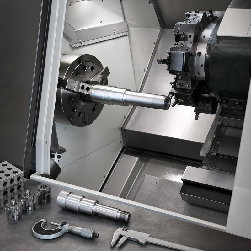
CNC Turning Center Specifications: Axes, Capacity, Tooling, Accuracy, and Buyer Notes

Quick answer: CNC turning center specifications describe what size, shape, material, accuracy, and features a lathe can produce. Important specs include chuck size, bar capacity, maximum turning diameter, turning length, spindle speed, turret tooling, live tooling, axes, and tolerance capability.

CNC Turning Center Specifications

A turning center is selected based on the part, not only on machine size. Shaft length, diameter, bore depth, thread type, groove position, live-milled features, material, and batch quantity all influence the best machine choice.

Key Points for Buyers and Engineers

Topic What to know Practical impact
Chuck size Workholding capacity for blanks Affects maximum part size.
Bar capacity Maximum bar diameter through spindle Important for production turned parts.
Turning length Maximum practical part length Controls shaft and sleeve feasibility.
Live tooling Milling/drilling tools on lathe Useful for cross holes, flats, and slots.
Axes X/Z plus C/Y or sub-spindle options Reduces secondary operations for complex parts.

How This Affects CNC Machined Parts

Turning centers are used for shafts, bushings, pins, sleeves, spacers, threaded parts, and round precision components. Review MTSPi’s CNC turning service for process fit.

Design and Purchasing Checklist

  • Provide maximum diameter and overall length.
  • Identify cross holes, flats, slots, and off-center features.
  • Confirm material, heat treatment, and finish.
  • Mark thread standards and inspection requirements.
  • Ask whether live tooling or secondary milling is needed.

Related MTSPi Resources

FAQ

What is a CNC turning center?

It is a CNC lathe that machines rotating workpieces and may include a turret, live tooling, sub-spindle, or additional axes.

What parts are made on turning centers?

Shafts, pins, bushings, sleeves, spacers, threaded fittings, and many round components.

What is live tooling?

Live tooling allows milling, drilling, or tapping operations on a turning center without moving the part to a separate mill.

Need help with CNC turning center part review?

Send drawings, material, quantity, finish, tolerance notes, and application requirements. MTSPi can review manufacturability before quoting.

Contact MTSPi for engineering and quote support

Practical Buyer Notes

Turning center specification pages should explain how machine specs affect real parts. Chuck size, bar capacity, turning length, spindle bore, turret stations, live tooling, and sub-spindle options all change what can be made efficiently.

Buyers usually do not need every machine parameter. They need to know whether their part diameter, length, material, thread, bore, cross holes, and tolerance fit the supplier’s turning capability.

How to Evaluate This Topic on a Real Drawing

Decision point Recommended approach Why it matters
Part diameter Check chuck size and turning diameter Determines whether the blank can be held and machined
Bar-fed production Check bar capacity Important for repeated small turned parts
Cross features Look for live tooling or secondary milling Reduces extra setups
Long shafts Review length, support, and runout control Prevents deflection and poor concentricity

Common Mistakes to Avoid

  • Selecting a turning supplier based only on maximum diameter.
  • Ignoring cross holes, flats, slots, and off-center features.
  • Forgetting to define thread standards and gauges.
  • Not discussing runout, concentricity, or surface finish for rotating parts.

Recommended MTSPi Review Workflow

MTSPi should review turned parts by diameter, length, material, features, tolerance, and quantity. This determines whether standard turning, Swiss-type machining, mill-turn, or secondary milling is best.

  1. Confirm the part function, operating environment, and assembly risk.
  2. Review material, process, tolerance, surface finish, and inspection requirements together.
  3. Separate critical features from general dimensions so cost is not wasted on non-functional details.
  4. Use related resources such as CNC materials, surface treatment, and quality assurance to complete the specification.
  5. Send the final drawing package to MTSPi for quote review before production.

What to Send for a Faster Quote

Send the drawing with diameter, length, bore, thread, groove, surface finish, material, quantity, and any runout or concentricity requirements.

  • 3D CAD file and 2D drawing with revision number.
  • Material grade or acceptable alternatives.
  • Quantity, delivery target, and whether samples are required first.
  • Critical dimensions, thread callouts, finish notes, and inspection requirements.
  • Application notes when the part is used in heat, moisture, wear, vibration, or visible assemblies.

Deeper Engineering Notes

For CNC turning center specifications, the strongest page is not just a definition. It should help a buyer decide what information belongs on the drawing, what questions to ask a supplier, and which details affect cost, quality, and delivery. In real RFQ work, the important details are usually bar capacity, chuck size, turning length, live tooling, sub-spindle use, runout, and concentricity. These details decide whether the supplier can quote confidently or has to return with repeated questions.

The common risk is ignoring cross holes, flats, slots, and secondary features when choosing a turning supplier. That risk can make the content look complete on the surface but weak in a real manufacturing situation. A stronger specification connects the topic to material behavior, machine access, tolerance control, finishing, and inspection before the order is released.

Example Specification Review

Review area Question to answer Good specification practice
Function What does this feature or part need to do? Describe the load, fit, motion, appearance, sealing, or assembly requirement.
Material Is the selected material suitable for the environment? Confirm strength, heat, corrosion, wear, chemical exposure, and cosmetic needs.
Geometry Can the feature be reached by standard tools? Review depth, corner radius, wall thickness, tool clearance, and setup direction.
Tolerance Which dimensions are truly critical? Use tight tolerances only where function requires them and keep general dimensions practical.
Verification How will acceptance be checked? Define gauges, CMM checks, roughness measurement, thread inspection, or visual standards when needed.

How This Page Should Support Ranking

This topic can attract both beginner searches and buyer searches. The beginner wants a clear answer; the buyer wants enough detail to make a manufacturing decision. A page has a better chance to rank when it answers the simple question first, then adds examples, process limits, design notes, comparison tables, and practical next steps.

That is also why internal links should be helpful rather than forced. A reader should naturally move from this page to a process page, material page, surface finish page, inspection page, or quote page only when that next step solves a real question.

Conclusion

Turning center specifications matter because they determine whether a part can be made efficiently in one setup. Clear drawings help the supplier choose the right turning route.

Categories
Blog CNC Materials Design, Cost & Sourcing

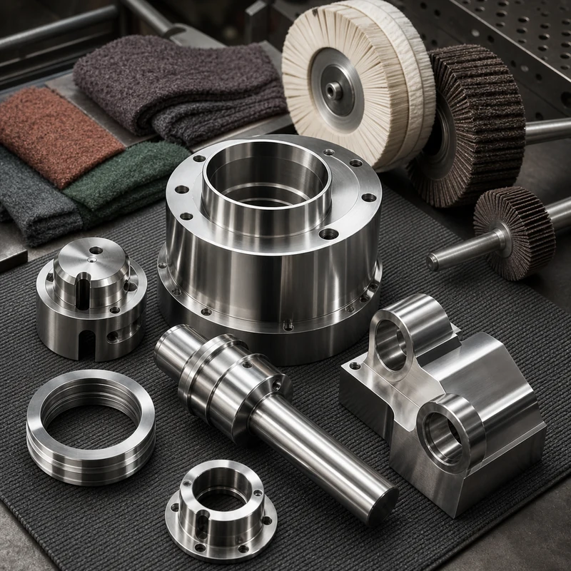
How to Polish Stainless Steel CNC Parts: Finishing Methods and Design Notes

Stainless steel CNC parts are polished to remove tool marks, improve appearance, reduce roughness, prepare for cleaning, or support corrosion-resistant service. The best method depends on the stainless grade, starting surface, part geometry, cosmetic expectations, and whether the finish is decorative, functional, or both.

Polishing should be planned before production rather than treated as a last-minute cosmetic step. MTSPi can combine stainless steel CNC machining, surface finish planning, and quality checks so machined features and finished surfaces match the drawing intent.

Why Polish Stainless Steel Parts?

  • Remove visible cutter marks, burr traces, scratches, or handling marks.
  • Create a brushed, satin, bright, or mirror-like appearance.
  • Reduce surface roughness where cleaning, sealing, or flow behavior matters.
  • Improve corrosion performance when polishing is paired with proper cleaning or passivation.
  • Prepare selected surfaces for assembly, inspection, or customer-facing use.

Common Polishing Methods

Method Typical Result Best Use
Deburring and edge blending Safer edges and cleaner transitions General machined parts before cosmetic finishing
Abrasive grinding Removes deeper tool marks and uneven areas Pre-polish correction or weld/stock cleanup
Brushing Uniform directional satin texture Panels, covers, brackets, visible housings
Buffing Bright reflective surface Decorative components and customer-facing hardware
Mirror polishing Very high reflectivity after staged abrasives Optical, medical, food, and premium cosmetic surfaces
Electropolishing Electrochemical smoothing and cleaning Complex stainless parts, hygienic surfaces, and corrosion-sensitive applications

A Practical Stainless Steel Polishing Workflow

1. Define the target finish

The finish should be described with a surface roughness value, visual standard, grain direction, sample photo, or approved reference part. Terms like “nice polish” or “shiny” are too vague for repeat production.

2. Machine with finishing allowance in mind

Polishing removes material. If a critical diameter, sealing surface, or flatness callout will be polished, the machining plan may need allowance and inspection after finishing. Tight features should not be polished aggressively unless the drawing accounts for it.

3. Remove defects gradually

Deep scratches, heavy cutter marks, and sharp edges should be reduced with controlled abrasives before fine polishing. Jumping directly to a fine compound can leave hidden waves, dull patches, or inconsistent reflections.

4. Clean and protect the part

After polishing, stainless steel parts should be cleaned to remove abrasive residue, compounds, oils, and loose particles. Depending on the application, passivation or electropolishing may be specified to improve surface cleanliness and corrosion behavior.

Stainless Steel Grades and Finish Behavior

Grade Family Polishing Notes Typical CNC Use
304 stainless steel Polishes well and is widely used for general corrosion resistance Housings, brackets, food equipment, covers
316 stainless steel Good corrosion resistance and common in harsher environments Medical, marine, chemical, and hygienic components
17-4 PH stainless steel Can be heat treated; finish planning should account for hardness condition High-strength shafts, fixtures, aerospace and industrial parts
303 stainless steel Machines well, but corrosion and finishing expectations should be checked Turned parts, fittings, fasteners, bushings

Design Notes Before Specifying a Polish

  • Avoid deep narrow pockets if the inside surfaces must be cosmetically polished.
  • Mark which faces are cosmetic and which are non-visible functional surfaces.
  • Specify grain direction for brushed finishes on panels or covers.
  • Confirm whether threaded holes, sharp edges, datums, and bores must be protected during finishing.
  • Define inspection after finishing when surface removal could affect tolerances.

Polishing vs Passivation vs Electropolishing

Mechanical polishing changes texture and appearance by physically smoothing the surface. Passivation chemically removes free iron and supports corrosion resistance. Electropolishing removes a thin surface layer electrochemically, which can smooth micro-peaks and improve cleanliness on suitable stainless parts. These processes can be combined, but they are not interchangeable.

Process Main Purpose Changes Dimensions?
Mechanical polishing Appearance and roughness control Yes, depending on abrasive stage and pressure
Passivation Surface chemistry and corrosion support Minimal dimensional change
Electropolishing Micro-smoothing, cleaning, and corrosion support Small controlled material removal

How MTSPi Supports Stainless Finishing

For stainless components, MTSPi reviews machining, polishing access, tolerance risk, edge requirements, cleaning, and inspection before production. Send your 3D model, drawing, stainless grade, target finish, cosmetic faces, and quantity through our RFQ channel.

Related MTSPi Resources

FAQ

Can all stainless steel CNC parts be mirror polished?

Not always. Mirror polishing depends on grade, geometry, access, starting surface, tolerance limits, and cost. Some internal features are impractical to polish uniformly.

Does polishing improve corrosion resistance?

A smoother and cleaner surface can help, but corrosion performance also depends on stainless grade, contamination control, passivation, environment, and maintenance.

Categories
Blog CNC Materials Quality & Tolerances

What Is Mechanical Testing? Methods, Data, and CNC Part Applications

Mechanical testing evaluates how a material, coupon, or finished component behaves under controlled load, impact, temperature, wear, or repeated stress. For CNC machined parts, it helps engineering teams confirm whether a selected metal or plastic can meet strength, durability, and safety requirements in real service.

Mechanical testing is different from routine dimensional inspection. A caliper, micrometer, or CMM checks size and geometry; a mechanical test checks performance. MTSPi supports precision projects with quality assurance, material review, dimensional inspection, and documentation planning for custom machined parts.

What Mechanical Testing Measures

Property What It Shows Why It Matters for CNC Parts
Tensile strength Resistance to pulling force before fracture Useful for brackets, shafts, housings, fastened joints, and load-bearing parts
Yield strength Stress level where permanent deformation begins Helps prevent bent, distorted, or misaligned components
Hardness Resistance to indentation and local wear Important for sliding surfaces, tooling interfaces, pins, bushings, and wear parts
Impact toughness Ability to absorb sudden energy Relevant for parts exposed to shock, handling damage, or low-temperature service
Fatigue behavior Resistance to repeated cyclic loading Critical for moving assemblies, robotics, aerospace hardware, and vibration-prone parts

Common Mechanical Test Methods

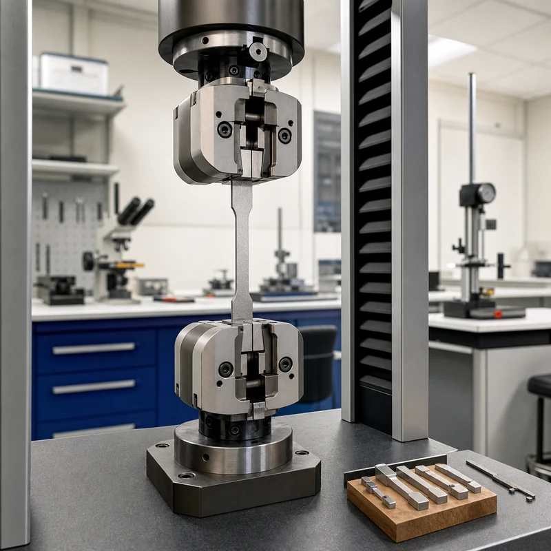
Tensile testing

A prepared sample is pulled until it yields and eventually breaks. The resulting stress-strain curve can show elastic behavior, yield point, tensile strength, elongation, and fracture response. For production parts, tensile data is often supplied through material certificates rather than testing every machined component.

Compression and bending tests

Compression testing checks how a material behaves under squeezing load, while bend testing evaluates ductility and resistance to cracking. These methods are useful when parts see clamp loads, forming forces, press fits, or structural bending in service.

Hardness testing

Rockwell, Brinell, Vickers, and microhardness methods estimate resistance to indentation. Hardness checks are common after heat treatment, surface hardening, or material substitution, especially for steels, tool steels, stainless steels, and wear-focused components.

Impact and fracture tests

Impact testing measures how much energy a material absorbs during a fast strike. Fracture-related testing is useful when brittle failure, low-temperature exposure, or safety-critical loading must be understood before a design is released.

Fatigue testing

Fatigue testing repeats load cycles until cracks initiate or failure occurs. It is important for parts that rotate, vibrate, flex, or see repeated assembly loads. Fatigue risk is affected by material, surface finish, corners, threads, inclusions, and machining marks.

Mechanical Testing vs Dimensional Inspection

Check Type Primary Question Typical Tools
Dimensional inspection Does the part match the drawing size and geometry? CMM, micrometers, calipers, height gauges, pins, optical measurement
Mechanical testing Will the material or part perform under load or use conditions? Tensile frames, hardness testers, impact testers, fatigue rigs, environmental chambers
Surface and finish checks Is the surface suitable for wear, sealing, adhesion, or appearance? Profilometers, visual standards, coating-thickness gauges

When Buyers Should Request Mechanical Testing

  • The part is load-bearing, safety-related, or used in aerospace, medical, robotics, energy, or industrial machinery.
  • The drawing requires a material standard, heat treatment condition, hardness range, or certified test report.
  • A new material grade is being substituted for cost, supply, weight, or corrosion reasons.
  • The part has thin sections, stress concentrations, threads, press fits, or surfaces exposed to repeated load.
  • A prototype failed during use and the team needs to separate material issues from design or machining issues.

How Machining Can Affect Test Results

CNC machining can influence part performance through surface finish, residual stress, sharp internal corners, burrs, tool marks, heat input, and grain direction in stock material. A strong material can still fail early if the design creates high local stress or if finishing leaves a poor surface at a critical location.

  • Use generous internal radii where loads change direction.
  • Avoid unnecessary sharp notches around highly stressed features.
  • Specify surface roughness where fatigue, sealing, or sliding behavior matters.
  • Confirm heat treatment and hardness requirements before machining begins.
  • Keep material certificates tied to the correct lot and drawing revision.

Material Families and Testing Priorities

Material Family Common Tests Design Note
Aluminum alloys Tensile, hardness, fatigue, corrosion checks Useful for lightweight parts, but thread and fatigue design need care
Stainless steel Tensile, hardness, corrosion, impact where needed Good corrosion resistance, with grade-specific machinability and finishing behavior
Titanium Tensile, fatigue, fracture, hardness Strong lightweight option where heat control and surface condition are important
Engineering plastics Tensile, flexural, impact, creep, temperature exposure Performance depends strongly on temperature, moisture, and load duration

How MTSPi Uses Test Requirements

When a drawing includes mechanical testing or certification requirements, MTSPi reviews them during quoting so material choice, machining sequence, finishing, and inspection records line up with the final use. Share your CAD model, 2D drawing, material standard, required report type, and quantity through the contact page.

Related MTSPi Resources

FAQ

Is mechanical testing required for every CNC part?

No. Many parts only need dimensional inspection. Mechanical testing is most useful when material performance, certification, safety, or high-load service matters.

Can finished CNC parts be mechanically tested?

Sometimes. Many tests use standardized coupons, but finished parts can be tested in fixtures when the goal is to validate real assembly behavior.

Request A Quote

We'll Send You Back with Price Immediately!

DEC 1-31

XMAS SPECEIL

Up to

40% off

What Is Mechanical Testing? Methods, Data, and CNC Part Applications

We'll Send You Back with Price Immediately!